OH500调试说明书b
KOBO EBD500 说明书
KBD500 是 KOBO 公司生产的在线电化学分析仪之一,为高智能化在线连续监测仪。可以
配极谱式电极,自动实现从 ppb 级到 ppm 级的宽范围测量,是检测锅炉给水、凝结水、环保 污水等行业的液体中氧含量测量的专用仪器。 分析仪主要特点: 1、操作方便:
界面美观:采用高分辨率的液晶显示模块,所有的数据、状态和操作提示都是英文显示, 完全没有厂家自己定义的符号或代码。
开孔尺寸:138*138mm 16、重量:分析仪:0.8Kg ; 17、工作条件:环境温度:0~60℃ 相对湿度:<85%; 18、进出水连接管道:硬管或软管,外径有 Ø 8、Ø 10、Ø 12 三种规格。
2
第三章 电极使用
3.1 电极工作原理
本表采用极谱式电极,阳电极为 Ag/AgCl、阴电极为铂金(Pt)组成,两者之间充满特 殊成份的是电解液。由硅橡胶渗透膜包裹于电极四周。测量时,电极间加上 675mV 的极化电 压,氧渗透过隔膜在阴极消耗,同时等量的氧在阳极产生,这个动态过程进行到两边的氧分压 相同时达到平衡.此时两电极间的电流与氧分压成正比,分析仪检测到此电流,再经过一系列 变换,得到氧浓度和氧含量.同时,NTC(负温度系数热敏电阻)检测被测量液的温度,分析仪采 样后进行温度补偿,将氧浓度或氧含量折算成 25℃时的值。
左边翻。参照 5.3 节仪器的接线,线接好后,应让线留有一定的余量(便于下次打开机壳时 线不被拉断),再拧紧 PG13.5 的防水圈。
2、取线:先拧松 PG13.5 的防水圈,再把线往里边塞(若安装时线在机壳里留有一定的 余量就不用进行这一步)。用螺丝刀拧松上盖的四颗螺钉,把上盖左边往上提,再从右往左 边翻。
第四章 安装与使用步骤
KBD500 在线溶解氧仪由分析仪、氧电极、测量池和连接分析仪与电极的电缆线四部分 组成。
HY500配料控制器使用说明书调试手册u
调试手册一、简介HY500配料控制器秉承更好更高的设计原则,采用大规模集成电路及高可靠器件,全数字化设计,非常适合建筑行业单配料机的自动生产控制。
具有操作简单方便、质量稳定可靠、控制精度高、价格合理等特点。
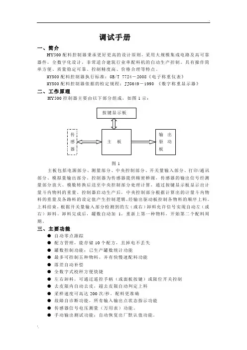
HY500配料控制器执行标准:GB/T 7724-2008《电子称重仪表》HY500配料控制器依据的检定规程:JJG649-1990 《数字称重显示器》二、工作原理HY500控制器主要由以下部分组成,如图1示:图1主板包括电源部分、测量部分、中央控制部分、开关量输入部分、打印/通讯部分、模拟量输出部分。
控制器为传感器提供精密桥源,传感器的输出信号经测量部分放大、模数转换后送至中央控制部分处理计算,通过按键显示板显示出计量斗内物料的重量。
控制器启动生产后,中央控制部分根据计算出的计量斗内物料的重量及各路料的设定值产生控制逻辑,经输出驱动板控制各物料的顺序上料。
上料结束,根据开关量输入部分检测到的左(或右)卸料允许信号实现自动左(或右)卸料。
卸料完成后,罐数自动加1,重新上第一种物料,开始第二个配料周期。
三、主要功能●自动零点跟踪●配方管理,能存储10个配方,且掉电不丢失●罐数控制功能;已生产罐数统计功能●最多可控制五种物料,并有快慢速配料功能●落差自动补偿●全数字式校秤方便快捷●左右卸料,可通过遥控手柄(或面板按键)或限位开关控制●去皮限内自动去皮,超去皮限自动判定上料●采样速度可高达200次/秒。
配料更准确●故障自诊断功能,所有输入输出点状态指示功能●传感器信号电压测量(万用表)功能。
●手动输出测试功能;自动恢复出厂默认值功能。
●通讯功能:标准的RS232或R485输出接口●打印功能,可带标准打印机或微型打印机●模拟输出接口,电流输出范围:4~20mA四、技术参数1、电源:交流220V±10%15%;50Hz±2%2、工作环境温度:0~40℃3、工作环境湿度:≤85%RH,无凝露4、桥源:5V±5%,最大负载能力200mA5、模拟量输入范围:0~18mV6、开关量输出触点容量:≤5A7、开关量输出触点电压:≤交流250V或直流24V8、最大显示:80009、控制器机壳外形尺寸:192mm×96mm×150mm(宽×高×深)10、电气控制柜开孔尺寸: 186+1mm×92+1mm(宽×高)五、前面板说明外观如图2示图2 前面板外观图(一)显示部分说明:1、配方号窗口待机态和运行态显示选用的配方号。
IHH500 Analog Output Guide
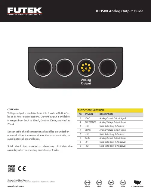
Sensor cable shield connections should be grounded on one end, either the sensor side or the instrument side, to avoid potential ground loops.Shield should be connected to cable clamp of binder cable assembly when connecting on instrument side.Sensor Solution SourceLoad · Torque · Pressure · Multi-Axis · Calibration · Instruments · Software 3+R1Solid State Relay 1 (Positive) 4VDAC Analog Voltage Output Signal 5+R2Solid State Relay 2 (Positive) 6GND Analog Current Output Return 7–R1Solid State Relay 1 (Negative) 8–R2Solid State Relay 2 (Negative)IHH500 Analog Output Guide2VOLTAGE OUTPUT1. From the main measurement screen press MENU to enter the mainmenu.2. Press ▼ to highlight OUTPUT CONFIG, and then press ENTER.3. Press ▼ to highlight VOLTAGE CONFIG, and then press ENTER.4. Select BI-POLAR or UNI-POLAR using the ◀ or ▶ arrow keys, and thenpress ENTER.a. Uni-Polar: Uni-Polar will set the voltage range to 0 VDC to +5VDC and shift the zero to 2.5VDC. This will result in a range of2.5 VDC to 5 VDC for positive outputs, and a range of 2.5 VDCto 0 VDC for negative outputs from the load cell.Ex. Compression can range from 2.5 VDC to 5 VDC, and Tensioncan range from 2.5 VDC to 0 VDCb. Bi-Polar: Bi-Polar will set the voltage range from -5 VDC to +5VDC with the zero load state at 0 VDC.Ex. Compression can range from 0 VDC to +5 VDC, and Tensioncan range from 0 VDC to -5 VDC5. The system will prompt: “WOULD YOU LIKE TO SAVE AS DEFAULT?”Press ENTER to save as default or BACK not to save as default.6. Press BACK to navigate back into the main menu.7. Press ▼ to highlight INTERFACES, and then press ENTER.8. Press ▼ to highlight VOLTAGE OUTPUT, and then press ENTER.9. Select ENABLE or DISABLE using the ◀ or ▶ arrow keys, and thenpress ENTER.10. The system will prompt: “WOULD YOU LIKE TO SAVE AS DEFAULT?”Press ENTER to save as default or BACK not to save as default.a. NOTE: If voltage output is ENABLED there will be a checkmarkon the right hand side ofthe VOLTAGE OUTPUT option.11. Press BACK to go back to the main menu.12. Press BACK again to exit the main menu and go back to the mainmeasurement display.CURRENT OUTPUT1. From the main measurement screen press MENU to enter the mainmenu.2. Press ▼ to highlight OUTPUT CONFIG, and then press ENTER.3. Press ▼ to highlight CURENT VALUE, and then press ENTER.4. Select the appropriate value using the ◀ or ▶ arrow keys, and thenpress ENTER.i. NOTE: The values range from the following options: 5-25 mA,0-20 mA, and 4-20 mA5. The system will prompt: “WOULD YOU LIKE TO SAVE AS DEFAULT?”Press ENTER to save as default or BACK not to save as default.6. Press ▼ to highlight CURRENT CONFIG, and then press ENTER.7. Choose UNI-DIRECTION or BI-DIRECTION using the ◀ or ▶ arrowkeys, and then press ENTER.a. Uni-Direction: Selecting Uni-Direction will result in the chosencurrent range to output for the load cell’s positive output only.b. Bi-Direction: Selecting the Bi-Direction option will result inshifting the zero of the selected current range to the middle ofthe range selected. This will result in the positive output fromthe load cell starting from the middle of the current range tothe highest value of the current range, and from the middle ofthe current range to the lowest value of the range for negativeoutputs from the load cell.Ex. If the range selected is 4-20 mA, the zero would shift to12mA and the positive output from the load cell will go from 12mA to 20 mA, while the negative output from the load cell willgo from 12mA to 0mA.8. The system will prompt: “WOULD YOU LIKE TO SAVE AS DEFAULT?”Press ENTER to save as default or BACK not to save as default.9. Press BACK to navigate back into the main menu.10. Press ▼ to highlight INTERFACES, and then press ENTER.11. Press ▼ to highlight CURRENT OUTPUT, and then press ENTER.12. Select ENABLE or DISABLE using the ◀ or ▶ arrow keys, and thenpress ENTER.13. The system will prompt: “WOULD YOU LIKE TO SAVE AS DEFAULT?”Press ENTER to save as default or BACK not to save as default.a. NOTE: If current output is enabled, there will be a checkmark onthe right hand side of the CURRENT OUTPUT option.14. Press BACK to go back to the main menu.15. Press BACK again to exit the main menu and go back to the mainmeasurement display.Drawing Number: SP1188-ACopyright © 2020. All rights reserved. FUTEK reserves the right to modify its design and specifications without notice. Please visit /termsandconditions for complete terms and conditions.FUTEK® Advanced Sensor Technology, Inc.10 Thomas, Irvine, CA 92618 USATel: (949) 465-0900Fax: (949) 465-0905。
OH-CONB763调试指导

FPA+, FPA-, 变频器侧为DB15插件 变频器侧为DB9插件 FPB+, FPB-, CM FPA, FPB, CM 变频器侧需要一根根 变频器侧需要一根根 接在Phoenix端子上 接在Phoenix端子上
FRNxxxLM1S-4C
PR
1,PR卡接口形式更改
2,主板取消未使用的端子
3,国产与进口的软件保持同步更新
F03 F04 富士变 频器 C32 L31 L32 F9 F11
1.0m/s 168 r/min 168 r/min 57.14% 105 m/min 66% 994mm/s 96 rpm
1.5m/s 168 r/min 168 r/min 85.71% 105 m/min 99% 1499 rpm 144 rpm
1.75m/s 168 r/min 168 r/min 100% 105 m/min 115% 1748mm/s 168 rpm
MCBC
公式 F03=主机额定转速值 F04=主机额定转速值 C32=(合同速度值/F03 对应的额定速度 值)*100% L31=F03 对应的主机的额定速度值 L32=C32*115% F8=F10 对应的速度值 F10=合同速度值对应的主机转速
L03 Old:0 New:
拆除MCBC短接线 ERO运行 是否出现oc2/ ere等故障 否 ERO正常运行 磁极整定成功
“3”表示主 机磁极的 定位方式
动力线、编码器线正确连接 接地线连接良好
是
磁极自整定失败
模拟量整定 (调整变频器参数C31)
检查编码器线、 主机相序
断开控制柜电源
使EN 有效
输入代码“3”并按Shift+Enter 保存参数值
OH5000电梯1.75米调试培训印刷版

0 1 1 1 1 0 1 0 0 正常下行(FR-D)
0 1 1 0 1 1 0 0 0 正常上行(FR-U)
01011 0 1 0 1
检修下行
01001 1 0 0 1
检修上行
0 0 0 0 0 0 0 0 0/1 等待下次运行(WT)
BEING THE BEST AT WHAT WE DO
LSVF_W:DS信号
无齿轮电机的定位(硬件准备)
Ø 无齿轮电机在运行之前必须进行编码器定位, 定位前:
1. 曳引轮上的钢丝绳必须取下; 2. 短接接触器,并确认接触器吸合; 3. 短接抱闸继电器,手动曳引轮确认抱闸打开; 4. 可能会出现Brake fbk loss和Contact fbk loss故
障,应进入Alarm config中将这两个故障屏蔽, 如有其他报警则应该排除故障后进行定位; 5. 准备短接线,最好是空气开关,应能在定位过 程中随时将Enable和Start和+24V;
2003年春节调试培训
OH5000电梯(1.75m/s)调试
SIEI变频器应用培训
BEING THE BEST AT WHAT WE DO
LCBII用于1.75m/sOH5000电梯
Ø 对于OH5000电梯1.75m/s系统,LCBII采用LSVF_ W的控制方式,即速度采用V码输出,输入信号使 用DS码。 • 用服务器设置LSVF_W控制方式: M1-3-1-4 Drive: 17;
BEING THE BEST AT WHAT WE DO
驱动器及电机参数的设置/检查
Ø 上电后首先检查STA RTUP/Startup config/ Setup mode中的Driv e data和Motor data, 参照右表。
PM500 电压调节器安装,操作和维护手册说明书

Maintenance ManualA Regal BrandIntroductionThe PM500 is an encapsulated electronic voltage regulator intended for use with the Marathon PMG systemand most Marathon AC generators. The PM500 controls the output of a brushless AC generator by regulating the DC current input to the exciter field. The PM500 is designed as a three phase or single phasetrue RMS sensing regulator that is capable of accepting analog voltage adjustment input. The PM500 is UL Recognized and UL Certified for Canada – Component per UL File E222903. The PM500 bears the CE markfor the European Union.SpecificationsSensing Input175 - 600Vac, True RMS, 60/50Hz, 3 Phase/1 PhasePower Input 175 - 260Vac, 300Hz PMG, 60/50Hz ShuntPower Output, Continuous 85Vdc at 3.5Adc with 240Vac input powerPower Output, Forcing 170Vdc at 7Adc for 10 sec. with 240Vac input powerFuse 5 x 20mm S505-5A, Slow Blow TypeVoltage Regulation ± 0.25%, with 4% engine governingExcitation Resistance9 ohms, minimumOver Excitation Protection Excitation exceeds 190Vdc or 7Adc for more than 10 seconds Manual Voltage Adjustment Range ± 20% with 2000 ohm rheostat± 10% with 1000 ohm rheostatAnalog Voltage Input A1 & A2 ± 20% with 0-10Vdc or ± 5Vdc biasUnder Frequency Factory Setting 58Hz preset for 60Hz operation and 48Hz preset for 50Hz operation Voltage Build-up Voltage build up from input voltage ≥ 5Vac at 25Hz.Response Time<1 CycleWeight16.6 oz.Operating Temperature -40°C to +60°CStorage T emperature -40°C to +85°CPower Dissipation12 watts, maximumSize 5.9” L x 5.3” W x 2.2” HThermal Drift 0.05% / °C change in AVR ambient temperature Electromagnetic Compatibility TestsImmunityIEC61000-4-2 - Electrostatic DischargeIEC61000-4-3 - Radiated RFIEC61000-4-4 - Electrical Fast TransientIEC61000-4-5 - SurgeIEC61000-4-6 - Conducted RFIEC61000-4-11EmissionEN61204-3 - Conducted RFCISPR 22IEC61000-3-2 - Harmonic IECIEC61000-3-3 - Flicker IEC2InstallationMOUNTINGThe PM500 is mounted through a keyed hole in the generator conduit box and secured with a plastic mounting nut.The PM500 should be mounted directly to the conduit box panel with the rubber gasket positioned between the outside of the conduit box panel and the mounting nut.Protect front panel adjustment pots by installing clear or black plastic cover.Mounting nut torque is 26 – 43 lbf-in. Refer to the Figure 1 for dimensions.Wiring and ConnectionsEXCITER FIELD POWER CIRCUITThe exciter field resistance must be ≥ 9 ohms.If the exciter field resistance is less than 9 ohms andthe full load field current does not exceed 3.5 amps, add a resistor in series of sufficient wattage to increase the total resistance to 9 ohms.Connect the generator F+ (F1) field lead to the regu- lator F+ terminal. Connect the generator F- (F2) field lead to the regulator F- terminal. Refer to Figure 3 for typical connection points.POWER I NPUT C IRCUITThe PM500 is designed to be powered by a PMG and capacitor. A 7.5µƒ capacitor is connected in parallel between the PMG leads and the regulator power input terminals.The regulator power input terminals are labeled P1 and P2. Connect leads from P1 and P2 to the capacitor terminals.Connect regulator terminals P1 & P2 to generator leads that will provide 240Vac output. No capacitor is used with the PM500 in shunt mode.Refer to Figure 3 for typical connection points.Figure 23TO PREVENT PERSONAL INJURY OR EQUIPMENT DAMAGE, ONLY QUALIFIED PERSONNEL SHOULD INSTALL, OPERATE OR SERVICE THIS DEVICE.Figure 1Wiring and Connections (cont’d)Figure 3a – Three PhaseFigure 3b – Single PhaseSENSING CIRCUITSSensing input range is 175 - 600Vac. DIP switch SW1 and SW2 must be set appropriately. Refer to Figures 3a & 3b for typical connections.Single Phase SensingConnect PM500 terminal E1 to output lead L1 and E2 to output lead L2. PM500 terminal E3 is jumpered to E2. 3 Phase SensingConnect PM500 terminal E1 to output lead L1, E2 to output lead L2 and E3 to output lead L3.If used in a paralleling application, a paralleling CT will be required in the generator B phase. Paralleling CT must be sized to provide either a 1A or 5A signal when the generator is under full load.4Wiring and Connections (cont’d)DIP SWITCH PROGRAMMINGEight DIP switches located on the back of the regulator must be set appropriately for correct regulator operation and generator control. Refer to Figure 4.Switches 1 & 2 set the regulator sensing range.Switches 3 – 8 Configure multiple functions: 3 or Single Phase Sensing, Frequency, Over Excitation Protection, kW Range and Paralleling CT Range.SW1 : OFF SW2 : OFF Volts ≤ 280VacSW1 : OFF SW2 : ON Volts ≤ 480VacSW1 : ON SW2 : ON Volts ≤ 600VacOFF ONSW3 : 3 Phase Sensing 1 Phase SensingSW4 :60 Hz 50 HzSW5 :O/E Protect On O/E Protect OffSW8 :CT 1A CT 5ASW6 : OFF SW7 : OFF< 90kWSW6 : ON SW7 : OFF90 - 500kWSW6 : ON SW7 : ON> 500kW PROTECTION F UNCTIONSThe PM500 has built in protection functions for Over Excitation, Under Frequency and Over Voltage Protection.Over ExcitationThe Over Excitation function protects the PM500 and generator components in the event the excitation system demands excessive levels of voltage and/or current to maintain output.The Over Excitation function will trip when excitation output exceeds 190Vdc or 7Adc for more than 10 sec. with 220Vac input power.The Over Excitation O/E LED on the front panel will be illuminated when thePM500 when the OverExcitation system has tripped. Replace the fuse on theback panel if required and inspect the generator. ThePM500 will reset when power is cycledUnder FrequencyUnder Frequency protection allows the generatorvoltage to decrease when the output frequency dropsbelow the Roll-Off point. This reduces the load on theengine, allowing engine RPM to recover. This is normaloperation and no reset is required.5 Figure 4Operating AdjustmentsSix adjustable potentiometers are accessible on the front panel of the PM500. These are: VOLT, STAB, U/F, DIP, DROOP and TRIM.Figure 6VOLTAGE ADJUST (VOLT)Set PointOutput voltage may be adjusted via the VOLT poten- tiometer on the front panel of the regulator. The set point range is 175 - 600Vac.Remote Voltage AdjustA 2000 ohm, 2 watt rheostat may be connected to VR1 and VR2 - replacing the factory jumper, providing a ±10% voltage adjustment range. T erminals A1 & A2 may not be used when a rheostat is installed.Analog Voltage AdjustRegulator terminals A1 & A2 may be connected to the analog output of a gen-set controller. The allowable voltage input range is 0-10Vdc or ± 5Vdc will provide a 20% range. Jumper VR1 & VR2 when analog voltage adjustment terminals are used.TRIM ADJUST (TRIM)The analog bias range is adjusted via the TRIM potenti-ometer on the front panel. Set the TRIM potentiometer fully clockwise to provide a ± 20% adjustment range. DROOP ADJUST (DROOP)Requires a 1A or 5A CT in the B Phase.DIP switch SW8 must be set appropriately.In a paralleling system, the PM500 adjusts the genera- tor output voltage when the B phase current leads or lags the B phase voltage.The adjustment range may be preset via the DROOP potentiometer. The default setting is full counter clock-wise for minimum range. Maximum range is ±7% at 1.7 PF lagging to 0.7 PF leading.UNDER FREQUENCY ROLL-OFF ADJUST (U/F) The Roll-Off point is the frequency at which the gen- erator output voltage is allowed to decrease and is factory preset at 57Hz for 60Hz operation and at 47Hz for 50Hz operation.When the U/F LED on the front panel it lit, the PM500 is operating in Under Frequency mode.To change the roll-off point, first verify that the gen-set is operating at the intended speed and voltage.Fixed Engine RPMOn most new engines (Tier 4i and up), the engine speed is fixed at 1800RPM or 1500RPM.Adjust the roll-off point by block loading the genera-tor and observing the U/F LED on the front panel. To ensure the generator maintains voltage under a given block load, adjust U/F potentiometer until the U/F LED remains off during the block load test.Adjustable Engine RPMAdjust engine speed to the new roll-off point. Verify that the output voltage still matches the intended set-point voltage.Next, adjust the U/F potentiometer clockwise until the voltage starts to drop off, then slightly adjust the poten- tiometer counterclockwise until the voltage returns to rated voltage. Re-adjust engine speed to rated speed. U/F DIP ADJUST (DIP)When Under Frequency (U/F) protection is activated, the voltage dip follows a linear Volts / Hertz curve. The voltage dip ratio may be adjusted via the DIP potentiometer with an adjustable range of 3-10V/Hz. The default setting is full clockwise for 10V/Hz. STABILITY ADJUST (STAB)Stability is the ability of the generator to respond to load changes. Decreasing the stability setting allows the generator to respond faster to load changes. If the stability setting is too low, the generator voltage will tend to hunt under steady state conditions.Correct stability adjustment must be conducted while the generator is operating unloaded.Adjust the STAB potentiometer clockwise until the voltage becomes unstable, then slightly adjust coun- terclockwise (Approximately 1/5 turn) until the voltage becomes stable.6Warnings & CautionsIMPORTANT INFORMATIONPlease Read CarefullyThis document is not intended to provide operational instructions. Appropriate Marathon Electric instructions provided with the generator and precautions attached to the generator should be read carefully prior to installation, operations and/or maintenance of the equipment. Injury to personnel or generator failure may be caused by improper installation, maintenance or operation.The following and information is supplied to you for your protection and to provide you with many•Buyer shall be solely responsible for determining the adequacy of the product for any and all uses to which Buyer shall apply the product. The application by Buyer shall not be subject to any implied warranty of fitness for a particular purpose.•For safety, Buyer or User should provide protective guards over all shaft extensions and any moving apparatus mounted thereon. The User is responsible for checking all applicable safety codes in his area and providingsuitable guards. Failure to do so may result in bodily injury and/or damage to equipment.•Hot oil can cause severe burns. Use extreme care when removing lubrication plugs.•Disconnect power and lock out drive equipment before working on a generator.•Always keep hands and clothing away from moving parts.•The lifting eyes on the generator are not to be used to lift the entire generator set. Only the generator may be safely lifted by the lifting eyes. Do not use the conduit box for lifting or support of the generator.•Install and ground the generator per local and national codes.•Discharge all capacitors before servicing the generator.•Misapplication of a generator in a hazardous environment can cause fire or an explosion and result in serious injury.•Never attempt to measure the temperature rise of a generator by touch. Temperature rise must be measured by thermometer, resistance, imbedded detector or thermocouple.•Operation of a generator at higher than its nameplate ratings may result in fire, damage to equipment or serious injury to personnel.•Do not apply any force to the generator fan when rotating the generator rotor.•Generators should not be operated faster than their rated speed.•The following statement is only applicable to high voltage generators (above 5000 V). A grounding strap is supplied from the generator neutral to ground. This grounding strap not only bleeds off any voltage potential on the main statorafter the high potential test, but also bleeds off any static charge that can build-up on the main stator during shipmentand storage. THIS GROUND STRAP IS NOT A PERMANENT PART OF THE GENERATOR CONSTRUCTION. REMOVETHIS GROUND STRAP ONLY AFTER A PERMANENT GROUND IS INSTALLED ON THE GENERATOR MAIN STATOR(not supplied by Marathon Electric), OR THE GENERATOR FINAL INSTALLATION IS COMPLETE.•Mounting bolts should be routinely checked to ensure that the unit is firmly anchored for proper operation.•Consult qualified personnel with questions. All electrical repairs must be performed by trained and qualified personnel only.•For inverter applications, follow the inverter manufacturer’s installation guidelines.•Make sure the generator is properly secured and aligned before operation.•When installing the generator, insure that loose parts or tools do not fall inside the generator.•When connecting the generator, be sure to follow the correct wiring diagram for the desired voltage. Insure that the voltage regulator is connected per the wiring diagram.RESALE OF GOODSIn the event of the resale of any of the goods, in whatever form, Resellers/Buyers will include the following language in a conspicuous place and in a conspicuous manner in a written agreement covering such sale:The manufacturer makes no warranty or representations, express or implied, by operation of law or otherwise, as to the merchantability or fitness for a particular purpose of the goods sold hereunder. Buyer acknowledges that it alone has deter- mined that the goods purchased hereunder will suitably meet the requirements of their intended use. In no event will the manufacturer be liable for consequential, incidental or other damages. Even if the repair or replacement remedy shall be deemed to have failed of its essential purpose under Section 2-719 of the Uniform Commercial Code, the manufacturer shall have no liability to Buyer for consequential damages.Resellers/Buyers agree to also include this entire document including the cautions and warnings above in a conspicuous place and in a conspicuous manner in writing to instruct users on the safe usage of the product.This information should be read together with all other printed information supplied by Marathon Electric.For more information contact: Regal Beloit America, Inc., 100 E. Randolph St., Wausau, WI 54401Phone: 715-675-3311 or Fax: 715-675-80267A Regal Brand100 E. Randolph Street PO Box 8003Wausau, WI 54402-8003 U.S.A. PH: 715-675-3359 FAX: 715-675-8026 ©2019 Regal Beloit Corp GPN056 v1.2100/11-19/FSPrinted in the U.S.A.。
G013 GHJ-500转筒混合机标准操作规程ok
威海华新药业集团有限公司操作标准文件标题:GHJ-500转筒混合机标准操作规程总页—分页2-1 版号A/0-2013 文件编号SOP-SB-G013起草人日期原文件编号-审核人日期生效日期审核人日期颁发单位质量保证部批准人日期印数编号分发单位及数量生产副总经理、质量副总经理、工程部、生产部、质量保证部、软件室各1份,制造部2份。
目的:建立GHJ-500转筒混合机标准操作规程,使之操作规范化、标准化、程序化。
范围:适用于本公司GHJ-500转筒混合机的操作。
职责:工程部具有资格的技术人员负责制订;工程部经理、质量保证部经理负责审核;生产副总经理批准;车间设备操作工、设备管理员、维修人员执行。
内容:1编制依据1.1《GHJ-500转筒混合机使用说明书》。
1.2 结合设备安装、调试、验收过程;1.3《标准操作规程(SOP)编制与管理规程》(SMP-WJ008)。
2工作原理主要靠机械搅拌器、气流和待混液体的射流等,使待混物料受到搅动,以达到均匀合搅动引起部分液体流动,流动液体又推动其周围的液体,结果在溶器内形成循环液流,由此产生的液体之间的扩散称为主体对流扩散。
搅动引起的液体流动速度很高时,在高速液流与周围低速液流之间的界面上出现剪切作用,从而产生大量的局部性漩涡。
这些漩涡迅速向四周扩散,又把更多的液体卷进漩涡中来,在小范围内形成的紊乱对流扩散称为涡流扩散。
混合时要求所有参与混合的物料均匀分布。
混合的程度分为理想混合、随机混合和完全不相混三种状态。
各种物料在混合机械中的混合程度,取决于待混物料的比例、物理状态和特性,以及所用混合机械的类型和混合操作持续的时间等因素。
设备主要技术参数:搅拌桨转速转/分:24 混合槽翻转角度℃:360℃混合槽翻转速度r/min转/分9r/min3操作条件GHJ-500转筒混合机标准操作规程文件编号SOP-SB-G0133.1操作人员经GMP、生产指令、“SOP”培训,考试合格后持证上岗;3.2设备挂“已清洁”、“完好”状态标志表示设备可正常运行。
FDF-500使用说明(双工器的调试)
FDF-500多功能扫频仪说明书特性:外接电压:12V/1A 电池电压:7.2-8.4V 内部充电电流:270ma.恒流恒压。
8.4V截止工作电流:540ma(强背光800ma,适合强光下使用)3.5寸TFT彩色液晶显示屏,分辨率320*480。
有效波形显示面积:270*360频率范围:扫频模式0.1-500MHz 驻波模式2-500MHz 步进频率:0.1-150M:1HZ 150-275M:2.5KHZ 275-500M:5KHZ输出幅度:谐波:1MHZ 10DB 2MHZ 12DB 5MHZ 12DB 7MHZ 12DB 10MHZ 12DB 14MHZ 12DB 18MHZ 12DB 21M 12DB25M 14DB 29M 15DB 50M 15DB 75M 24DB100M 45DB 125M 30DB 137M以上均大于30DBAD8307对数检波器。
(扫频测试部分)AD8361检波器(驻波测试部分)2个活动频标。
概述FDF-500型扫频仪是一台集PLL,DDS,TFT显示,对数检波,ALC放大,32BIT控制器一体的多功能射频仪器。
工作范围0.1-500MHz内实现频幅特性,放大器增益,驻波检测等功能。
频率基准20MHZ/30PPM。
整机射频信号由DDS和PLL芯片产生,稳定性,一致性很高。
配套清单扫频仪主机1台12V/1A电源适配器1个N/N,M/M跳线1条0-40DB衰减器1个电池安装扫频仪自身不包含充电电池,所以用户需自行购买安装,推荐使用2个18650 /2200mAH锂离子电池(必须带保护板)串联使用。
安装时注意不要接错极性,电路板有二极管方向保护,小心烧坏电池。
操作使用-开机:电源开关为机器右侧上方拨动开关,朝上为开机,朝下为关机。
接线:信号输出和天线驻波测试公用一个端口,为仪器左侧下方的N/M母座。
在扫频模式信号输入为仪器左侧上方端口。
在驻波模式信号在机器内部检测,不需要使用输入口,此时输入口应该悬空。
虹润 OHR-A100 A104系列简易型单回路数字显示控制仪 使用说明书
仪表间最小间距W 38 34 38 38 15 32 15H 34 38 38 15 38 32 15仪表背面图(1)在表盘上安装仪表的方法按照不同仪表所需的开孔尺寸在盘面上开好对应尺寸的安装孔,将仪表嵌入到开好的安装孔中,然后在仪表两侧安装固定支架,拧紧螺丝使仪表固定在盘面上,再剥掉显示屏上的保护膜即可。
(如果在同一表盘上安装多台仪表,应参考上图中推荐的仪表间最小间距,以保证必要的散热及装卸空间)(2)从外壳中取出表芯的方法将仪表本体一侧的锁扣向外侧拨开,然后将仪表另一侧的面板与本体之间的卡扣向里顶下,抓住仪表的前面板向外拔,即可使表芯与表壳分离(见右图)。
在回装时,将表芯插入表壳后一定要推紧,并将锁扣锁紧,以保证安装可靠。
(3)安装说明★ 电缆的选择、仪表的安装和电连接必须符合VD0100“1000V以下电路安装的有关规定”或本地的有关规定★ 电连接必须由专业人员进行★ 负载电路应使用保险丝,以保护继电器触点在短路或电流超过继电器最大容量时自动切断电路★ 输入、输出和电源应单独布线,同时相互之间避免平行★ 在仪表的电源端子上不要连接任何其它负载★ 传感器和通讯线应使用屏蔽绞线(4)仪表标准配线说明★ 直流信号输入(过程输入)1、为了减小电气干扰,低压直流信号和传感器输入的连接线应远离强电走线。
如果做不到应采用屏蔽导线,并在一点接地2、在传感器与端子之间接入的任何装置,都有可能由于电阻或漏流而影响测量精度★ 热电偶或高温计输入应采用与热电偶对应的补偿导线作为延长线,应有屏蔽层★ RTD(铂电阻)输入三根导线的电阻值必须相等,每根导线的电阻不能超过15Ω面板卡扣锁扣三、仪表的显示面板和功能键显示测量值;在参数设定状态下, 显示参数符号显示输入分度号、报警值等,可根据要求自行选择显示;在参数设定状态下,显示设定参数值输出指示灯 运行指示灯第一报警指示灯 第二报警指示灯确认键:数字和参数修改后的确认翻页键:参数设置下翻键退出设置键:长按5秒可返回测量画面移位键:按一次数据向左移动一位复位键:长按5秒仪表复位减少键:用于减少数值增加键:用于增加数值PV显示窗SV显示窗确认键移位键减少键增加键报警指示灯OUT RUN AL1AL2显示窗PV显示窗SV显示窗指示灯OUT RUN AL1AL2按键四、选型表五、接线规格尺寸为A、B、C、D、E型接线图注:横竖式仪表后盖接线端子方向不一样,见示意图1图1123456789101112123456789101112A、DB、E二线制变送器接线方法PVIN{OUT {4PmA 5234343123123TCV mARTDYTZ 676767123456789101112Power/D Power/A +-{8910AL1AL2报 警8910AL135配电输出}L N1112RS485+-mAV+-+-+-p+-1112+-{配OHR-A100输出类型(负载电阻RL)无输出4~20mA(RL≤500Ω)1~5V(RL≥250KΩ)0~10mA(RL≤1KΩ)0~5V(RL≥250KΩ)0~20mA(RL≤500Ω)0~10V(RL≥4KΩ)RS485通讯接口(Modbus RTU)代码 X 0 1 2 3 4 5 D1电压范围AC/DC 100~240V(50/60Hz)DC 12~36V代码 A D 分度号(测量范围)热电偶B(400~1800℃)热电偶S(0~1600℃)热电偶K(0~1300℃)热电偶E(0~1000℃)热电偶T(-199.9~400.0℃)热电偶J(0~1200℃)热电偶R(0~1600℃)热电偶N(0~1300℃)F2(700~2000℃)热电偶Wre3-25(0~2300℃)热电偶Wre5-26(0~2300℃)热电阻Cu50(-50.0~150.0℃)热电阻Cu53(-50.0~150.0℃)宽*高*深160*80*110mm(横式)80*160*110mm(竖式)96*96*110mm(方式)96*48*110mm(横式)48*96*110mm(竖式)72*72*110mm(方式)48*48*110mm(方式)代码 A B C D E F H分度号(测量范围)热电阻Cu100(-50.0~150.0℃)热电阻Pt100(-199.9~650.0℃)热电阻BA1(-199.9~600.0℃)热电阻BA2(-199.9~600.0℃)线性电阻0~500Ω(-1999~9999)远传电阻0~350Ω (-1999~9999)远传电阻30~350Ω (-1999~9999)0~20mV (-1999~9999)0~40mV (-1999~9999)0~100mV (-1999~9999)内部保留内部保留0~20mA (-1999~9999)分度号(测量范围)0~10mA (-1999~9999)4~20mA (-1999~9999)0~5V (-1999~9999)1~5V (-1999~9999)内部保留0~10V (-1999~9999)0~10mA开方 (-1999~9999)4~20mA开方 (-1999~9999)0~5V开方 (-1999~9999)1~5V开方 (-1999~9999)全切换代号 13 14 15 16 17 18 19 20 21 22 23 24 25代号 00 01 02 03 04 05 06 07 08 09 10 11 12代号 26 27 28 29 30 31 32 33 34 35 55代码 X 12报警限数无输出1限报警2限报警简易型单回路数字显示控制仪,1℃分辨率OHR-A104简易型单回路数字显示控制仪备注:1、一路继电器(带有常开常闭触点) 触点容量:AC220V/3A、DC30V/5A (阻性负载) 二路继电器(仅一组常开触点) 触点容量:AC220V/3A、DC30V/5A (阻性负载)2、规格尺寸为H的仪表,继电器触点容量:AC125V/0.5A、DC24V/0.5A(阻性负载)代码 X P配电输出(输出电压)无输出配电输出如“P(24)”表示配电输出24V6.1 一级参数设置在工作状态下,按压 键PV显示LOC,SV显示参数字符:按增加、减少键来进行设置。
BG-Power500HC 电泳仪电源 快速说明书
1北京天竺空港工业区B 区裕华路28号7号楼 邮政编码:101300 BG-Power500HC电泳仪电源快速使用说明书1、 电源面板图示:“Advance”键:高级功能或保存程序“ESC”键:退回上一菜单“LOAD”键:调用已存程序上/下/左/右键:光标移动2、程序设定、保存及运行:开机主界面:“1.Manual 、2.Program”;点击“TAB”,选择模式1 或2 →“Enter for next”:①→进入“1.Manual”模式→“Enter for next”→(点击“上/下/左/右”键)选择“1.VOLT (恒压)、2.AMP (恒流)或3.WAIT (恒功率)”模式,数字键重新设定数值→“Enter for next”→设置运行时间(单位:小时)或伏/时(默认off )参数→点击“ ”键运行上述程序。
②→进入“2.Program”模式,→“Enter for next”→选择“1.CREAT (创建)、2.EDIT (编辑)、3.RUN (运行)或4.VIEW (预览)”模式,(以1.CREAT 为例)→“Enter for next”→设定电压、电流、功率、运行时间及伏/时等参数值(方法同①)→“Enter for next”→(Enter for add s* )程序如果包括多个步骤(Step),点击“Enter”重复上述设定,添加其余步骤,最多可设定9 个步骤// (Advance for save )程序设定完成,点击“Advance”将程序保存到指定的程序(Method :1,2…9)。
③点击“LOAD”键,直接预览、调用已存程序。
3、使用须知及个性化设计:①单步骤(one-step )电泳,可选择“1.Manual”模式设定程序; 多步骤电泳,选择“2.Program”模式或调用(LOAD )已存程序时,需预览(VIEW )程序确定无误后再启动运行。
②定时和三恒(恒压、恒流、恒功率)设定功能:时控范围1 分钟(00:01)~ 99 小时59 分钟(99:59);电压范围:10v~500v ,电流范围:0.01A~3.00A ;功率范围:5w~500w 。
- 1、下载文档前请自行甄别文档内容的完整性,平台不提供额外的编辑、内容补充、找答案等附加服务。
- 2、"仅部分预览"的文档,不可在线预览部分如存在完整性等问题,可反馈申请退款(可完整预览的文档不适用该条件!)。
- 3、如文档侵犯您的权益,请联系客服反馈,我们会尽快为您处理(人工客服工作时间:9:00-18:30)。
第 八 部 分 调试说明
OH5000 产品手册 第 8 部分 页码:第1 / 34 页 日期:2002-10-30 版本:第 A 版 修改:第 1 次
调试说明
OH5000
1. OH5000控制系统概述 OH5000控制系统引用了OTIS的MCS(模块化控制系统)中的LCBII(逻辑控制
板)作为电梯控制系统的核心,充分吸收了OTIS技术,利用OTIS高可靠性的串行通讯系统,将电梯的各个部件紧密的连在一起。驱动部分则采用意大利高精度的矢量变频技术,使电梯的运行更加平稳舒适,同时其流畅简洁的外观也令人赏心悦目。 LCBII内部包括四个模块子系统:OCSS(操作控制子系统) MCSS(运行控制子系统) DCSS(门控制子系统) DBSS(驱动和制动子系统) 产品手册 第 8 部分 页码:第2 / 34 页 日期:2002-10-30 版本:第 A 版 修改:第 1 次
调试说明
OH5000
1.1 下图为OH5000电梯1.0m/s控制系统基本框图:
LCB-II OCSS 操作控制
DBSS 驱动控制 DCSS门机控制 MCSS 运动控制 C/C轿相串行线
C/H厅外显示串行线
G/H厅外按钮串行线
XRDS DOL VFBDS DCL DO2000
AvyL-M 变频器
1LS,2LS 端站减速开关 IPU,IPD 正常减速开关 5LS,6LS端站限位开关 DZ门区信号 INS,ERO检修开关 安全回路
测速(2048) 无齿轮电动机
对 重
轿厢 ANS防骚乱 LWO超载 LWX满载 25L 50L
LPB2 Logic Processing Board D/A
启动力矩 产品手册 第 8 部分 页码:第3 / 34 页 日期:2002-10-30 版本:第 A 版 修改:第 1 次
调试说明
OH5000
1.2 下图是OH5000电梯1.75m/s控制系统基本框图:
LCB-II OCSS 操作控制
DBSS 驱动控制 DCSS门机控制 MCSS 运动控制 C/C轿相串行线
C/H厅外显示串行线
G/H厅外按钮串行线
XRDS DOL VFBDS DCL DO2000
AvyL-M 变频器
5LS,6LS端站限位开关 INS,ERO检修开关 安全回路
测速(2048) 无齿轮电动机
对 重
轿厢 ANS防骚乱 LWO超载 LWX满载 25L 50L
LPB2 Logic Processing Board D/A
启动力矩
1LS,2LS 端站减速开关 ULZ、DLZ门区信号 NTSD
DGFC 产品手册 第 8 部分 页码:第4 / 34 页 日期:2002-10-30 版本:第 A 版 修改:第 1 次
调试说明
OH5000
2. 调试操作 2.1 检查控制柜 打开控制柜的门,检查是否有连接处松动和元件损坏,保管好随机资料,更换已损坏的部件,紧固控制柜中所有连接处。紧固时请特别注意电源线、动力线和制动电阻的连接。
2.2 接线检查 按接线图,检查PVT线、随行电缆的临时接线、限位开关的临时接线,检查每个设备的接地线是否可靠接地。 2.3 绝缘检查 脱开接地线和HL的连接,拔出LCBII上的所有插件,将所有的空气开关都置于“OFF”位置,用绝缘表测量地线和HL、电源线、电机动力线、抱闸线圈、门机、照明两端的绝缘电阻值,确保绝缘电阻值在规定值之内。重新接上地线和LCBII板上的插件。 2.4 抱闸清洗和调节 2.4.1 清洗抱闸 2.4.1.1 按上锁挂牌程序,将电梯控制柜断电。 2.4.1.2 由于轿厢的空载重量比对重轻,为确保人身和设备的安全,在拆抱闸前必须将电梯的对重完全压在缓冲器上。 2.4.1.3 松开抱闸弹簧两端的螺母和锁紧螺母,慢慢取出弹簧,此时要注意,如果缓冲器未被完全压缩,轿厢会移动。 2.4.1.4 拆开抱闸,清洁铁心和轴销,检查抱闸刹车皮是否干净且与抱闸臂紧固相连。 2.4.1.5 将刹车鼓上的灰尘和铁锈清除。 2.4.1.6 重新装配抱闸。 2.4.2 调节抱闸(制动臂) 2.4.2.1 如下图所时,制动臂的压缩弹簧A动作时的压缩量为5~8mm。 2.4.2.2 调整螺杆与制动器触头的间隙,使B≥1.0mm。 2.4.2.3 调整螺杆与弹簧锁紧螺栓,使制动臂上磨擦片(闸瓦)与曳引轮的间隙C,保证在制动器动作时C≤0.7mm。 产品手册 第 8 部分 页码:第5 / 34 页 日期:2002-10-30 版本:第 A 版 修改:第 1 次
调试说明
OH5000
2.4.2.4 调整制动器后,应保证两边的抱闸应同时打开,在打开时闸瓦不能触碰到曳引轮,关闭时应可靠制动。 2.4.2.5 调节好抱闸后,还应调整螺杆D与抱闸检测开关触头E的间隙,保证在制动器关闭时,抱闸检测开关动作(触头被压紧);制动器打开时,检测开关不动作(触头松开)。 2.5 检查井道 2.5.1 确认对重重量是否合适。 2.5.2 检查各层厅门是否安装完毕,并且已经关上。 2.5.3 确认限速器绳已经紧固,限速器开关已经连接。 2.5.4 确认导轨已上油。 2.6 检查输入电压 切断主电源空气开关和控制柜内的其它空气开关,检查三相输入电压是否在规定范围之内(±10%),检查端子排上的C16、C17两端的电压(照明电压)是否为220V±10%。 2.7 检查控制变压器输出电压 合上主电源空气开关,检查变压器的输出端电压是否和图纸相符。 产品手册 第 8 部分 页码:第6 / 34 页 日期:2002-10-30 版本:第 A 版 修改:第 1 次
调试说明
OH5000
2.8 检查LCBII的输入输出电压 切断电压,拔去LCBII板上的所有插件,然后合上所有的空气开关,用万用表测量LCBII的P9插件的3,4脚,检查电压是否为DC30V±10%,如果不符,请检查控制变压器和整流桥堆、电容、P9的连线,如果符合,切断主电源,将P9插件插上,上电检查P8插件的电压应符合下表:
P8 SIGNAL TYPE VOLTAGE MEASURE 1 2 3 4 5 6 HL1 not used 24 VAC 24 VAC 24 VDC GND Input input Input Output Output
P8 / 5--P8 / 6 : 24 VDC + / -10 % 如果所测的电压值和上表所列出的不同,请检查: 从控制变压器到桥堆、电容、插件P9的连线。 如果接线没问题,请更换LCBII电子板。 2.9 上电检查LCBII的状态 2.9.1 切断主电源开关,插上所有的插件。 2.9.2 检查LCBII电子板上的SW1(CHCS)和SW2(DDO)开关所处的位置。微动开关SW1和SW2具有如下功能: SW1(CHCS) --OFF:正常操作; --ON: 取消厅外召唤。 SW2(DDO) --OFF:正常操作; --ON: 取消门操作。 SW3 --TL: 呼梯至顶层。 SW3 --BL: 呼梯至底层。 2.9.3 确认控制柜内ERO开关处于检修位置。 2.9.4 确认所有的厅门和轿门已经正确关闭。 2.9.5 合上主电源开关。 产品手册 第 8 部分 页码:第7 / 34 页 日期:2002-10-30 版本:第 A 版 修改:第 1 次
调试说明
OH5000
2.9.6 观察LCBII电子板上的指示灯,检查输入信号是否正确:
指示灯 说 明 状 态 MP BC VLC GRP/J NOR/D… INS ES DW DFC DOC DOB DZ RSL
马达保护装置 抱闸电流检测 电压检测(5V) 群控或三相电源错缺相 正常操作 检修操作 紧急停止操作 厅门关闭信号 厅门轿门全部关闭信号 开门到位开关 开门按钮 轿厢在门区 远程串行通讯 不亮 不亮 亮 不亮 不亮 亮 不亮 亮 亮 不亮 不亮 亮(仅在门区) 闪烁
注:如果上电后,指示灯的状态和表中所列出的状态不一致,请检查相关的电路和参数(一般参数在电梯出厂时已设定好)。
2.10 变频器参数设置 2.10.1 OH5000控制系统变频器参数设定 下表为OH5000控制系统中变频器的参数表,其中1.0m/s系统以6kw主机、1.75m/s系统以9.5kw主机,载重1000kg,平衡系数45%为例。 2.10.2 该表中不包括变频器中变频器和主机的参数,自学习参数以及定位数据等,这些数据应该根据实际的变频器、主机进行设置,并通过自学习和定位得到相应的值。注意:STARTUP/Starup config /Enter setup mode Br /DRIVE DATA /Spd ref /fbk res应设置为0.03125rpm。