一种用同步回转电火花加工精密轴内孔的方法外文文献翻译、中英文翻译、外文翻译
数字机起重机提升转换外文文献翻译、中英文翻译、外文翻译
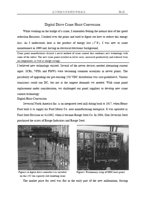
Digital Drive Crane Hoist ConversionWhile working on the bridge of a crane, I remember feeling the intense heat of the speed reduction Resistors. I looked over the prints and tried to figure out how to reduce this energy loss. As I understood, heat is the product of energy lost (R I 2). I was new to crane maintenance in 1990 and, having an electrical/electronic background,Crane panel manufacturers desired a novel method of crane control that combines new technology with some of the oldest. The new crane panel resulted in lower costs, increased productivity and reduced wear on components, as well as energy savings.I believed new technology existed. Several of the newer devices needed alternating current input. SCRs, VFDs and PMWs were becoming common acronyms in newer plants. The possibility of upgrading our pre-existing 250 VDC distribution was cost-prohibitive, Various transistors could run DC, but not at the ampere demands we needed. With crane panel replacement under consideration, we challenged our panel suppliers to develop new crane control technologyDigital Hoist ConversionSeverstal North America Inc. is an integrated steel mill dating back to 1917, when Henry Ford built it to supply his Ford Motor Co. auto manufacturing enterprise. It was operated as Ford Steel Division ur~ti11982, when it became Rouge Steel Co. In 2004, OAt Severstal Steel purchased the assets of Rouge Industries and Rouge Steel.Figure1.A digital drive controller was installed Figure2. Preliminary setup of DDC hoist panel on this 135-ton-capacity slab-handling craneThe market price for steel was flat in the early part of the new millennium, forcingdepartmental groups to look for cost-saving improvements. One improvement was the installation of a new type of digital electronic control panel in 2003. This panel represented the introduction of DC electronic crane control to Rouge Steel and the largest duplex crane hoist controller (dual 200-hp) of its type in North America.The original panels were built on a P&H 135-ton slab-handling crane having standard DC hoisting contactor controls. They were industrial and functional, designed to handle the loads of this crane in 1972. The loads are greater now with heavier slabs, runing the crane at maximum limits and higher production rates. This caused premature equipment failures and production down-time. With three aging cranes in this bay, maintenance costs were rising to new highs. Those involved in maintenance were finding that distributors and manufactures were downsizing or had gone out of business, making replacement parts costly or obsolete. The market drivers of today are forcing the change to newer technologiesFigure3. Digital panel installed on crane trolley deck Figure4.Prewired resistors reduced start-uptimeA novel design approach was asked of the crane panel manufactures. They replied with a proposed partnership and an effort to add some of the newest technology to the oldest methods of crane controls. The result was high-current transistor switching with a 250 VDC input. The design was well-thought-out and included integrating the original motors, limits, switches and wiring. Now speeds are controlled by sending the motors only enough current to safely lift and lower the load. The motors are soft stopped (reverse plugged) before the brakesclose. This saves wear on components, reduces costs and increases productivity. Without the need for reduction resistors, there is no energy wasted, maximizing the energy savings. The panel installation of the SY-4 crane was completed in 2003 and is still running. The results are smoother movements with little energy loss (heat).The new panels were designed for installation on the trolley deck, as opposed to the bridge deck.. This aids in troubleshooting and reduces excessive wiring mainly at the weak point of the cable powertrack.. This allowed the time and ability to perform all setup work during mini-downturns without disabling the original hoist. The original panel was left in place as a backup, as failures could not be predicted. To date, the fail-safe panel has not been required.The panels were pre-wired and pre-tested prior to crane installation, further reducing crane downtime. When the transfer day came, only the master switch, motors and limit leads needed to be rerouted to the new system. On-the-job tuning and monitoring were vital for the first couple of days. It was important to have crane operators involved for that “personal feel”and to obtain their buy-in to the project, to increase awareness and productivity. No-load and full-load current tests were run with great results.An aded benefit to this control is the electrical current savings. Without reductin resistors for speed points, and with the added benefit of power produced when regenerative lowering, this single crane installation saves more than $25000 in electricity annually. This can be a very important consideration if substation power is near critical usage levels. The demand this system imposes is much less than a similar contactor system. With energy costs on the rise, this is a concern for every project considered. Figure 5 indicates an example of electrical current savings potential by comparing contactor panel loads(top) to digital drive loads(bottom).How it works in the circuit is not unique. The insulated gate bipolar transistor(IGBT) takes the place of the contactors and acceleration resistors. As the master switch is selected for greater speed, the circuitry triggers the transistor at a frequency(pulse width modulated) that allows current to flow through the IGBT. The current circulates in the standard series armature and series field along with the series brake. The longer the input is turned on, thehigher the output average voltage (Figure 6). The higher the voltage, the higher the horsepower produced. This system can provide high torque with low currents(heat) as the result of motor regenerative properties. High speed with no load can also be accomplished. Much of this could not be achieved with the original panels.Figure5.Example of energy saved during lowering sequence.The difference is noticed when the IGBT is in its off cycle(Figure 7). In this instance, the motor acts as a generator, producing circulating currents through the flyback diode and maintaining self-induced motor currents. This effect reduces ripple and provides current that was not provided by the original power source. The reduction of current loads on system feeders and hardware further adds to the total savings package.The following items are important considerations when determining if this system will work with an application.IGBTs are the newest part of the design that makes this panel work with 250 volts DC. They combine the advantages of the bipolar transistor(high voltage and current) with the advantages of the metal oxide semiconductor field effect transistor(MOSFET)(low power consumtion and high switching). IGBTs are semiconductors that combine a high voltage and high current bipolar junction transistor(BJT) with a low-power and fast-switching MOSFET. Consequently, IGBTs provide faster speeds and better drive and output characteristics than power transistors and offer higher current capabilities than equivalent high-powered transistors.Figure6.Hoist current flow when the IGBT is onFigure7.Hoist continuing motor current flow when the IGBT is off.Heat sinking, including consideration of air temperature and air flow, is essential to the proper operation of any solid-state reply. It is necessary to rovide an effective means of removing heat from the IGBT. The importance of using a proper heat sink cannot be overstressed, since it directly affects the maximum usable load current and maximum allowable ambient temperature. Up to 90 percent of the problems with transistors are directly related to heat. Lack of attention to this detail can result in improper switching(lockup) or even total destruction of the IGBT. If the device ever reaches an internal temperature of 105℃, it will be permanently destroyed. One of the problems encountered at Severstal NA was program temperature cutbacks due to excessive heating. When electrical current cutback does not control the drive, it will stop on software limits. Transistors develop heat as a result of a forward voltage drop through the junction of the IGBT. Beyond this point, heat will cause a reduction(software cutback) of the load current that can be handled. If the demand is too great,the program is designed to shut down.Care must be taken when mounting solid-state relays(SSRs) in a confined area. SSRs should be mounted on individual heat sinks whenever possible. SSRs should never be operated without proper heat sinking or in free air, as they will thermally self-destruct under load. A simple way to monitor temperature is to slip a thermocouple under a mounting screw. If the base temperature does not exceed 45℃, the SSR is operating at its optimal level. Remember that the heatsink removes the heat from the SSR and transfers that heat to the air in the electrical enclosure. In turn, this air must circulate and transfer its heat to the outside ambient. Vents and forced ventilation are good ways to accomplish this. Semiconductor fuses are the only reliable way to protect SSRs. They are also referred to as current-limiting fuses, providing extremely fast opening while restricting let-through current far below the fault current that could destroy the semiconductor. This type of fuse tends to be expensive, but cheap by comparison to the damage that could occur, providing a means of fully protecting SSRs against high current overloads. An RI2fuse rating is useful in aiding in the proper design of SSR fusing. This rating is the benchmark for an SSR's ability to handle a shorted output condition. Devices such as circuit breakers and slow blowfuses cannot react quickly enough to protect the SSR in a shorted condition and are not recommended. Every SSR has an I2rating. The idea is to select a fuse matching the capability of the solid-state relay for the Tsame duration.Figure8.IGBT and components mounted on heat Figure9.External mounted fans removed IGBT heatFigure10. Panel fans removed internal heat buildup Figure11. Semiconductor fuses provide the bestprotection for solid-state relays Motor switching and dynamic loads, such as motors and solenoids, can create special problems for SSPs. High initial surge current is drawn because its star t-up impedance is usually very low. As a motor rotates, it develops a counter electromotive force (CEMF) that resists the flow of currenL This CEMF can also add to the applied line voltage and create over-voltage conditions during turn-off and regenerative times. It should be noted that over-voltage caused by inductive voltage doubling or CEMF from the motor cannot be effectively dealt with by adding voltage-transient suppressors. Suppressors such as metal oxide varistors (MOVs) are typically designed for brief high-voltage spikes and may be destroyed by sustained hlgh-energy conduction. V oltage dump resistors may be needed in extreme cases and should be engineered to meet a system's demand, It is therefore important that SSRa are chosen to withstand the highest expected sustained voltage.Problems encountered while running the200-hp dual drive were few hut worth mentioning. The program allows for setdng many variables (i.e., speed, currents, brake-open voltage). Most of these are detrimental to the drive or motor if set incorrectly. Although staying within the drive specifications is safe, this may not produce the desired actions. Ambient temperatures must also be considered, since most useful application are near higher-temperature areas. Following are several problems(and solutions) observed during installation and trials:Problem 1:The first problem presented itself when applying excessive brake-open curent.The direction contactors were flashed and pitted. Also, the emergency brake contactor appears bluish from high heat. Reducing brake-open current and power-on time to a shorter duration solved the problem.●Problem 2:Hall effect transistors and IGBT were thought to be faulty parts and/or wiring, but this could not be duplicated. Many suspect parts were replaced, but it was determined that internal panel ambient temperature was the problem. This was solved with cooling fans on the doors and on the IGBT cooling fins.●Problem 3:Temperature cutbacks usually led to errors. It was found that a new crane operator did not like operating the hoist at full speed. Longer run time and higher IGBT cycles caused unnecessary heating in panels. Reducing field current settings eased this problem. This increased the lowering speeds but greatly reduced the IGBT voltage drop, in turn reducing its heat dissipation. Cooling fans eliminated the problem.●Problem 4:All power must be disconnected from the line because all lines feed from a common bus capacitive filtering system. This means that the typical way of “pulling motor disconnect and running the controls only”to troubleshoot does not work. The panel diagnostics and troubleshooting information provided is very helpful.●Problem 5:Lack of electronic knowledge by the electricians is a concern. When production downtime is critical, the time to troubleshoot is a high-priced commodity. This ultimately puts pressure on the electricians, causing frustration. The solutions was to ensure that the crew is involved Mth project design and installation. Training is vital. If the maintenance team is nat up to speed with the technology, failure is probable. Two training classes were held for all electrical team members.After one year, the actual materials maintenance and labor savings were calculated, with a payback of 6.2 months. Cost savings and efficiency gains were greater than expected. This led the way to the next drive conversion, which was scheduled for 2006. With a cooperative effort by salespersons, manufacturers, engineers and end-users, Severstal NA vastly improved its ability to compete successfully.AcknowledgmentsThe author would like to acknowledge the efforts of former general supervisor FredSchwartz and the crew at Severstal North America. Without their help, the project may never have gotten this far.References1. Creech, R., 'Energy Savings -- DC Digital and DC Contactor Hoist Control System," Iron ~ Steel Technotogg, May 2005, pp. 225-228.2. /modval/database/contents/reports/igbt.html3. /computing/unix/software/matlab/toolbox/powersys/igbt.html4. /old_pdf/app_ notes/r_ipm.pdf5. /access/helpdesk_r13/help/toolbox/physmod/powersys/igbt.html数字机起重机提升转换虽然工作在桥上的吊车,我记得感觉酷热的速度减少电阻.我看着图纸,并试图弄清楚如何减少这种能源损失.正如我的理解一样,热是产品的能源损失(RI2)。
传动系统离合器论文中英文对照资料外文翻译文献
中英文对照资料外文翻译文献Transmission SystemA Basic Parts of the transmission systemThe transmission system applies to the components needed to transfer the drive from the engine to the road wheels. The main components and their purposes are (1) Clutch --- to disengage the drive--- to provide a smooth take-up of the drive(2) Gearbox --- to increase the torque applied to the driving road wheels--- to enable the engine to operate within a given range of speed irrespective of the vehicle speed--- to give reverse motion of the vehicle--- to provide a neutral position so that the engine can run without moving the vehicle(3) Final drive --- to turn the drive through 90°--- to reduce the speed of the drive by a set amount to match the engine to the vehicle(4) Differential --- to allow the inner driving road wheel to rotate slower than the outerwheel when the vehicle is cornering, whilst it ensures that adrive is applied equally to both wheels.B Clutch and Clutch ServiceIn order to transmit the power of the engine to the road wheels of a car, a friction clutch and a change-speed gearbox are normally employed. The former is necessary in order to enable the drive to be taken up gradually and smoothly, while the latter provides different ratios of speed reduction from the engine to the wheels, to suit the particular conditions of running,A clutch performs two tasks:(1) it disengages the engine from the gearbox to allow for gear changing.(2) it is a means for gradually engaging the engine to the driving wheels, when a vehicle is to be moved from rest the clutch must engage a stationary gearbox shaft with the engine; this must be rotating at a high speed to provide sufficient power or else the load will be too great and the engine will start (come to test).C Clutch ActionTo start the engine, the driver must depress the clutch pedal. This disengages the gearbox from the engine. To move the car, the driver must reengage the gearbox to the engine. However, the engagement of the parts must be gradual. An engine at idle develops little power. If the two parts were connected too quickly, the engine would stall. The load must be applied gradually to operate the car smoothly.A driver depresses the clutch pedal to shift the gears inside the gearbox. After the driver releases the clutch pedal, the clutch must act as solid coupling device. It must transmit all engine power to the gearbox, without slipping.The clutch mechanism include three basic parts: driving member, driven member, operating members.●The driving memberThe driving member consists of two parts: the flywheel and the pressure plate. The flywheel is bolted directly to the engine crankshaft and rotates when the crankshaft turns. The pressure plate is bolted to the flywheel. The result is that both flywheel and pressure plate rotate together.●The driven memberThe driven member, or clutch disc, is located between the flywheel and pressure plate. The disc has a splined hub that locks to the splined input shaft on the gearbox .Any rotation of the clutch disc turns the input shaft .Likewise, any motion of the input shaft moves the clutch disc. The splines allow the clutch disc to move forward and backward on the shaft as it engages and disengages.The inner part of the clutch disc, called the hub flange, has a number of small coil springs. These springs are called torsional springs. They let the middle part of theclutch disc turn slightly on the hub. Thus, the springs absorb the torsional vibrations of the crankshaft. When the springs have compressed completely, the clutch moves back until the springs relax. In other words, the clutch absorbs these engine vibrations, preventing the vibrations from going through the drive train.●Operating MembersThese are the parts that release pressure from the clutch disc. The operating members consist of the clutch pedal, clutch return spring, clutch linkage, clutch fork, and throwout bearing. The clutch linkage includes the clutch pedal and a mechanical or hydraulic system to move the other operating members.When the clutch pedal is depressed, the clutch linkage operates the clutch fork .The clutch fork, or release fork, moves the throwout bearing against the pressure plate release levers. These levers then compress springs that normally hold the clutch disc tightly against the flywheel.At this point, the torque of the engine cannot turn the gearbox input shaft. The gears in the gearbox may be shifted or the vehicle can be brought to a full stop.When the clutch pedal is released, the pressure plate forces the clutch disc against the flywheel. The clutch return spring helps raise the pedal.D Clutch ServiceThe major parts of the clutch assembly need no maintenance or lubrication during normal service. However, all linkage parts need lubrication at points of contact. The linkage itself must be adjusted to prevent wear of the clutch disc.●Free-play AdjustmentYou can make only one adjustment on the clutch linkage —the free-play adjustment. Free play is the allowable space between the throwout bearing and the pressure plate release levers. This space is important because it prevents pressure on the levers that could keep the clutch from engaging fully. In other words, the throwout bearing must be slightly away from the pressure plate levers so that the bearing applies no pressure on the levers. On the other hand, there must not be too much freeplay between the bearing and the levers. With too much clearance, the clutch cannot fully disengaged when the driver press the clutch pedal to the floor. In most cases, you measure the free play at the clutch pedal, rather than at the bell housing.The free play allows some motion at the beginning of the clutch pedal travel, before the pedal meets resistance. Since the distance varies with the type of pressure plate, check the service manual. Usually, free play should be about 20 to 25mm.Free play can be adjusted at some point where the clutch linkage consists of threaded rods with locknuts. The rod closest to the clutch fork is the most common adjustment point. Begin by locating the rod and locknut beneath the vehicle. Then determine which way to turn the adjustment nuts to get the correct free play at the pedal. You can get a rough estimate of free play by moving the clutch fork to see if it still has some movement. The best way to make the adjustment is to loosen the locknut and move the adjustment nut a few turns. Then check the free play at the pedal. Continue making adjustments until you have the correct free play. When the free-play adjustment meets the manufacturer’s specification, tighten the locknut.Check the free-play adjustment every six months and make any adjustment. Clutches need adjustment that often, since free play decreases slightly as the clutch disc wears. However, the need for frequent adjustments means a problem in the clutch mechanism itself.There must be free play between the throwout bearing and pressure plate release levers. Problems can result from “riding the clutch”. A driver who rests one foot on the clutch pedal causes the throwout bearing to rub against the clutch release levers. As a result, the throwout bearing becomes worn quickly. Also, the clutch disc may wear out due to slippage because the parts are not fully engaged.●Clutch FaultsThe following are the main faults:Slip —failure of the surface to grip resulting in the driven plate revolving slower than the engine flywheel : Clutch gets hot and emits an odor.Spin or drag —failure of the plates to separate resulting in noise from thegearbox when selecting a gear: most noticeable when thevehicle is stationary.Judder —a vibration which occurs when the clutch is being engaged , i.e. when the vehicle is stationary.Fierceness —sudden departure of the vehicle even though the pedal is being released gradually.E The Clutches(supplementary contract)A clutch is a friction device used to connect and disconnect a driving force from a driven member. In automotive applications, it is used in conjunction with an engine flywheel to provide smooth engagement and disengagement of the engine and manual transmission.Since an internal combustion engine develops little power or torque at low rpm, it must gain speed before it will move the vehicle. However, if a rapidly rotating engine is suddenly connected to the drive line of a stationary vehicle, a violent shock will result.So gradual application of load, along with some slowing of engine speed , is needed to provide reasonable and comfortable starts. In vehicles equipped with a manual transmission, this is accomplished by means of a mechanical clutch.The clutch utilizes friction for its operation. The main parts of the clutch are a pressure plate, and a driven disk. The pressure plate is coupled with the flywheel, while the driven disk is fitted to the disk by the springs so that the torque is transmitted owing to friction forces from the engine to the input shaft of the transmission. Smooth engagement is ensured by slipping of the disk before a full pressure is applied.The automobiles are equipped with a dry spring-loaded clutch. The clutch is termed “dry”because the surfaces of the pressure plate and driven disks are dry in contrast to oil-bath clutches in which the plate and disks operate in a bath of oil. It is called “springloaded”because the pressure plate and the driven disk are always pressed to each other by springs and are released only for a time to shift gears or to brake the automobile.In addition to the plate and disk, the clutch includes a cover, release levers, a release yoke, pressure springs and a control linkage. The clutch cover is a steel stamping bolted to the flywheel. The release levers are secured inside the cover on the supporting bolts. The outer ends of the release levers are articulated to the pressure plate. Such a construction allows the pressure plate to approach the cover or move away from it, all the time rotating with the cover or move away from it, all the time rotating with the flywheel. The springs spaced around the circumference between the pressure plate and the clutch cover clamp the driven disk between the pressure plate and the flywheel.The springs are installed with the aid of projections and sockets provided on the cover and pressure plate. The pressure plate sockets have thermal-insulation gaskets for protecting the springs against overheating.The clutch release mechanism can be operated either mechanically or hydraulically. The mechanically-operated release mechanism consists of a pedal, a return spring, a shaft with lever, a rod m release yoke lever, a release yoke, a release ball bearing with support and a clutch release spring. When the clutch pedal is depressed, the rod and shaft with yoke shift the release bearing and support assembly. The release bearing presses the inner ends of the release levers, the pressure plate is moved away from the driven disk and the clutch is disengaged. To engage the clutch , the pedal is released, the release bearing and support assembly is shifted back by the return spring thus releasing the release levers so that the pressure plate is forced by its springs towards the flywheel to clamp the driven disk and engage the clutch.The clutch hydraulically-operated release mechanism consists of a clutch pedal , clutch release spring , a main cylinder , a pneumatic booster, pipelines and hoses and a lever of the clutch release yoke shaft. Time main cylinder accommodates a piston with a cup. The pneumatic booster serves to decrease the pedal force required disengage the clutch. The booster includes two housings with the servo diaphragm clamped in between. The housing accommodates pneumatic, hydraulic and servo plungers. When the clutch pedal is pushed, the fluid pressure from the main cylinder is transmitted through the pipelines and hoses to the hydraulic and servo plungers of the pneumaticbooster.The servo arrangement is intended for automatic change of the air pressure in the pneumatic cylinder proportionally to the force applied to the pedal. The plunger moves with the diaphragm, the outlet valve closes and the inlet valve opens thus admitting the compressed air to the pneumatic plunger piston. The forces created by the pneumatic and hydraulic plungers are added together and are applied through the push rod to the release yoke shaft lever; the lever turns the shaft and the release yoke, thus disengaging the clutch. After the clutch pedal is released, the outlet valve opens and the air from the cylinder is let out to the atmosphere.Automatic clutches were used in certain U.S. and European cars. American Motors’“E-Stick”clutch eliminated the need for physical operation of the clutch system called “Hydrak”, which consisted of a fluid flywheel connected to a single, dry disk clutch.In the “E-Stick” set up, the pressure plate levers “engage” the clutch disk rather than “release” them. Also, the clutch remains disengaged until a servo unit is applied by oil pressure when the shift lever is placed “in gear” with the engine running.The “Hydrak”unit also begins operation when the lever is “in gear”. This activates a booster unit, which disengages the clutch disk. The hydraulic clutch parts are bridged over by a free-wheel unit, which goes into action when the speed of the rear wheel is higher than the speed of the engine. A special device controls engagement of the mechanical clutch, depending on whether the rear axle is in traction or is pushed by car momentum.A more-or-les unusual clutch pressure plate set-up is used on late model Chrysler and American Motors cars. Called a semi-centrifugal clutch, the pressure plate has six cylindrical rollers which move outward under centrifugal force until they contact the cover. As engine speed increases, the rollers wedge themselves between the pressure plate and cover so that the faster the clutch rotates, the greater the pressure exerted on the pressure plate and disk.传动系统A基本传动系统的组成部份传动系统是将发动机动力转移到驱动轮的结构。
常用研磨机外文文献翻译、中英文翻译、外文翻译
附录ACommonly used grinding machinePierre H G.Vertical-shaft crusher[J]. 2002.Abstract:As a kind of important ultra-precision processing method,the a dvantage of grinding is high machining accuracy, processing materials ran ge, almost suitable for all kinds of materials processing, grinding can get very high precision and shape accuracy, even can reach the limit, the m achining accuracy of grinding device is simple, does not need a lot of th e complex mechanical and not demanding equipment precision conditions.Keywords:Grind;Machining;Mechanical equipment1.IntroductionAs a super finishing one method, grinding machine is mainly used f or the high precision grinding workpiece plane, the surface of cylindrical workpieces both inside and outside, tapered face inside, sphere, thread face and other type surface. Its main types have dise-type grinding machi ne, shaft type grinding machine, magnetic grinding machine and all kinds of special grinding machine.Dise-type grinding machine points single plate and double-tray two t o double-tray grinding machine used the most common. In double-tray po lishing machine, multiple workpiece and into the mill plate, located on th e cage between inside, maintain frame and workpiece drives by eccentric or planet of plane parallel movement. The mill rotating, the parallel wit h the grinding plate can not turn, or with grinding plate under negative s pin, and can move to pressure workpiece (pressure adjustable). In additio n, with the grinding plate can also turning round pillar rocker to Angle, unloading workpieces. Double-tray grinding machine is mainly used for p rocessing two parallel planes, a plane (two pressure should be increased t o the workpiece accessorie), outside YuanZhuMian and sphere (with belt v-shaped slot grinding plate), etc. YuanZhuMian, because the processing and workpiece to both sliding, shall be reasonable choose to keep rolling type and arrangement plane slots Angle. Only a single plate grinding m achine, used for grinding plate under the grind workpiece under plane, ca n make the different shapes and sizes with plate processing, grinding wor-1-kpiece higher precision. Some grinding machine with the grinding process can be automatic calibration grinding plate institution.2.Whole mechanism researchShaft type grinding machine from positive, negative spin of spindle drive work-piece or inquiry with adjustable grinding ring or abrasive (gre at) rotation, the structure is simple, used for grinding inside and outside cylindrical planes.Magnetic grinding machine is by using magnetic force transmission t o stainless steel mill for high frequency workpiece needle to rotary motio n; But for precision workpiece in the hole and blind Angle, tiny crack ri se obvious good polishing grinding remove burr effect.Special grinding machine by grinding workpiece in accordance with t he different, have central hole grinding machine, steel ball grinding mach ine and gear grinding machine, etc.In addition, still have a kind of adopting similar centerless grinding principle unconditional grinding machine, used for grinding cylindrical wo rkpieces.Grinding is by abrasive abrasive effect on surface of workpiece, to t race processing. Grinding workpiece surface dimension accuracy, form an d position precision, abrasive tools, such as life and milling efficiency de pends largely on whether grinding movement.In order to make the surfac e of workpiece grinding uniform, from the perspectives of kinematics con cludes the following plane grinding best kinematics condition: firstly, wor kpiece with relative research of plane movement, should guarantee by gri nding workpiece surface with different points on relative research are the same or similar grinding track; secondly, grinding motion is provided by the workpiece and the relative movement between developed a realizatio n, different points on the surface of workpiece velocity should as far as possible the grinding the same; thirdly, grinding movement direction shou ld constantly change, grinding grain crisscross changeful, favors the surfa ce roughness of workpiece machining, but should avoid reduced by grind ing workpiece surface with different points on the relative research curvat ure grinding track changes too big, fourthly, grind with or pads working surface shape accuracy will reflect on the surface of workpiece, so the tr ajectories of workpiece with throughout the inquiry should be distributed homogeneously, favors the surface and uniform worn with research; finall y, workpiece with relative research by abrasive removal direction a sports freedom, so that can avoid for grinding machines guidance precision and cause errors.Grinding basic principle is to use embedded in coating or pressure with the abrasive particles on grind workpiece with and, through research in the relative movement under certain pressure for processing surface fi nish machining process.The cylindrical plane grinding process is to use free grits are two pl ane of cylinder scraping and extrusion process of removing materials to r educe cylindrical height, improve planar degree and reduce the surface ro ughness purpose. These remove effects through the cylindrical grinding pl ate with the relative movement in grits role down to perform.Abrasive is the main medium grinding process.The grinding process according to abr asive change can be divided into three stages.The first stage: the broken free abrasive stage. At the beginning of precision lapping ,initial larger grits cutting, then first participate in a bel t of edges and abrasive polyhedron, cutting ability. The role of the press ure, the grits size by crushing make more grits are competing in cutting, then on one hand consumption dimensions and cylinder of processes, thi s phase residual surfaces grinding efficiency is higher, size, cylindrical su rface roughness consumed fast. But this stage time is very short.Second stage: the grits particular and Mosaic stage. Due to the effec ts of stress fluctuation grinding plate and cylinder interaction constantly r olling mill grain, make the coarse grinding grain gradually broken into fi ne grits and size to converge, then the highest grinding efficiency, time a lso the longest. With the continuously detailed, all kinds of abrasive is al so relatively stable stage elements, at this stage of the geometry precision ball improved and basically reaches corresponding requirements, the surf ace quality gradually enhance, roughness decline. This phase is gangqiu s tability processing phases.The third stage: grits passivation and grinds light phase. In this phas e abrasive most refined for o. apms m the following three fine grits, grit s by the shape of the original sharp geometry without sharp edges into t he sleek sphere, grinding speed greatly reduced. Passivation of grits only to micro powder cylindrical plane more trace grinding, polishing quantit y Grinding quantity is about from 0.2 to 0.3 microns per hour .This sta ge cylindrical surface roughness further reduce and eventually reach the s tandard.Generally speaking, there are four main grind track: (1) linear grindi ng trajectory. This method is applicable to the steps of long and narrow plane workpiece grinding can obtain higher geometry precision, but not easily get smaller surface roughness. (2) swing linear grinding trajectory. Can achieve good straightness. (3) spiral grinding trajectory. Mainly used for discs shape or cylindrical workpieces grinding, flat end can gain a h igh flatness and smaller surface roughness. (4) "8" glyph grinding trajecto ry. Suitable for flat class overhauled and small plane workpiece of grinding workpiece, can make mutual grinding plane media contact and has ev en developed evenly wear.In the production practice, grinding is a kind of common finishing c raft, grinding method unceasing progress and renewal, to adapt to the dif ferent processing requirements of various literature material reports, there are many methods of grinding, polishing, abrasive flow injection of ultras onic machining, electrochemical polishing, chemical polishing, magnetic a brasive grinding, liquid abrasive grinding etc exterior smooth the whole p rocessing technology. The most commonly used and application most is a mechanical polishing, its characteristic is can obtain higher dimension pr ecision, shape accuracy and low surface roughness, but requires the opera tor has high level of technology and experience, machining efficiency lo w, labor intensive, processing quality not easy to control, the surface resi dual stress is big, surface residual grits can also affect surface quality.Magnetic abrasive law is through magnetic polarity will magnetic abr asive surface processing, suction pressure in surface processing and betwe en the poles for millimeter clearance, can be in magnetic abrasive machi ning gap arrange them along the field, forming elastic magnetic brush an d pressure on the surface of workpiece attached. Rotating magnetic field or rotating product, make magnetic brush and relative motion processing, thus pure polisher a surface. The characteristics of magnetic grinding is t hat no matter how the surface processing, you should just make poles sh ape and processing surface shape can be generally anastomose,it can accu rate grinding a fine curved surface of workpiece surface, and magnetic a brasive act applies to grind cutting and grinding process is usually to co mpetent complex shape parts surface smooth processing.Grinding machine adopts stepless speed regulation control system, ca n be easily adjusted adheasine grind various parts of grinding speed. Usi ng electricity - gas proportional valve close-loop feedback grinding machi ne pressure control, can independence regulation pressure device. Slow fal ling installed in the up-tray to prevent the crash of brittleness slice. Thro ugh a time relay and a grinding counter, can press processing requiremen ts accurately Settings and control of milling time and grinding lap. Work can be adjusted pressure mode, achieve grinding set time or lap will automatically stop alarm prompt, realize half automation.Grinding machine variable speed control method, grinding has three stages, namely beginning, formal stage and end stage, beginning abrasive acc rotation, the official stage abrasive constant speed rotating, end stag e abrasive slow down, whose character is, rotating grinding beginning ingrinding speed, artificially controlled by slow from zero to acceleration o f fast speed increases, when the abrasive ascended to the formal grinding speed, acceleration the half of the changes occur a inflection point, cont rol the acceleration of grinding speed by slowly by almost to the maxim um speed is reduced, until the grinding tools to formally, the acceleration of speed grinding speed reduced to zero.3.SummaryUse the characteristic of a solid abrasive abrasive, according to the r elative movement between grinding workpiece track density distribution, a reasonable design abrasive abrasive density distribution on, in order to make abrasive that occur in the grinding process does not affect the abra sive wear face type, thereby significantly improve the precision of the su rface type precision.Future as people are becoming more demanding to improve product performance, grinding machining accuracy and processing with its high q uality, which has attracted the attention of people. Therefore, ultra-precisi on will be more conspicuous in the future.附录B常用研磨机Pierre H G. Vertical-shaft crusher[J]. 2002.摘要:研磨是超精密加工中一种重要加工方法,其优点是加工精度高,加工材料范围广,几乎适合于各种材料的加工,研磨加工可以得到很高的尺寸精度和形状精度,甚至可以达到加工精度的极限,研磨装置简单,不需要大量复杂的机械并且不苛求设备的精度条件。
机电专业论文英文文献及其中文译文
毕业论文外文文献翻译译文题目:INTEGRATION OF MACHINERY外文资料翻译资料来源:文章名:INTEGRATION OF MACHINERY 《Digital Image Processing》书刊名:作者:Y. Torres J. J. Pavón I. Nieto and J. A.Rodríguez章节:2.4 INTEGRATION OF MACHINERYINTEGRATION OF MACHINERY (From ELECTRICAL AND MACHINERY INDUSTRY)ABSTRACT Machinery was the modern science and technology development inevitable resultthis article has summarized the integration of machinery technology basic outlineand the development background .Summarized the domestic and foreign integration ofmachinery technology present situation has analyzed the integration of machinerytechnology trend of development. Key word:integration of machinery ,technology,present situation ,productt,echnique of manufacture ,trend of development 0. Introduction modern science and technology unceasing development impelleddifferent discipline intersecting enormously with the seepage has caused the projectdomain technological revolution and the transformation .In mechanical engineeringdomain because the microelectronic technology and the computer technology rapiddevelopment and forms to the mechanical industry seepage the integration of machinerycaused the mechanical industry the technical structure the product organizationthe function and the constitution the production method and the management systemhas had the huge change caused the industrial production to enter into quottheintegration of machineryquot by quotthe machinery electrificationquot for the characteristicdevelopment phase. 1. Integration of machinery outline integration of machinery is refers in theorganization new owner function the power function in the information processingfunction and the control function introduces the electronic technology unifies thesystem the mechanism and the computerization design and the software whichconstitutes always to call. The integration of machinery development also has becomeone to have until now own system new discipline not only develops along with thescience and technology but also entrusts with the new content .But its basiccharacteristic may summarize is: The integration of machinery is embarks from thesystem viewpoint synthesis community technologies and so on utilization mechanicaltechnology microelectronic technology automatic control technology computertechnology information technology sensing observation and control technologyelectric power electronic technology connection technology information conversiontechnology as well as software programming technology according to the systemfunction goal and the optimized organization goal reasonable disposition and thelayout various functions unit in multi-purpose high grade redundant reliable inthe low energy consumption significance realize the specific function value andcauses the overall system optimization the systems engineering technology .From thisproduces functional system then becomes an integration of machinery systematic orthe integration of machinery product. Therefore quotintegration of machineryquot coveringquottechnologyquot and quotproductquot two aspects .Only is the integration of machinerytechnology is based on the above community technology organic fusion one kind ofcomprehensivetechnology but is not mechanical technical the microelectronictechnology as well as other new technical simple combination pieces together .Thisis the integration of machinery and the machinery adds the machinery electrificationwhich the electricity forms in the concept basic difference .The mechanicalengineering technology has the merely technical to develop the machineryelectrification still was the traditional machinery its main function still wasreplaces with the enlargement physical strength .But after develops the integrationof machinery micro electron installment besides may substitute for certainmechanical parts the original function but also can entrust with many new functionslike the automatic detection the automatic reduction information demonstrate therecord the automatic control and the control automatic diagnosis and the protectionautomatically and so on .Not only namely the integration of machinery product ishumans hand and body extending humans sense organ and the brains look has theintellectualized characteristic is the integration of machinery and the machineryelectrification distinguishes in the function essence. 2. Integration of machinery development condition integration of machinerydevelopment may divide into 3 stages roughly.20th century 60s before for the firststage this stage is called the initial stage .In this time the people determinationnot on own initiative uses the electronic technology the preliminary achievement toconsummate the mechanical product the performance .Specially in Second World Warperiod the war has stimulated the mechanical product and the electronic technologyunion these mechanical and electrical union military technology postwar transferscivilly to postwar economical restoration positive function .Developed and thedevelopment at that time generally speaking also is at the spontaneouscondition .Because at that time the electronic technology development not yetachieved certain level mechanical technical and electronic technology union alsonot impossible widespread and thorough development already developed the productwas also unable to promote massively. The 20th century 7080 ages for the second stagemay be called the vigorous development stage .This time the computer technologythe control technology the communication development has laid the technology basefor the integration of machinery development . Large-scale ultra large scaleintegrated circuit and microcomputer swift and violent development has provided thefull material base for the integration of machinery development .This timecharacteristic is :①A mechatronics word first generally is accepted in Japanprobably obtains the quite widespread acknowledgment to 1980s last stages in theworldwide scale ②The integration of machinery technology and the product obtainedthe enormous development ③The various countries start to the integration ofmachinery technology and the product give the very big attention and the support.1990s later periods started the integration of machinery technology the new stagewhich makes great strides forward to the intellectualized direction the integrationof machinery enters the thorough development time .At the same time optics thecommunication and so on entered the integration of machinery processes thetechnology also zhan to appear tiny in the integration of machinery the footappeared the light integration of machinery and the micro integration of machineryand so on the new branch On the other hand to the integration ofmachinery systemmodeling design the analysis and the integrated method the integration ofmachinery discipline system and the trend of development has all conducted thethorough research .At the same time because the hugeprogress which domains and so on artificial intelligence technology neural networktechnology and optical fiber technology obtain opened the development vast worldfor the integration of machinery technology .These research will urge theintegration of machinery further to establish the integrity the foundation and formsthe integrity gradually the scientific system. Our country is only then starts fromthe beginning of 1980s in this aspect to study with the application .The State Councilhad been established the integration of machinery leading group and lists as quot863plansquot this technology .When formulated quot95quot the plan and in 2010 developed thesummary had considered fully on international the influence which and possiblybrought from this about the integration of machinery technology developmenttrend .Many universities colleges and institutes the development facility and somelarge and middle scale enterprises have done the massive work to this technicaldevelopment and the application does not yield certain result but and so on theadvanced countries compared with Japan still has the suitable disparity. 3. Integration of machinery trend of development integrations of machinery arethe collection machinery the electron optics the control the computer theinformation and so on the multi-disciplinary overlapping syntheses its developmentand the progress rely on and promote the correlation technology development and theprogress .Therefore the integration of machinery main development direction is asfollows: 3.1 Intellectualized intellectualizations are 21st century integration ofmachinery technological development important development directions .Theartificial intelligence obtains day by day in the integration of machineryconstructors research takes the robot and the numerical control engine bedintellectualization is the important application .Here said quottheintellectualizationquot is to the machine behavior description is in the control theoryfoundation the absorption artificial intelligence the operations research thecomputer science the fuzzy mathematics the psychology the physiology and the chaosdynamics and so on the new thought the new method simulate the human intelligenceenable it to have abilities and so on judgment inference logical thinkingindependent decision-making obtains the higher control goal in order to .Indeedenable the integration of machinery product to have with the human identicalintelligence is not impossible also is nonessential .But the high performancethe high speed microprocessor enable the integration of machinery product to havepreliminary intelligent or humans partial intelligences then is completelypossible and essential. In the modern manufacture process the information has become the controlmanufacture industry the determining factor moreover is the most active actuationfactor .Enhances the manufacture system information-handling capacity to become themodern manufacture science development a key point .As a result of the manufacturesystem information organization and structure multi-level makes the information thegain the integration and the fusion presents draws up the character informationmeasuremulti-dimensional as well as information organizations multi-level .In themanufacture information structural model manufacture information uniform restraintdissemination processing and magnanimous data aspects and so on manufacture knowledgelibrary management all also wait for further break through. Each kind of artificial intelligence tool and the computation intelligence methodpromoted the manufacture intelligence development in the manufacture widespreadapplication .A kind based on the biological evolution algorithm computationintelligent agent in includes thescheduling problem in the combination optimization solution area of technologyreceives the more and more universal attention hopefully completes the combinationoptimization question when the manufacture the solution speed and the solutionprecision aspect breaks through the question scale in pairs the restriction .Themanufacture intelligence also displays in: The intelligent dispatch the intelligentdesign the intelligent processing the robot study the intelligent control theintelligent craft plan the intelligent diagnosis and so on are various These question key breakthrough may form the product innovation the basicresearch system. Between 2 modern mechanical engineering front science differentscience overlapping fusion will have the new science accumulation the economicaldevelopment and societys progress has had the new request and the expectation tothe science and technology thus will form the front science .The front science alsohas solved and between the solution scientific question border area .The front sciencehas the obvious time domain the domain and the dynamic characteristic .The projectfront science distinguished in the general basic science important characteristicis it has covered the key science and technology question which the project actualappeared. Manufacture system is a complex large-scale system for satisfies the manufacturesystem agility the fast response and fast reorganization ability must profit fromthe information science the life sciences and the social sciences and so on themulti-disciplinary research results the exploration manufacture system newarchitecture the manufacture pattern and the manufacture system effectiveoperational mechanism .Makes the system optimization the organizational structureand the good movement condition is makes the system modeling the simulation andthe optimized essential target .Not only the manufacture system new architecture tomakes the enterprise the agility and may reorganize ability to the demand responseability to have the vital significance moreover to made the enterprise first floorproduction equipment the flexibility and may dynamic reorganization ability set ahigher request .The biological manufacture view more and more many is introduced themanufacture system satisfies the manufacture system new request. The study organizes and circulates method and technique of complicated systemfrom the biological phenomenon is a valid exit which will solve many hard nut tocracks that manufacturing industry face from now on currently .Imitating to livingwhat manufacturing point is mimicry living creature organ of from the organizationfrom match more from growth with from evolution etc. function structure and circulatemode of a kind of manufacturing system and manufacturing process. The manufacturing drives in the mechanism under continuously by ones ownperfect raise on organizing structure and circulating modeand thus to adapt theprocess ofwith ability for the environment .For from descend but the last productproceed together a design and make a craft rules the auto of the distance born producesystem of dynamic state reorganization and product and manufacturing the system tendautomatically excellent provided theories foundation and carry out acondition .Imitate to living a manufacturing to belong to manufacturing science andlife science ofquotthe far good luck is miscellaneous to hand overquot it will produceto the manufacturing industry for 21 centuries huge of influence .机电一体化摘要机电一体化是现代科学技术发展的必然结果本文简述了机电一体化技术的基本概要和发展背景。
机床行业术语中英文对照,一人一份!
机床⾏业术语中英⽂对照,⼀⼈⼀份!⼯艺、轴引领机械前沿、机械视频,汽车、加⼯技术、3D打印、⾃动化、机器⼈、⽣产打印、⾃动化、机器⼈、⽣产⼯艺、轴承、模具、机床、钣⾦等⾏业前沿在这⾥等你搞数控加⼯,有时候了解学习国外技术或者产品时,免不了要与英⽂打交道。
往往很多常见的设备或者产品,明明很熟悉,就是拿不准英⽂的正确叫法,今天就为⼤家分享数控加⼯中常见的设备中英⽂对照。
先看⼏个常见的nc milling 数控铣床nc turning 数控车床nc grinding 数控磨床turning center 车削中⼼(1):按英⽂字母排序3-Jaws indexing spacers 三⽖、分割⼯具头A.T.C.system 加⼯中⼼机⼑库Boring heads 搪孔头Boring machines 镗床Casting,aluminium 铸铝Casting,copper 铸铜Casting,gray iron 铸灰⼝铁Casting,malleable iron 可锻铸铁Casting,steel 铸钢Chamfer machines 倒⾓机Clamping/holding systems 夹具/⽀持系统CNC bending presses 电脑数控弯折机CNC boring machines 电脑数控镗床CNC drilling machines 电脑数控钻床CNC EDM wire-cutting machines 电脑数控电⽕花线切削机CNC electric discharge machines 电脑数控电⽕花机CNC engraving machines 电脑数控雕刻机CNC grinding machines 电脑数控磨床CNC lathes 电脑数控车床CNC machine tool fittings 电脑数控机床配件CNC milling machines 电脑数控铣床CNC shearing machines 电脑数控剪切机CNC toolings CNC⼑杆CNC wire-cutting machines 电脑数控线切削机Coolers 冷却机Cutters ⼑具Diamond cutters 钻⽯⼑具Die casting dies 压铸冲模Die casting machines 压铸机Disposable toolholder bits 舍弃式⼑头Drilling machines 钻床Drilling machines bench 钻床⼯作台Drilling machines,high-speed ⾼速钻床Drilling machines,multi-spindle 多轴钻床Drilling machines,radial 摇臂钻床Drilling machines,vertical ⽴式钻床drills 钻头Electric discharge machines(EDM) 电⽕花机Electric power tools 电动⼑具Engraving machines 雕刻机Engraving machines,laser 激光雕刻机Etching machines 蚀刻机Fixture 夹具Forging,aluminium 锻铝Forging,cold 冷锻Forging,copper 铜锻Forging,other 其他锻造Forging,steel 钢锻Foundry equipment 铸造设备Gear cutting machines 齿轮切削机Gears 齿轮Grinder bench 磨床⼯作台Grinders,thread 螺纹磨床Grinders,tools & cutters ⼯具磨床Grinding machines 磨床Grinding machines,centerless ⽆⼼磨床Grinding machines,cylindrical 外圆磨床Grinding machines,universal 万能磨床Grinding tools 磨削⼯具Grinding wheels 磨轮Hand tools ⼿⼯具Honing machines 搪磨机Hydraulic components 液压元件Hydraulic power tools 液压⼯具Hydraulic power units 液压动⼒元件Hydraulic rotary cylinders 液压回转缸Jigs 钻模Lapping machines,centerless ⽆⼼精研机Lathe bench 车床⼯作台Lathes,automatic ⾃动车床Lathes,heavy-duty 重型车床Lathes,high-speed ⾼速车床Lathes,turret 六⾓车床Lathes,vertical ⽴式车床Lubricants 润滑液Lubrication Systems 润滑系统Machining centers,general 通⽤加⼯中⼼Machining centers,horizontal 卧式加⼯中⼼Machining centers,horizontal & vertical 卧式及⽴式加⼯中⼼Machining centers,vertical ⽴式加⼯中⼼Machining centers,vertical double-column type ⽴式双柱加⼯中⼼Magnetic tools 磁性⼯具Milling heads 铣头Milling machines 铣床Milling machines,bed type 床⾝式铣床Milling machines,duplicating 仿形铣床Milling machines,horizontal 卧式铣床Milling machines,turret vertical 六⾓⽴式铣床Milling machines,universal 万能铣床Milling machines,vertical ⽴式铣床Milling machines,vertical & horizontal ⽴式及卧式铣床Mold repair 模具维修Molds 模具Nail making machines 造钉机Oil coolers 油冷却器Planing machines 刨床Pneumatic power tools ⽓动⼯具Powder metallurgic forming machines 粉末冶⾦成型机Sawing machines 锯床Sawing machines,band 带锯床Saws,band 带锯Saws,hack ⼸锯Saws,horizontal band 卧式带锯Saws,vertical band ⽴式带锯shafts 轴Shapers ⽜头刨床Shearing machines 剪切机Slotting machines 插床spindles 主轴Tapping machines 攻螺丝机Vises 虎钳Vises,tool-maker 精密平⼝钳Wheel dressers 砂轮修整器(2)按中⽂拼⾳字母排序铝轮冒⼝切断机 Overflow cutting machines for aluminium wheels 离⼼压⼒机 Presses,eccentric六⾓⽴式铣床 Milling machines,turret vertical六⾓车床 Lathes,turret螺栓,螺帽及螺丝 Bolts,screws & nuts螺纹磨床 Grinders,thread冷却机 Coolers冷锻 Forging,cold冷锻冲压机 Presses,cold forging⽴式双柱加⼯中⼼ Machining centers,vertical double-column type⽴式铣床 Milling machines,vertical⽴式油压拉床 Vertical hydraulic broaching machine⽴式刨床 Planing machines vertical⽴式车床 Lathes,vertical⽴式带锯 Saws,vertical band⽴式加⼯中⼼ Machining centers,vertical⽴式及卧式铣床 Milling machines,vertical & horizontal⽴式钻床 Drilling machines,vertical联轴器 Coupling连续溶解保温炉 Aluminum continuous melting & holding furnaces 连续冲模 Dies-progressive链传动 Chain drive切断机 Cutting-off machinesCNC⼑杆 CNC toolings曲柄压⼒机 presses,crank修整机 Finishing machines舍弃式⼑头 Disposable toolholder bits润滑系统 Lubrication Systems润滑液 Lubricants熔热处理炉 Heating treatment funaces三⽖、分割⼯具头 3-Jaws indexing spacers伺服冲床 Presses,servo输送链 Conveying chains⼿⼯具 Hand tools砂轮修整器 Wheel dressers蚀刻机 Etching machines外圆磨床 Grinding machines,cylindrical搪磨机 Honing machines搪孔头 Boring heads卧式铣床 Milling machines,horizontal卧式带锯 Saws,horizontal band卧式加⼯中⼼ Machining centers,horizontal卧式及⽴式加⼯中⼼ Machining centers,horizontal & vertical万能铣床 Milling machines,universal万能磨床 Grinding machines,universal镗床 Boring machines弯曲机 Bending machines弯管机 Tube bending machines通⽤加⼯中⼼ Machining centers,general铜锻 Forging,copper铣头 Milling heads铣床 Milling machines⽆⼼磨床 Grinding machines,centerless⽆⼼精研机 Lapping machines,centerless压模 Pressing dies压铸冲模 Die casting dies压铸机 Die casting machines油冷却器 Oil coolers造链机 Chain making tools造线机 Cable making tools造钉机 Nail making machines印刷电器板油压冲孔脱料系统 PCB fine piecing systems摇臂钻床 Drilling machines,radial硬(软)板(⽚)材及⾃由发泡板机组 Hard/soft and free expansion sheet making plant辗压机 Rolling machines液压元件 Hydraulic components液压冲床 Presses,hydraulic液压动⼒元件 Hydraulic power units液压⼯具 Hydraulic power tools液压回转缸 Hydraulic rotary cylindersP型PVC⾼分⼦防⽔ P type PVC waterproof rolled sheet making plant刨床 Planing machines⽜头刨床 Shapers其他铸造 Casting,other其他锻造 Forging,other模芯 Mold core模具 Molds模具维修 Mold repair模具打磨/磨纹 Mold polishing/texturing模具单元 Mold & die components模具加热器/冷却器 Mold heaters/chillers磨轮 Grinding wheels磨削⼯具 Grinding tools磨床 Grinding machines磨床⼯作台 Grinder bench平衡设备 Balancing equipment⽓油压虎钳 Pneumatic hydraulic clamps⽓动冲床 Presses,pneumatic⽓动⼯具 Pneumatic power tools轴 shafts轴承 Bearings轴承配件 Bearing fittings轴承加⼯机 Bearing processing equipment肘杆式压⼒机 Presses,knuckle joint铸铝 Casting,aluminium铸铜 Casting,copper铸造设备 Foundry equipment铸钢 Casting,steel铸灰⼝铁 Casting,gray iron织麦激光切割机 Woven-Cutting machines重⼒铸造机 Gravity casting machines重型车床 Lathes,heavy-duty主轴 spindles扳⼿ Wrenches拔丝机 Drawing machines保温炉 Heat preserving furnaces插床 Slotting machines齿轮 Gears齿轮切削机 Gear cutting machines冲压机 Stamping parts冲⼦研磨器 Punch formers超声波打磨机 Grinders,ultrasonic车床⼯作台 Lathe bench磁性⼯具 Magnetic tools传动链 Transmitted chains床⾝式铣床 Milling machines,bed type带传动 Belt drive带锯 Saws,band带锯床 Sawing machines,band电脑数控镗床 CNC boring machines电脑数控弯折机 CNC bending presses电脑数控铣床 CNC milling machines电脑数控线切削机 CNC wire-cutting machines电脑数控磨床 CNC grinding machines电脑数控车床 CNC lathes电脑数控电⽕花线切削机 CNC EDM wire-cutting machines 电脑数控电⽕花机 CNC electric discharge machines电脑数控雕刻机 CNC engraving machines电脑数控机床配件 CNC machine tool fittings电脑数控剪切机 CNC shearing machines电脑数控钻床 CNC drilling machines电动⼑具 Electric power tools电⽕花机 Electric discharge machines(EDM)雕刻机 Engraving machines⼑⽚ Blades⼑具 Cutters倒⾓机 Chamfer machines多轴钻床 Drilling machines,multi-spindle锻铝 Forging,aluminium锻压机 Presses,forging锻模 Forging dies仿形铣床 Milling machines,duplicating粉末冶⾦成型机 Powder metallurgic forming machines反射炉 Reverberatory furnaces钢锻 Forging,steel⾼速车床 Lathes,high-speed⾼速钻床 Drilling machines,high-speed管筒制造机 Pipe & tube making machines滚筒 Rollers⼯具磨床 Grinders,tools & cutters攻螺丝机 Tapping machines⼸锯 Saws,hack虎钳 Vises换模系统 Mold changing systems夹盘 Chucks夹具 Fixture夹具/⽀持系统 Clamping/holding systems剪切机 Shearing machines加⼯中⼼机⼑库 A.T.C.system激光切割 Laser cutting激光雕刻机 Engraving machines,laser激光钢板切割机 Laser cutting for SMT stensil集合管 Manifolds矫直机 Straightening machines⾦属板成型机 Sheet metal forming machines⾦属板加⼯机 Sheet metal working machines锯⽚ Blades,saw锯床 Sawing machines卷边⼯具 Crimping tools晶圆切割机 Dicing saws精密平⼝钳 Vises,tool-maker精研机 Lapping machines可锻铸铁 Casting,malleable iron快速换模系统 Quick mold change systems卡⼝ Bayonet开关及按钮 Switches & buttons钻⽯⼑具 Diamond cutters钻头 drills钻模 Jigs钻床 Drilling machines钻床⼯作台 Drilling machines bench⾃动压⼒机 Presses,transfer⾃动车床 Lathes,automatic注油机 Lubricators转台 Rotary tables你们对这个如何看,在下⾯留⾔⼤家⼀起评机械前沿: jixieqianyan机械前沿|机械技术|机械视频|机械资讯。
关于洗衣机的毕业外文文献翻译、中英文翻译、外文翻译
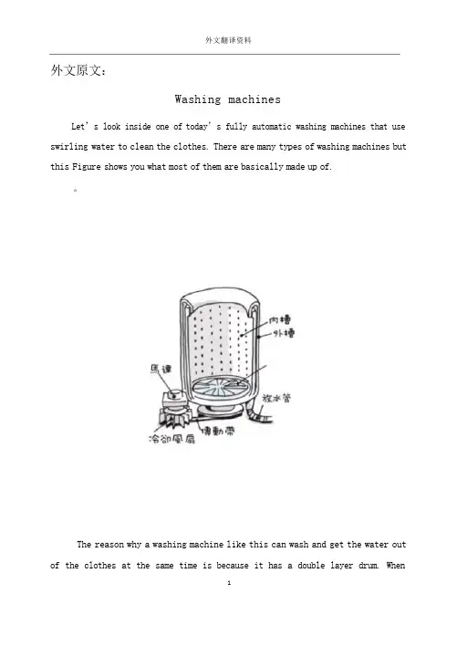
外文翻译资料外文原文:Washing machinesLet’s look inside one of today’s fully automatic washing machines that use swirling water to clean the clothes. There are many types of washing machines but this Figure shows you what most of them are basically made up of.。
The reason why a washing machine like this can wash and get the water out of the clothes at the same time is because it has a double layer drum.When1washing and rinsing,the pulsator spins and makes the water swirl..To get the water out of the clothes, the inner wall f the drum spins and the water goes through the holes.These days,the“centrifugal force washing machines”are quite popular.This type of machine does not use a pulsator.Instead,the inner wall spins really quickly.1外文翻译资料When the drum spins,the dirty clothes get stuck to the wall.The water and detergent also try to escape through the holes of the wall but before they do so,they are forced to escape through the clothes.When this happens,the power of the water and detergent removes the dirt form the clothes.Another good thing about this type of machine is that clothes don’t get tangled up so you don’t have to worry about your clothes getting ripped or damaged.Next,let’s look at some different types ofwashing machines!Many of you probably think that the water inside washing machines goes round and round. Actually, different washing machines make water flow in different ways.Whirlpool type:This type of washing machine uses a pulsator to force the water to move like a whirlpool inside the Drum.The spinning water forces the dirt out form the clothes inside the machine. Some of the newer models of this type also make the whirlpool move up and down to make it clean clothes even better!Agitator stirring typeThis type of washing machine has something that looks like a propeller at the bottom of the tub.This Propeller spins around and stirs the water.The water then forces the dirt out from the clothes in the machine.The good thing about this type of machine is that clothes do not get tangled up and clothes get evenly washed.Drum type:This type of machine has a drum with many holes in it. There are also protrusions bumps on the wall of the drum.As the drum turns,the clothes are picked up by the protrusions. When the clothes fall down from the top of the drum through the water,the movement removes dirt from the clothes.Centrifugal force type:2外文翻译资料As we have said before, the spinning drum pushes the water and detergent out through the wall of the inner drum. The power that comes form spinning the drum is called centrifugal force., which is where the name comes from. The water is forced through the clothes and then the holes in the inner wall.After one cycle,the water is recycled back into the tank and the process starts again.This cycle is what cleans the clothes!In Japan,people first started using machines in1930.But then the price of a washing machine was so high that most average persons could not buy one for their homes.Looking back now, there was something strange and funny on some of the first versions of the washing machine .The machine had two rollers that were used to sandwich each shirt and other clothes to squeeze the water out of them.The rollers were turned by hand,and in fact,you needed a lot of strength to turn those things!Still,people then thought it was a really neat invention!This type of water squeezer was used for almost 30 years until something new came along. The spin drier that used“centrifugal force”to get most ofthe water is out of the clothes.In1953,the nozzle type washing machine was first sold in Japan.This washing machine is like the older brother of the swirling washing machine that you see today. The price of these washing machines was lower and because of this, more people bought them. The first fully automatic washing machine was introduced in1968,and after that,washing clothes became a lot easier to do!There are a lot of different types of washing machines. What kind of washing machine do you have in your house?Fully automatic:The fully automatic machine has two drum layers that wash, rinse and removewater from clothes together. All you have to do is add detergent and put in dirty3外文翻译资料clothes and then washing machine will do the rest.There is also a new type of fully automatic washing machine that can dry clothes after they have been washed.Twin tub:This washing machine has one part that dose the washing and another part that does the squeezing.Even though it’s a hassle to take the clothes out and move them to other tub,the good thing is that you can wash and squeeze at the same time with one machine.Front loading:The main feature of front loaders is that they use a lot less water than other types.This is the type of Washing machine that dry cleaners use but a lot of people in western countries have this type of washing machine in their homes too.Let’s try to make the best washing machine in the world!We should already thank the scientists that invented the fully automatic washing machine because it makes washing clothes a piece of cake.Scientists are still trying really hard to find ways to make washing machines a lot handier to use for everyone.Some of the things that they are trying to do are to find better ways of making clothes clean and ways to make washing machines last longer.There are washing machines with d trying function today so you don’t even have to hang clothes after words because it dries them automatically!Amazing!Scientists are also trying to find ways to use less water and less detergent in washing machines at present.This is because that it is better to use less water for preserving the environment.What are washing machines of the future going to be like? Maybe there will be a washing machine that dries and folds your clothes after washing them,or maybe there will be one that will wash your clothes while you are still wearingthem! How handy would that be! Remember, if the first washing machine was like4外文翻译资料a dream to people in the old days, all the dreams you have about washing machines of the future may come true!Now, washing machine is becoming more and more popular. We see the main classification.Washing machine can be divided into automatic type and semi-automatic type two kinds, automatic type washing machine as long as we begin our work proactively set better washing procedure,washing machine began to work until the end without manual intervention. And semi-automatic washing machine washing and dewatering process is divided,is also called the double barrel washing machine, a tong,one takes off a bucket,and put tong inside washing out to artificial add to take off in the barrel dehydration is handled and complete laundry process.Full-automatic washing machine in structure to take off in tong internal bucket suit, two barrels of axis,while working with the clutch to finish washing state and dehydration of the transition of the states,on the key said is automatic washing machine.Full-automatic washing machine press catharsis means to points,can be dividedinto bunt washer and roll barrel type two kinds of washing machine, From the electric control ways to points,can be divided into mechanical program-controlled type and computer board controls type washing machine two kinds.The cylinder and the pulsator washing machine are now the main two kinds.Pulsator washing machine working principle is to add clothing,then open the inlet valve,choose good bibcock of water level and correct working procedures, switch on the power,closed warehouse door,and safety switch closed at water level,the public internal switch contacts are and dehydration contacts are interlinked,inlet valve electrify water,when the barrel water reaches the specifiedheight,in air pressure under the action of water level switch inside public contacts5外文翻译资料disconnect dehydration contacts and connect washing contacts,feed valve power to stop water,motor power is switched on,motor started running,and periodically sometimes are turning,sometimes reverse,mutual alternant,driven by clutch BoLun using the same cycle are turning,inversion,with a certain speed rotating BoLun can drive inside bucket of water and clothing,clothing rotating water formed in the mutual friction and reach the purpose of laundry. When washing process is completed,drainage electromagnetic valve electrify work,drain valve is opened,inside bucket of water exudes,and linkage shaft also the clutch from washing state switch to dehydration state,when drainage is completed,atmospheric pressure drop and inside bucket of water level switch public contacts reset through dehydration contacts,drainage electromagnetic valve keep electrify state,motor driven off running electrify bucket high-speed andjilt dry clothing,laundry program after washing machine disconnect hydropower and stop. As for intermediate process of how many times, laundry to wash the length of time, by process control.Roller-type washing machine of the principle and Pulsator washing machine are basic similar.But110mm drum machine it no clutch variable speed,but its motor is double-speed motor, so when washing machine work in washing state, program-controlled device connected motor washing low-speed windings, motor speed slow, working on dehydration, when they connect dehydration modal high-speed windings,motor high-speed operation,this process is programmed through the device and motor to work together to finish.To sum up, the role of these two kinds of washing machine is same, but different implementation,each has his strong point,Pulsator washing machine is simulated handmade kneaded action to work, 110mm drum type washing machine is by gravity inertial function to finish our work,they realize washing and6dewatering way also have different features,Pulsator washing machine to wear clothes is relatively large,but detergents degree is higher,110mm drum machine for clothing wear small,but detergents degrees,but lower than Pulsator washing machine to save water.So far,washing machine is still towards a higher requirements development.7译文:洗衣机来看一下涡流式全自动洗衣机的构造。
机床CNC系统的智能数控程序处理器外文文献翻译、中英文翻译
An intelligent NC program processor forCNC system of machine toolYadong Liua,_, Xingui Guoa, Wei Lia, Kazuo Yamazakia,Keizo Kashiharab, Makoto FujishimabAbstract NC program interpreting is one of the most important tasks of CNC in machine tool system. The existing CNC systems only supportvendor-specific NC program input, which restrict the applying of other similar functional NC programs with different program format.Especially for those users owning several machine tools with different CNC from the same provider, the diversity of NC programsdramatically increases their cost and time on operator training and machine tool maintenance. In order to deal with the variety of NC program, an intelligent NC program processor (NCPP) is proposed in this paper.1. IntroductionIn the CNC system of modern machine tool, NCprogram interpreting is very important, which is in charge of the accurate resolving of machining intention generated from CAM system. The major function of NCPP is to decode the input into motion command and programmable logiccontroller (PLC) command, and send them to the motion control processor (MCP) and PLC of CNC separately in order to control the movement of the cutting tool and auxiliary machine logic. Most CNC systems can handle only one specific NC program format, while the diversity of NC programs always entangles the machine tool users,especially for those owning several machine tools with different CNC but from the same provider.2. Interface of NC program processorNCPP is one module of the CNC, which requires cooperation between different modules; therefore it’s quite necessary to clarify the interface before starting design. The purpose of NCPP is to translate the input NC program into machine instruction, such asmotion command, PLC command or simple parameter settings and error messages. NIST calls these outputs as Canonical Machining Functions.The canonical machining functions were devised with two objectivesin mind:_ All the functionality of common 3- to 5-axis machining centers had tobe covered by the functions; for any function a machining center can perform, there has to be a way to tell it to do that function._ It must be possible to interpret RS274-compatible NC program into canonical machining function calls.3. Conceptual model of proposed NCPPCompared to the traditional design, the major feature of this NCPPis the structure with separation of NCSD and processing engine.Within thisNCPP, different NC program could be interpreted in terms of different NCSD, while the processing engine keeps the same. For example, suppose the input NC program follows Fanuc specification, the engine will refer to the Fanuc NCSD to do interpretation. Next time, if a NC program following Mitsubishi specification is given, the same engine will refer to the Mitsubishi NCSD to interpret it. For the two cases, it can be seen that each time only different NCSD is chosen, while the processing engine does not change. Such a solution provides dramatic flexibility and stability for the NCPP development, only one set of software code of the processing engine needs to be maintained. Even if there is an input NC program following a NC specification which is not available in the existing NCSDs, a new NCSD can be generated and added easily without recompiling the source code of the processing engine..4. Design of proposed NCPPBased on the conceptual model of the proposed NCPP If looking inside the NCPP, the key portion is the interpreting (processing) engine mentioned before, from a compiler’s point of view, the engine can be divided into four steps in order to check and decode an input NC program.These four steps are:_ Lexical analysis, which checks the character-based error within a NC program._ Syntax analysis, which makes sure the logic relation within each block of NC program is correct._ Semantic analysis, which checks the inter-block logic correctness of a NC program._ Optimization and code generation, which decode block and generate the canonical machining functions.4.1. Lexical analysisThe major functionality of lexical analysis is to merge a sequence of characters from the input NC program intosequence of words, which is a high-level representation unit,Meanwhile, in this step, all blank and comments within the program will be deleted. After lexical analysis, a symbol table with the same information but more systematic compared to the original character-based program will be built. During analysis, all character-based error will be checked, for example whether the unacceptable address letters has been used or not. In this paper, one dictionary has been designed in this step to store all the valid address letters.4.2. Syntax and semantic analysisSyntax analysis is to determine if a sequence of words within a block is syntactically correct, it is also called intra-block check. It includes the range checking of the data portion of a word and the parameters format checking.Semantic analysis checks the major inter-block error,which means tomake sure whether the logical relationship among several blocks of NC program is correct or not, for example, the same group G/M word cannot appear more than once in a block; block/word sequence should be subject to the G/M word execution order table, spindle should be turned on before any cutting motion starts, etc.In order to design NCSD for syntax and semanticanalysis, three kinds of cases of NC blocks should be analyzed:Case 1: Extract data expression in each word of NCprogram. For example, ‘‘X [1+2_3–4/5], Zsin[30],#1 2.0 F #1’’ should be correctly decoded as ‘‘X6.2, Z0.5, F2.0’’. Case 2: Check syntax relation of words within each block. For example, within block ‘‘G17 G02 X10 Y20 I-10F15 S100 M03’’, Z-axis value should not appear since in_ Terms with quote symbol as header and ender are terminal symbol._ Interpreting an expression is to apply one or more of the syntax rules.NC language can be considered as one type of simple computer programming language; therefore it’s quite reasonable to use EBNF to represent the NC program syntax. Based on that, the structure of NCSD can be systematically defined.4.3.1. Syntax representation using EBNFBased on these EBNF representations, case 1 mentioned in Section 4.2 can be easily solved. The fig shows an example of how to interpret word ‘‘X[1+2_3–4/5]’’ using these EBNF representations, as shown in this figure, two stacks (first in last outFundamental EBNF representation of NC languagemechanism) are used: value stack and operator stack. The operator stack is subject to a rule: the priority of each item is always in a decreasing order while the execution with highest priority always happens first. Following is the ordered operation list of interpreting:(1) Apply first EBNF rule defined, read the symbol ‘[’ and push it into the operator stack.(2) Apply EBNF rule 2,1,7,9 in turn, read value ‘1’ and symbol ‘+’, and then push them into value stack and operator stack, respectively.(3) Continue to apply rule 1,7,9 twice, read ‘2’/‘3’ and ‘*’/‘_’ separately, and push them into corresponding stacks.(4) Since operator ‘*’ on the top of the operator stack has higher priority than its previous one ‘+’ and higher than the current one ‘_’, current value 3’ is used to execute multiplication with ‘2’ popped up from the value stack. The result is pushed back into the value stack, while current operator ‘_’ is pushed into the operator stack.(5) Continue the quite similar operation as above mentioned until the operator stack is empty and the last value ‘6.2’ is popped up from the value stack.(6) The last value ‘6.2’ is the final result. Therefore, ‘‘X [1+2_3–4/5’’ is interpreted as ‘‘X6.2’’.For case 2 and 3, Fig. 9 gives the EBNF representation of a general NC block while Fig. 10 shows partial syntax EBNF representation of each G/M/F/S/T word in a group manner.Let us use a NC blocks example shown before in Section4.2 to explain how these EBNF rules are being applied. For each block of the following example:‘‘N0010 G91 G40N0020 S100 M03N0030 G01 G53 X20 F15’’EBNF rules B.1 in Fig. 9 will be firstly applied, and then the detailed word EBNF rules in Fig. 10 will be applied. Now for the first block, assuming the default modal is G01, the rule 1, 2 and 6 of B.1 will take effective, then in rule 6 of B.1, rule B.3 is applied further and a correct check result will be returned. The similar procedure will be done for the second block. Then for the third block, as rule B.3 is applied, rule 4 of B.2 will be applied too, which is (G53_Expr ‘g53’+ABS_Mode+G40_Expr+‘g00’|’g01’). In this rule, ‘ABS_Mode’ (‘g90’) is required when ‘g53’ isEBNF representation of G/M word. given with ‘g01’, however, the third block does not satisfy this rule because ‘INC_Mode’ (‘g91’) is effective (this is given in the first block); therefore a syntax error is found.4.3.2. Syntax dictionary implementation using tool command languageThe above-mentioned EBNF-based syntax of NC program is programmed using tool command language (TCL), one kind of script language which works in an interpretive execution manner instead of compiling way. As all the NC program syntax is represented using TCL as TCL procedures, it will be loaded to work as the syntax dictionary of NCSD in the proposed NCPP.4.4. Processing engine design4.4.1. Conceptual model of processing engine. An event generator and an embedded TCL interpreter are involved to handle each input NC block in terms of the loaded syntax dictionary of NCSD.The event generator triggers the TCL interpreter by extracting words within a NC block according to priority.For each word’s syntax, a corresponding TCL procedure defined in syntax dictionary will be called by the TCL interpreter. The Syntax and semantic analysis will be done during this process; canonical machining functions will be generated too. The dictionary generator in this figure is used to generate the syntax dictionary from NC program syntax EBNFrepresentation whenever a new NC specification is given.4.4.2. Processing flowThe fig shows the complete processing flow of proposed NCPP using one NC block example:(1) Initialization of the environment, which involves initializing parameters of NCPP (such as tool information, tool offset, coordination origin etc), loading the NCSD and starting the embedded TCL interpreter(2) Suppose one block ‘‘N10 G94 G01 G90 X2 Y4 F5 M03 ‘‘is ready to process.(3) NCPP processing engine search for the WORD with highest priority within this block in terms of the priority rules table. In this case first is word G01 and second is M03. As shown in the figure, priority rules table gives the definition of priority of words as they explicitly appear in the same block. Basically, group 1 of G word has the highest priority, followed by group 0 and other groups. For example, if G01 (group 1) and G92 (group 0) both given in a block, G01 should be taken care first. In the same sense, G words precede F, M and T words. In addition, modal information has the same effect, which means that the G modal word from higher priority group takes effect, as there is no G word explicitly appearing in the block.5. Prototype system implementationSo far, a prototype system of proposed NCPP has been implemented using C and TCL. This prototype was developed based on an existing RS274NGC interpreter written by Thomas Kramer from NIST in 2000. The current version realized almost all the functionality proposed in this paper, while the dictionary generator of NCSD is still under developing. By using the standard RS274 and Fanuc specification NC program as input, the result of the developed prototype system shows that a successful design was obtained. After being processed by A NC program example with syntax errors proposed NCPP, two syntax errors are both detected out with error messages, as those shown in the fig in italic and bold fonts. The corresponding canonical machining functions of the given NC program are generated too.6. ConclusionAn intelligent NCPP is proposed for the CNC system of machine tool. It has separated NCSD and processing engine. NCSD varies in terms of different NC program format, while the engine is fixed. Based on this new structure, it is easy to adjust the CNC system to adapt to various NC program format by only updating the corresponding NCSD in NCPP. In this paper, the NCSD has been designed by using EBNF and implemented as TCL procedures.AcknowledgementsThe authors wish to express their sincere appreciation for the generous support from Mori Seiki Corporation which makes this research possible. We also owe our thanks to the work of Dr. Thomas Kramer from NIST, whose work laid a great foundation for this research project. Further readin g[1] Vickors GW, Ly MH, Oetter RG. Numerically controlled machine tools. Chichester, UK: Ellis Horwood; 1990.[2] Peter S. CNC programming handbook. Industrial Press; 2000.[3] Karen AL. Fundamentals of compilers—an introduction to computer language translation. Englewood Cliffs, NJ: Prentice-Hall; 1992. [4] Thomas RK. The NIST RS274/NGC Interpreter—version 3, ISD of NIST; 2000.[5] Frederick MP. Canonical machining functions, ISD of NIST; 1997[6] Ronald M. Writing compilers and interpreters—an applied approach; 1991.[7] ISO/IEC 14977:1996(E) The standard of extended BNF,1997.[8] John KO. TCL and the TK Toolkit. Reading, MA: Addison-Wesley; 1994.机床CNC系统的智能数控程序处理器Yadong Liua,_, Xingui Guoa 、 Wei Lia , Kazuo Yamazakia,Keizo Kashiharab,Makoto Fujishimab摘要NC程序编译是机床CNC 的最重要工作之一。
电机和传动部件外文文献翻译、中英文翻译
Motor and Drive PartsTIMING BELT REPLACEMENT1, Power source must be connected to machine and turned on. Turn the power disconnect/lockout switch to the “O” (OFF) position and lock out. Allow machine to come to a complete stop, then press the “I” (START) button and hold for two seconds to verify that the machine will not start.2, After the green guard locking switch status light illuminates (when all rotating parts are idle) rotate the latch handle on the gear compartment door and open the gear door.3, Remove the belt guard by removing the hand knob that holds the guard (inside the gear compartment).4, Loosen the two pinch fasteners in the jack shaft spindle assembly (Figure 50).5, Loosen the motor mounting fasteners and slide the motor to release belt tension. Remove the belts (Figure51).Figure 50—Loosen pinch fasteners in jack shat spindle assembly (1) Pinch Fasteners,(2) Jack Shaft Spindle AssemblyFigure 51 – Timing Belts(1)TIMING BELT TENSION1, Use the motor tension wrench to slide the motor and apply tension to the timing belts. The pin on the wrench fits in a hole on the support housing(Figure52). The pinch fasteners in the jack shaft spindle assembly must be properly tension both belts. Tighten the motor mounting fasteners, and then tighten the pinch fasteners in the jack shaft spindle assembly.Figure 52 – Using the motor to apply belt tension. (1) Motor Tension Wrench2, Replace belt guard and tighten with the hand knob.3, Close and rotate latch handle connecting the gear compartment door and support housing.Electrical AssemblyINSPECTIONW ARNING: In the event of an electrical problem, only a qualified electrician should inspect or repair the fault. Voltages dangerous to life exist in the starter enclosure! The power disconnect/lockout switch must be in the “O”(OFF) position. Live voltages are still present in the box even though disconnect is off. Always disconnect and lock out power source before beginning electrical inspection or repair.The electrical assembly must be in good working condition before operating this machine. For a description of the amplifier and safety switch operation and method for checking this system. Electrical schematics are located in the starter enclosure. Refer to Figures53 and 54 and inspect the following:Figure 53 –Starter enclosure interior with variable frequency drive. (1) Disconnect Switch, (2) Guard Locking Switch Power Disconnect, (3) Main Fuses, (4) Earthing Terminals, (5) Transformer, (6) Transformer Fuses Block, (7) Variable Frequency Drive, (8) Contactor, (9) Standstill Monitor, (10) Control RelayFigure 54 – Starter enclosure interior, across-the-line start. (1) Disconnect Switch, (2) Guard Locking Switch Power Disconnect, (3) Main Fuses, (4) Earthing Terminals, (5) Transformer, (6) Transformer Fuse Block, (7) Overload Relay, (8) Contactor, (9) Standstill Monitor, (10) Control RelayStarter enclosure: Inspect interior of starter enclosure for corrosion. If a significant amount of water accumulates in the bottom of the starter enclosure, check the breather drain. Breather drain should be free from obstruction. Excess water could also indicate an opening or loose fitting that allows water to enter the enclosure. Check all access points to the enclosure. Check gasket around door and window. Inspect push/pull stop button, “I”(START) push button assemblies, selector switches and pilot light assembly for damage or corrosion. Replace rubber boots and pilot light lens if damaged.NOTE: Electrical components that fail due to water or chemical contamination are not covered under the warranty.Fuses: Remove transformer fuses, located in the transformer fuse blocks. Check with an ohmmeter or continuity light. If one fuse is replaced, all others of that type fuse should also be replaced.Machines equipped with variable frequency drive(VFD):The drive currently in use is the GPD315/V 7. If the digital display on the drive is not illuminated when the machine is energized, contact Urschel Laboratories.Standstill monitor: Terminals should be tight and free from corrosion. Monitor must be replaced if damaged.Power line filter (CE compliant machine with VFD): See the electrical assemblies illustrations in the “Parts” section of this manual for part locations.Guard locking switches:Replace or straighten actuator key if it is damaged or bent. Check cords for cuts or abrasions. If the green guard locking switch status light does not illuminate when power to the machine is connected, contact Urschel Laboratories. Switch must be replaced if it has been forced open while locked. Use only new screws that are supplied with the switch. Manual release must be in “lock” position when removing and replacing lid( Figure 55).Figure 55 – Guard Locking Switch. (1) Green Guard Locking Switch Status Light, (2) Guard Locking Switch Manual ReleaseGreen status light must be inside the lens when replacing the lid. To maintain watertight features, securely tighten the seven screws for the lid until there is no gap between lid and switch assembly. Do not over tighten.NOTE:The two screws located under the lid on the guard locking switch act as special dowel pins locking the switch assembly into place and must not be substituted.Interrupt switch: Terminals should be tight and free from corrosion. Recommended torque is 5.0 inch pounds (80 inch ounces) or 0.56 Newton-meters. Check sensor, actuator and cord for damage. Switch should be replaced if any defect or damage is defected. Check switch alignment. Actuator must be aligned and within 1/32 (8mm) of sensor to complete safety switch circuit (Figure 56).WARNING: Always perform the guard locking/interrupt switch system test before operating the machine.Figure 56 –Interrupt switch sensor and actuator must be aligned and within 1/32”(8mm). (1) Sensor, (2) ActuatorV ARIABLE FREQUENCY DRIVE PROGRAMMINGA replacement variable frequency drive must have frequencies programmed after the drive has been installed into the electrical enclosure. Refer to the “Speed Chart” on your machine or on page 30 in this manual and program the replacement unit according to the following procedure.WARNING: Starter enclosure must be energized in order to program the drive. Voltages dangerous to life exist when equipment is open and energized! Only a qualified electrician should inspect, install, or program variable frequency drive.1, Turn power disconnect/lockout switch to “O”(OFF). Open starter enclosure door. Operate the power disconnect/lockout switch mechanism in the enclosure to turn power on.2, Set the selector switches to the first drive frequency to be programmed. The frequency drive has a digital operator with a display (Figure 57). The display for the GPD 315/V7 drive will read the lowest setting allowed.Figure 57 – FPD 315 Drive, digital operator. (1) Digital Display,(2) Numeral Change Key, (increase), (3) Numeral Change Key, (decrease), (4) Read/Write Key3, Enter the speed in the display in hertz. Increase or decrease the value with the “numeral change” keys. See the chart for frequency settings.CAUTION: Do not attempt to over speed the motor! Over speeding could create a safety hazard and cause excessive wear on machine parts. Under speeding will cause the motor to overheat.4, With the value correctly displayed and flashing, press the “DATA/ENTER” or “ENTER” key. The display will stop flashing, indicating that the value has been entered.NOTE:Altering preprogrammed speeds will permanently change these values. To return to original settings, follow steps 1-4.5, Operate the power disconnect/lockout switch mechanism in the enclosure to turn power off. Close and lock starter enclosure door.Knife CareKNIFE CARE GUIDELINESKnives should be inspected and sharpened or replaced at regular intervals depending upon operating conditions, type of product and hours of operation. Follow these guidelines for bestresults:1, Do not attempt to remove all defects from the knife edge by sharpening.This practice results in shortened knife life. Small defects will not affect knife performance.2, New knives should not be installed beside worn knives. This arrangement may result in poor quality cuts. Keep all the knives from one spindle in a set and sharpen them together. Periodically check knife width or diameter to make sure all the knives in a set are the same size.3, Recommended minimum dimensions: The following minimum dimensions are intended to give satisfactory results for most applications. However, each customer must look at the quality of cut on his product to determine at what point knives are resharpened beyond usefulness. The minimum dimensions stated are intended to give satisfactory results for most applications. Some customers may be able to give satisfactory results from knives ground smaller, but some may notice a deterioration in quality of out before the minimum size is reached. Measure crosscut knives from the cutting edge to the back of the knife unless otherwise noted; measure the diameter of circular knives unless otherwise noted.SHARPENING EQUIPMENTUrschel Laboratories manufactures machines to quickly and efficiently sharpen knives. The following machine are available;Model WG honing machine is used to sharpen slicing knives and crosscut knives (straight cut only). For the Model DC, use workrest 33224 for 42281 and 42446 crosscut knives and slicing knife insert .Use workrest 33225 for 42460 crosscut knives. Use workrest 33256 for all other slicing knives.Model CKG honing machine is used to place the best possible edge on circular knives. The Model CKG can be purchased from the factory ready to sharpen 3-1/2”circular knives for the Model DC. Honers that are not set up to sharpen 3-1/2” circular knives must have certain parts installed. Use the following procedure:W ARNNING: Honers place an extremely sharp edge on knives; handle knives with care!1, Make sure the honer is unplugged from the power source.2, Install hone assembly, knife holder hub and edge roller stud for 3-1/2’’circular knives (Figure 58). The hone assembly (part number 33083) contains the hone bracket and internal parts, the shield and the honing wheel. The stud on the hone bracket is installed in the second hole from the motor shaft (4” knife position). The knife holder hub (part number 33081) is installed with the raised diameter facing out. The edge roller stud (part number 33023) is installed with the set screw in the second spot drilled hole from the outside end (Note that this part number has remained thesame but the part has been modified. The stud should have four spot drilled holes.) 3, Position the hone shield in as far as possible by loosening the screw and sliding the shield. Retighten the screw.4. Pull the knife clamp hub out of the clamping position. Hold a knife against the knife holder hub. Loosen the set screw in the motor shaft hub and slide the hub and knife on the motor shaft until the knife just touches the honing wheel. Tighten the set screw.5, Adjust the knife clamp if necessary. The knife clamp should hold the knife against the hub tight enough so that it cannot be rotated yet not so tight that it drives the motor back and distorts the base (the brake arm assembly must be properly adjusted to test for knife rotation). To adjust the knife clamp, loosen the two locking nuts and move the clamp in or out.6, Place a knife in the honer and sharpen in the normal manner (see the Model CKG instruction manual for more information). If too much of the knife edge is removed, readjust the hub. If insufficient metal is removed, loosen the screw on the hone shield and slide the hone slightly forward against the knife edge.BUFFINGWARNING: Only qualified trained personnel should buff knives. Use adequate eye and respiratory protection, and a properly guarded buffing wheel. Hold knife securely. Never attempt to catch a dropped knife! Should you drop a knife during the buffing operation, move away and let it tall.When crosscut knives are sharpened by grinding, filing or honing, a slight wire edge may be produced. Buffing will remove this wire edge.Install two to four 10" (254 mm) diameter buffing wheels side by side between flanges at least2" (51 mm) in diameter. Buffing wheels and bars of buffing compound are available from Urschel Laboratories (see “Tools", page67).Turn on the buffer (3600RPM) and hold the bar of buffing compound firmly against the outside diameter of the buffing wheels to apply alight coating of compound. Apply compound frequently to obtain sharp edges quickly.NOTE: If excess compound is applied, the wheel will harden, making it ineffective.Should this occur, Use a buffing wheel rake, available from an industrial supplier, to soften the wheel.When holding knives, be cautions and use a firm grip. Hold the knife firmly with the bevel side up, parallel with and just below the center line of the shaft of the buffer (Figure 58). Push the knife edge into the buffing wheel, penetrating the wheel 1/16"-1/8"(1.5-3mm). Move the knife endwise and buff the entire edge across the buffing wheel with a steady rapid movement in each direction. Several rapid passes are better than one or two slow ones. Do not hold the knife in one area of the buffing wheel too long as the edge may heat and burn. If a burr or wire edge remains, turn the knife over and buff with the bevel side down. Continue buffing, switching from side to side, until wire edge or burr is gone.Sharpen all sides of crinkle knife edges by tipping the knife endwise at a slight angle, first in one direction and then in the other. Next, the knife is held straight and level to buff the remainder of the cutting edge.With bevel side up, sharpen side surface of crinkle knife edge by tipping the knife endwise at a slight angle, first in one direction and then in the other. Next, the knife is held straight and level tobuff the remainder of the cutting edge.Figure 58 –Model CKG honing machine set to sharpen 3-1/2”circular knives (1) Hone Bracket, (2) Mounting Position for Hone Assembly, (3) Knife Holder Hub, (4) Set Screw,(5) Edge Roller Stud (set screw seats in second hole), (6) Hone Shield, (7) Screw, (8) Knife Clamp Hub, (9) Locking Nuts, (10) Honing WheelFailure to obtain sharp edges by buffing may be caused by the following:1, Edges may be too dull or blunt. Blunt edges must always be ground or filed to restore a bevel width and angle similar to that found on a new knife.2, Knives must be correctly held against the buffing wheel (Figure 59).3, Too little or too much buffing compound on the wheel.4, Undersize buffing wheels. Discard the buffing wheels when they are worn to8-3/4" (222 mm) diameter.Figure 59 – Correct position (top) and incorrect position (bottom) for knife during buffing .(1) Knife, (2) Buffing WheelPROBLEM CAUSE CORRECTIONMachine Does Not Start Power disconnect lockout switch isin the "O"(OFF)positionTurn power disconnect lockoutswitch to the "I"(ON) position. Manual release on either of theguard locking switches is in the"unlock" positionTurn manual release to the"lock" position on bothswitches, page 17.Guard locking switch powerdisconnect is in the"O"(OFF)positionTurn guard locking switchpower disconnect to the"I"(ON) position, page 54.Push/pull stop button is not pulledout after being pushedPull push/pull stop button out,page 28.Covers and guards not securelyclosedMake certain covers andguards are securely closed.Check for bent or twistedbrackets that will preventswitches from lining up. See"Covers and Guards",pages34-35.VFD fault or warning Not error code displayed onVFD. Turn disconnect off.电机和传动部件同步带置换1,电源必须与机器连接并打开。
减速器论文中英文对照资料外文翻译文献
减速器论文中英文对照资料外文翻译文献What is a Gearbox?A XXX.1.The n of a Gearbox1) The gearbox ces the speed while increasing the output torque。
The torque output。
is the motor output multiplied by the n。
but it should not exceed the XXX.2) The gearbox also ces the inertia of the load。
which decreases by the square of the n。
Most motors have an inertia value that can be XXX.2.Types of GearboxesCommon gearboxes include bevel gear cers (including parallel-axis bevel gear cers。
worm gear cers。
and cone gear cers)。
ary gear cers。
cycloid cers。
worm gear cers。
XXX.mon Gearboxes1) The main feature of the worm gear cer is its reverse self-locking n。
which can achieve a large n。
The input and output shafts are not on the same axis or in the same plane。
However。
it generally has a large volume。
low n efficiency。
and low n.2) XXX and power。
It has a small size and high n。
外文文献翻译正文
PLC模块控制回转工作台在三轴数控铣床铣削螺旋伞齿轮中的应用S. Mohsen Safavi & S. Saeed Mirian & Reza Abedinzadeh & Mehdi KarimianReceived: 25 November 2008 / Accepted: 23 November 2009 # Springer-Verlag London Limited 2009摘要当今,数控机床在机电一体化领域中得到了日益广泛的应用。
机械、电气和数据处理系统与数控技术相结合,引领了新的生产加工理念。
近年来,数控技术的发展已将非线性校正技术在切削弧齿锥齿轮中的应用变为可能。
在本文中,我们将尝试采用带有外加PLC模块分度台的三轴数控铣床,运用带有索引工作界面的通用铣床的传统连续多重切削方法来加工制造出这个螺旋伞齿轮。
该研究包括(a)弧齿锥齿轮的几何建模,(b)运用CAD/CAE系统进行传统或新型非传统方案的模拟仿真,(c)数控加工工艺的设计与PLC编程,(d)通过三轴数控铣床的实验切削来探索新方案的正确性。
结果表明,开发的螺旋伞齿轮实验切削方案不仅与先进数控加工相比成本更低,而且相比传统切削,加工齿轮的时间也较短。
因此,在螺旋伞齿轮加工领域,这是一个很经济的方案。
关键词:齿轮加工,螺旋伞齿轮,CAD/CAM/CAE,数控技术,PLC,交流电动机,逆变,接近传感器,光电传感器,旋转编码器1 引言齿轮是工业机械领域中重要的精密机构,在平行轴、横向交叉或非交叉轴之间用于传递机械功率和机械运动。
虽然有时会看不见,但齿轮仍是我们工业文明中最重要的机械元件之一。
在各式各样的条件下,齿轮会以几乎达到无限的速率运转。
得到发展的齿轮加工设备与工艺流程已经非常先进与成熟。
无论大批量生产还是小批量生产,无论在小型车间还是分批处理的加工车间,加工齿轮的流程按顺序都需要以下四步操作:(1)下料(2)切齿(3)热处理(4)研磨根据它们的类型、应用范围及强度和刚度要求,通常经过铸造、挤压、锻造、粉末冶金、注塑加工和滚齿加工来完成齿轮的加工制造。
- 1、下载文档前请自行甄别文档内容的完整性,平台不提供额外的编辑、内容补充、找答案等附加服务。
- 2、"仅部分预览"的文档,不可在线预览部分如存在完整性等问题,可反馈申请退款(可完整预览的文档不适用该条件!)。
- 3、如文档侵犯您的权益,请联系客服反馈,我们会尽快为您处理(人工客服工作时间:9:00-18:30)。
附录A英文翻译 原文: Abstract: This paper presents a method of machining inner cavities of precision aerostatic bearings by NC synchro-rotary EDM. This method can easily machine the precision aerostatic bearing to give symmetry of 10um and the surface roughness of Ra0.4um. This paper analyses the principle and the condition of the technique, and introduces the machining apparatus and control system. Keywords: Aerostatic bearing Syncro-rotary. 1. Introduction Air bearing is developed with the emerging of high technology. It employs gas as lubricate so it shows extremely low friction and wear, no heat ph rotary precision, etc. It hasroducing, the hig been widely used in aerospace, precision machine tool, medical instrument and electronics industries (1,2).
The precision aerostatic bearing is one of air bearing with the highest rotary precision. Its special cavities are shown in Fig.1 Fig.1 the inner cavities of air bearing It is used in measuring appliances and precision machine tools. The symmetry of aerostatic bearing cavities is high, so it is difficult to be machined, specially taper or sphere cavities. In order to obtain high symmetry, general methods must employ special fixture with high precision index head. The methods show high machining costs and complicated operation for small serial production. On the basis of this condition, the condition, the synchronous rotary electrical discharge machining (SREMD) with NC system is presented. This method can easily machine the precision aerostatic bearing cavities with low machining costs. 2. The principle and advantages of SREDM The principle of SREDM is shown in Fig.2. Fig.2 the principle of SREDM During machining, the workpiece is a negative pole and the tool is a positive pole. The tool electrode turns at the speed twice of that of workpiece. At the same time, the slow feed in the vertical direction of electrode spindle is added. As the workpiece turns one cycle, the same point of facing two cavities. Because if the tool wear in one cycle is negligible, it can be considered that the two cavities are symmetrically machined by the just same point of the tool. The high symmetry of cavities is machined with low machining costs. The throttling slots in bearing can also be machined by the same way. The condition of SREDM is: D=2d 21
Where: D- the diameter of the cavity, d -the diameter of the tool electrode, 1- the angular velocity of the workpiece, 2- the angular velocity of the tool electrode.
The advantage of the technology are: (1) This method can machine conduct materials with any hardness, so the bearing can be quenched before being machined and the effect of quenching is eliminated. (2) The high stiffness machine tool is not necessary, because of no large cutting force in machining. (3) The simple shaping principle makes the process omit the fixture with high precision index head. (4) This method supplies the high symmetry precision. (5) The low roughness is obtained by this method. (6) By programming, this method can machine other complex surface of inner cavity. 3. Machining the cavity on WEDM machine tool by SREDM The SREDM can be achieved on a WEDM machine tool with adding two accessories, WEDM machine tool. The refitted machine equipment is showed in figure 3. Accessory 1 whose shaft is driven by stepping motor directly is fixed on the body of the machine tool. The electrode is fixed on the shaft. Accessory 2 whose shaft is directly driven by anther stepping motor is fixed on the worktable of the machine tool. The workpiece is fixed on the shaft. The two shafts are on the same horizontal plane and parallel with the X direction of the worktable. The tool electrode and the workpiece can rotate, and the wprkpiece can move in X or Y direction with worktable. To meet SREDM, we have developed a numerical control synchronous rotary system, in which stepping motor divided driving technology controlled with single-chip micro-computer is applied. Two stepping motors can rotate at any ratio of relative angular
12345
1-accessory1 2-tool 3-workpiece 4-accessory2 5-worktable Fig.3 the machine apparatus after refitted
velocity. They work accurately and steadily. The feed motion can be carried out by Y direction stepping motor of worktable. The main CPU of the system controls the feed motion on the basis of gap voltage, which is supplied by spark condition inspection block. The one pulse motion equivalent of the worktable is 1m and the stepping motor divided driving technology is added, so the system can exactly trace the spark gap during precision machining. This system is shown in Fig.4. 4. The process and the key of SREDM Before machining, the workpiece and tool electrode are adjusted to the positions which are shown in figure 2. The operation method of the technology is: At first, the two stepping motors that drive the rotation of workpiece and tool are started, then the machining fluids