WM10滚轮换向阀
重汽价格表

8 6 4 4 4 12 20 20 20 2 6 2 10 4 4 4 4 4 4 4 12 1 2 10 6 6 5 2 1 12 4 10 2 2 2 2 1 4 4 1 4 1 5 12 4 4 4 2
120.8 11.06 86.25 123.11 123.11 6.33 23.1 16.1 27.6 189 87.15 79.35 25.19 235.8 235.8 235.8 132.3 117.3 89.7 67.85 23.16 1,345.00 294 35.65 47.25 11.04 17.85 134.4 331.8 141.75 1,911.83 9.37 52.92 34.65 29.4 79.8 526.3 90.6 147.4 431.6 147 431.58 44.1 8.42 16.84 47.37 25.26 321.1
重汽价格表
图号 190007301050+001 190007301050+002 199012340005 199012340029 199012340121 AZ9007300004+001 AZ9007300004+002 AZ9007300102+001 AZ9007300102+002 VG1540050032 VG1540050033 WG1642740010 190007331129+001 AZ1642820010 AZ9007330001 AZ9112530333 WG1642110024 WG1642340012 WG1642340013 WG1642340015 WG1642440021 WG1642440052 WG1642440082 WG1642820015 WG1642820017 WG1642820019 WG1664440068 WG9000360100 WG9000360101 WG9000360514 WG9000360522 WG9000360523 WG9000360524 WG9000360528 WG9000360602 WG9003884160 WG9100570014 WG9100583058 WG9232520010 WG9232520011 WG9631470075 WG9700240015 WG9716580021 WG9718710003 物料名称 订购数量 单价(元) GL-5 85W/90重负荷车辆齿轮油-18L 100 255 GL-5 85W/90重负荷车辆齿轮油-3.5L 60 55 太阳轮 (Z=23) 4 46.62 密封圈 40 3.78 内齿圈(Z=57) 2 169.5 20W/50 CF-4级柴油机润滑油(18L/ 200 239 桶) 20W/50 CF-4级柴油机润滑油(3.5L/ 90 51 桶 CH-4 级 20W-50 柴油机润滑油(18L) 120 329 CH-4 级 20W-50 柴油机润滑油(3.5L 72 66 进气门摇臂总成(共轨欧3/57) 12 22.05 排气门摇臂总成(共轨欧3/57) 12 22.05 雨刮臂总成 5 22.05 液压转向油 60 85 蒸发器总成 2 325 制动液 100 25.3 膨胀箱总成 2 124.2 右气体弹簧支撑栓 10 26.25 左门锁挡块总成 5 17.54 右门锁挡块总成 5 17.54 右车门锁体总成 5 41.21 横向稳定减振器总成 2 84 驾驶室锁止信号开关 10 18.9 后悬减振器总成(螺旋弹簧IV) 6 86.1 储液器总成 6 84 冷-储软管总成 6 57.16 蒸-压软管总成 5 161.3 驾驶室后减振器总成(空气弹簧) 3 756 24"膜片式制动气室(左) 8 73.5 24“膜片式制动气室(右) 8 69.66 弹簧储能缸 20 27.84 手制动阀 2 118.7 四回路保护阀 4 161.7 继动阀 4 87.15 挂车手制动阀 2 84.21 双膜片制动气室L=67 2 207.9 车轮螺母 50 3.02 停油缸 4 35.79 车速传感器 4 28.18 前簧左后支架 4 192.6 前簧右后支架 4 192.6 球铰接头总成 4 87.4 变速器换挡手柄及挡位标牌总成 2 71.4 电气接线盒总成 2 342.1 气喇叭电磁阀 6 24.15 备注
威索燃烧器中文说明书
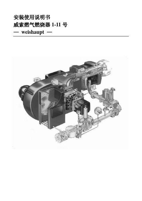
安装使用说明书威索燃气燃烧器1-11号—weishaupt —证明在此我们说明,威索(-weishaupt—)燃气燃烧器符合下列EC标准得基本要求:90/396/EEC Gas Equipment Guideline89/336/EWG Electromagnetic patibility73/23/EEC Low Voltage Guideline因此燃烧器上带有CE/0085标记。
其它质量保证体系由DIN EN ISO 9001认可。
德国麦克斯·威索有限公司目录1、一般说明 (2)2、燃烧器得安装 (4)3、气路示意图 (6)4、阀门组件说明 (7)5、阀门组件得安装 (14)6、阀门组件得气密性检验 (17)7、功能流程检验 (17)8、准备第一次调试 (18)9。
调试 (18)10.燃烧筒及稳焰盘得调整 (28)11、工作范围表 (29)12、设置点火电极 (30)13、鼓风轮得固定 (30)14.工作流程 (31)15、限制及辅助开关得凸轮位置设置 (38)16、燃气流量得计算,从标准状态到实际状态得换算 (40)17、常见故障及排除方法 (42)1、一般说明简介下表为安装及调试中各个步骤得基本概括为了达到正确安装及调试得目得,请对此说明书中得所有说明加以注意。
步骤工作章节1 燃烧器得安装 22 安装燃气阀门组 53 燃气阀门组得气密性检验 64 检查燃气供气压力8、15 排去燃气阀门组中得空气8、26 功能流程检验77 检查燃烧头108 检查设备9、19 调试9、3 安全性要确保燃烧器得安全运行,必须由合格得专业人员按此说明书进行正确得安装及调试.要特别注意相关得安全规定(如DIN—VDE,DIN —DVGW)。
火焰监测装置、限制装置,调节机构以及其它安全装置只能由制造厂或其委托单位进行安装.不遵守规定可能导致人员伤亡及重大物质损失等严重后果。
人员资格本说明书所指得合格人员为熟悉安装调试并有足够能力从事其工作得人员,如:➢受过培训,并有能力根据安全技术得标准操作、接地及标识电器得➢受过培训,并有能力在现场对燃气装置进行安装、调试及维修得操作说明每台燃烧器所附得操作说明必须放置在设备周围显眼处。
TRANSTECH传动系统维修服务系统部件表说明书

Appendix C - PartsExternal Parts for the TRANSTECH Transmission Service System Please refer to the part numbers below when ordering parts for the unit.Part #DescriptionMV010-0027WheelMV010-0026Wheel Hub capMV010-6000Swivel casterMV010-6001Swivel caster with break lockMV010-5004Hose bracketMV010-0407Handle, steelMV010-6060Reservoir CapMV020-1003Harness, powerMV020-1002Harness, InternalMV020-0010Alarm buzzerMV020-003815 AMP circuit breakerMV020-0063Lamp, Ambar ½” mountMV020-0073Lamp, green ½” mountMV020-0090Relay ear mountedMV020-12003- position rocker ON/OFF switchMV020-1201Momentary rocker switchMV050-0056Regulator knobMV050-2700Fluid Level SwitchMV050-3200Output/Return Flow regulatorMV050-2901.2 - 2.0 Acrylic flowmeterMV050-1000Screen filter inline ½ MPT. Pp.MV050-3001Check valve, (disposal hose)MV060-5810Cap plug (handle)MV070-0086Hose, Nylon 3/8 OD.MV080-0230Female Quick Disconnect Couplers, 1/4”, NiMV200-8611Output/Return hose assemblyMV200-8612Disposal hose assemblyMV200-8613Solenoid #3 Assembly (If equipped)MV200-8614Solenoid #2 Assembly (If equipped)MV200-8615Solenoid #1 Assembly (If equipped)MV200-8616Pump AssemblyMV200-8617Fluid Tank AssemblyMV200-8620Rotoflow assemblyMV200-8204Operators ManualMV200-3100Adapter Kit (Standard)MV200-3101Adapter Kit (Deluxe)C-1Appendix C - PartsC-2 .(Complete) Control Panel AssemblyMV200-8618Elbow fitting; push typeMV030-4602Flow RegulatorMV050-3200Street TeeMV030-4400 RotoflowMV050-2900 Elbow fitting 020-1201MV030-4602RotoflowMV050-2900 Regulator Assy.MV050-3200Elbow fitting; push type Straight Connector FittingMV030-4602MV030-0043(Elbow fitting; compression type)MV030-3094Appendix C - Parts Return Regulator Assembly FlowmeterMV200-8621B MV050-2901Left Rotoflow AssemblyMV200-8620BLow fluid LampMV020-0063020-0063Drain Pan SwitchMV020-1200Power SwitchMV020-1201Service in Progresslamp. MV020-0073Right Rotoflow AssemblyMV200-8620AOutput Regulator Assembly FlowmeterMV200-8621A MV050-2901.C-3Appendix C - PartsC-4 .Pump Assembly MV200-8616Male Pushlock fitting Straight Compression fittingMV030-4601MV030-0044Male Electrical Conn.Shurflow PumpMV020-0042MV050-2400Solenoid Valve Shaft(Internal to Block)MV050-2310Slolenoid CoilMV050-2320Solenoid Block AssemblyMV050-2300Mounting PlateMV010-5412Appendix C - Parts Straight fitting Fill CapMV030-0044MV010-6060Fluid tank AssemblyMV200-8617Low Fluid Level SwitchMV050-2700Filter AssemblyMV050-1000Elbow fittingMV030-4402½” HoseElbow fitting (push lock type)MV070-0087MV030-4601.C-5Appendix C - PartsNOTE: If components are equipped with a “Press-on” fitting, follow the next steps.1. Press and hold hose to be removed firmly into the fitting.2. Press the Compression ring into the body.3. With compression ring pressed, pull the hose out of the fitting.When installing; Hose needs to be inserted into the fitting approximately 3/4 in., (0.75”), to esure proper seal onto the hose.PUSH INSERT FIRMLY INTO BODY, DEPRESSCOMPRESSION RING AGAINST BODY AND PULL HOSE.COMPRESSIONRINGBODYORDERING PARTSParts for the unit may be ordered by callingCustomer Service, have your model and serialnumbers available:in the U.S. International:(714) 555-4822Call your local distributor(800) 841-8810C-6.。
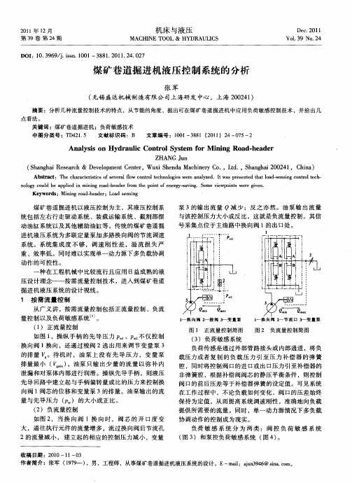
煤矿巷道掘进机液压控制系统的分析
( h n h i eerh& D vlp e t e t ,Wui h n aMahnr o , t. S a g a 2 0 4 ,C ia S ag a R sac ee m n ne o C r x S e d c ieyC . Ld , h n hi 0 2 hn ) 1
驱动系统工作时禁止操作油缸系统 ;反之 ,操作油缸 系统 时禁止 开动行 走驱动系统 。同时规定各油缸不得 同时动作 。因而可 以将左右行走驱动系统和油缸 系统 公用单一泵 源 ,取 消各 油缸 回路操作换 向阀的进 口压 力补偿 器 ,以减少 发热 、节约成本 。 ( )对于运 行不 够 平 稳 、惯 性 比较 大 ,存 在 减 4 速制 动过程 的 回路 ( 6 ,当制 动压力 高 于进 油 口 图 ) 压力 ,通过梭 阀 2与压力补偿器 4弹簧腔相通 的油压
导 阀,用于驱动主 阀的阀芯 ,而高 速开关 阀可用 由计 算机软件产生 的 P WM ( 脉宽调 制信号 ) 控制 ,这 样
21 0 1年 l 2月
机 床 与 液 压
MACHI NE T00L & HYDRAUL CS 1
De . 01 c2 1
第3 9卷 第 2 期 4
Hale Waihona Puke V0. 9 NO 2 13 . 4
DOI 0 3 6 /.sn 1 0 :1 . 9 9 j i . 0 1—3 8 . 0 1 2 . 2 s 8 12 1.4 0 7
量控 制 以及负荷敏感 系统 。 ( )正流量控制 1
1 换 向 阍 2 梭 阀 卜 变 量泵 一 一 l 挟 向 网 卜 节 流 口 3 变 量 泵 一 一
图 1 正流量控制简 图
图 2 负流量控制简图
8月1日统计的发动机上下场图号对照表

窄缸体ST/HW用 出水管 无570风扇 风扇 水泵总成(三角带) 无 620刚性风扇 风扇 ST/HW小马力 三角皮带(参图1614 090099 三角皮带(参图1614 090099 ST/HW大马力 62机选装硅油 硅油风扇(Φ570) 选装570硅油用 中间法兰 水泵总成(57) 无 中置风扇V 三角皮带 垫块(HOWO) 豪沃用 支撑块 豪沃发动机 45mm加宽机油泵 图号有误 机油滤清器总成 国二机型 窄缸体换装1.5kW发电机 拉紧螺栓 窄缸体换装1.5kW发电机 1500W交流发电机 机油压力传感器 老式传感器 1000W交流发电机 无 1.5kW发电机选用装置 拉紧块 固定板(HOWO) 豪沃用 固定板(HOWO47) 机冷座上,HW62/87/69 固定板 固定板(HOWO69/62/87) 机冷座上,HW62/87/69 固定板 窄缸体ST/HH/HY后取力用 增压器回油管组件 窄缸体ST/HH/HY后取力用 增压器进油管组件 压气机进气管总成 窄缸体豪运用 油封座 窄缸体用 油底壳总成(HH) 窄缸体黄河王子用 57机用 发动机前吊环(57) 57机用 发动机后吊环(57) 油气分离器组件(06版57机) 06版57机 骨架油封 四气门发动机用 出水管 国三共轨用 气门摇臂座(06版57机) 四起门发动机 排气门桥(共轨欧3/57) 四气门发动机用 机油滤清器组合件(欧Ⅲ) 国三共轨 燃油滤托架(精滤托架) 共轨国三 输油泵进油管 国三共轨 国III共轨 喷油器回油管总成 国III共轨 固定板 国III共轨 共轨组件回油管 国III共轨 柴滤回油管 国III共轨 高压油管组件(一) 国III共轨 高压油管组件(二)
停用 停用 停用 停用 停用 停用( 停用 停用 停用 停用 停用 停用 停用 停用 停用 停用 停用 停用 停用 停用 停用 停用 停用 停用 停用 停用 停用 停用 停用 停用 停用 停用 停用 停用 停用 停用 停用 停用 停用 停用 停用 停用 停用 停用 停用
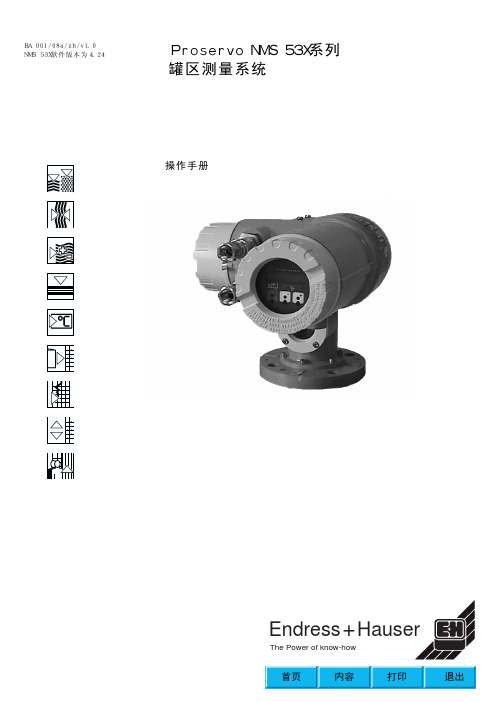
E+H 伺服液位计操作手册
不要绞缠或扭曲钢丝 小心操作 否则钢丝很容易损坏 不要用手拽钢丝来提升浮子 请通过操作仪表提升浮子 仪表动作时请不要触摸钢丝 钢丝弯曲半径不能小于50mm 若用户不小心操作 则我们无法确保测量钢丝的使用寿命
浮子的安装 仪表在发货时 测量浮子可能安装于仪表内或与仪表分离 * 测量浮子安装于仪表内发货时 请参照附带手册 取出填塞物 * 与仪表分离发货时 请将仪表安装在法兰口之前 把浮子安装到测量钢丝
2
一般注释
操作手册 本操作手册适用于预装V.4.24或以上版本软件的Proservo NMS 53X 在使用仪表前请认真研读并理解本操作手册 本手册仅用于描述仪表功能 未经许可 不能翻版 本手册可能会在无事先通知的情况下更改 请妥善保管本手册 若发现任何错误或有任何问题 请联系我们服务中心或 当地销售代理
9 浮子和测量钢丝.............27 9.1 形状 直径及材料 .......27
10 触摸控制和编程矩阵 ........................28
10.1 显示和操作单元 .......28 10.2 操作单元的动能 .......28 10.3 HOME 位置 ...........30 10.4 访问代码.............31 10.5 编程矩阵说明 .........32 1 0 . 6 编 程 矩 阵. . . . . . . . . . . . . 32 10.7 编程矩阵描述 .........41
通信
状态
0...2500mm/分钟 0...99秒 带背光LCD 两行显示 每行16个字符
(同时显示液位和温度) (语言日文/英文可选)
世伟洛克卡套接头手册
世伟洛克授权的销售与服务中心提供了 安装培训班, 这些培训班将在以下方面 提供更多信息:
■ 进行安全和无泄漏连接的要求
■ 与世伟洛克卡套管接头一起使用的各 种工具和附件。
腐蚀
世伟洛克卡套管接头有各种不同材质可 供选择, 其中包括化学性质受到控制的 316 不锈钢以及许多的其它合金, 这些材 料在各种不同应用中具有增强的耐腐蚀 性能, 其中包括酸气和海底系统。
世伟洛克进行的测试表明, 世伟洛克卡套 管接头有足够的能力承受热冲击和 高温。
若需了解关于热冲击测试报告的更详细 信息, 请联系您当地的世伟洛克授权销售 和服务代表。
符合工业标准
世伟洛克公司与全世界的标准规范组织 合作, 以便为您提供符合需要的产品。
有关世伟洛克卡套管接头所采用的制 造标准规范, 请参阅第 P 9 页的材 料; 第 P 9 页的螺纹规格; 以及第 P 10 页的压力额定值。
可定位支管, SAE/MS 直螺纹 (TTS) 和可定位支管, ISO/BSP 平行螺纹 (TTR), 39
与世伟洛克卡套管 接头对接的 Kwik 夹具式法兰, 42
卡套管转换接头
卡套管转换接头信息, 43
外螺纹
NPT 和 ISO/BSP 锥形螺纹 (RT), 44
ISO/BSP 平行螺纹 (RS 和 RP), 45
ASCO样本
4S H I P P I N G P R O G R A M Over 2000 of today's most popular products w w w.a s c o v a l v e.c o m4S H I P P I N G P R O G R AMDelivery, Quality, and Value are ASCO’s commitment to you. The ASCO Today program features a range of flow control and monitoring products available for shipment the same day you order them. ASCO guarantees †to ship any order received before 3 PM EST for up to 25pieces per product from this catalog the same day or ASCO pays the shipping costs. Orders entered after 3 PM EST will ship the following business day. (Saturdays, Sundays, and Holidays are excluded.) Orders for same day shipment cannot be cancelled or adjusted once entered.The products listed in this catalog provide the performance required for a variety of system and process applications including boiler, air handling, process control, and water and steam control. The control voltages available for each product are the primary voltages used in industrial and commercial applications today.We are committed to providing you with an unmatched level of customer service, quality, and reliability. The performance information shown is abbreviated to allow for easy selection of ASCO Today delivery products. If you cannot find the product you need or if you need more detailed specifications, visit , or call 800-972-2726.Find the valve that you are looking for in the provided tables. The tables provide information on the followingcharacteristics to help in making your choice:• Pipe Size • Orifice Size • Cv Flow• Operating Pressure Differential • Maximum Fluid Temperature• ASCO Catalog Number (for reference only)When ordering a Valve Product, simply supply the Valve Order Code x located in the table. Example: 20243When ordering a Rebuild Kit for a valve, supply the Rebuild Kit Order Code located in the table.Example: 302272If a replacement coil is needed for a valve, supply the Replacement Coil Order Code located in the table.Example: 238610-058-D*When ordering products other than solenoid valves, please supply the Order Code located in each table.• Body Material • Seal Material • Coil Voltage • Coil Wattage • Approvals†As industry requirements change, ASCO reserves the right to modify the contents of this catalog and program parameters without notification. Updates on this program can be obtained from the ASCO website or by calling 800-972-2726, or by contacting your local ASCO representative or distributor and referencing the ASCO T oday program.Solenoid valves with DC voltages have been highlighted in gray to simplify product evaluation. Definitions of symbols and abbreviations can be found on page 31 & 32 of this catalog.w w w .a s c o v a l v e .c o m • 800-972-2726CAUTION:Users should consult or Catalog 34 to see complete specifications for the product selected from this catalog.WARNING:Improper selection or use of products and related items in this catalog can cause death, serious injury,or property damage.!8009722726Refer to inside cover for ordering information.•General Service2-Way Normally Closed 1-62-Way Normally Open 72-Way Slow Closing 103-Way Normally Closed 11-143-Way Normally Open 11-143-Way Universal 11-144-Way Inline 15-174-Way NAMUR17•Plastic Body2-Way Normally Closed 33-Way Normally Closed13•Air Operated2-Way Angle Body Piston 82-Way Normally Closed 83-Way Normally Closed8•Hot Water/Steam2-Way Normally Closed 92-Way Normally Open 102-Way Slow Closing10•Cryogenic2-Way Normally Closed10•Group Mount2-Way Normally Closed 163-Way Normally Closed 164-Way Inline16•ISO Pneumatic4-Way Pad Mount18•Intrinsically Safe3-Way Normally Closed 183-Way Universal 184-Way Inline18•Low Power3-Way Normally Closed 183-Way Universal 184-Way Inline18•Manual Reset3-Way Universal 193-Way Low Power19•Valve Monitoring Systems (VMS)VMS20Accessories20•CombustionFuel Gas2-Way Normally Closed 212-Way Normally Open 222-Way Manual Reset 22Electro-Hydraulic 22-23Cable Release23Fuel Oil2 & 3-Way Normally Closed23•Dust Collector2-Way Pulse Valves242-Way Remote Pilot Valves 24Pilot Boxes24•Micro-Miniature2-Way Normally Closed 253-Way Universal25•Pressure/Temperature SwitchH Series 26P Series 27-28S Series 28Accessories28•AccessoriesFilters and Regulators 29Adjustable Flow Control 30Pipe Line Strainers30Quick Exhaust/Shuttle Valves 30Check Valves 30Din Connectors 31Electronic Timer 31Mufflers31•Prefix and Suffix Definitions 31•Coil Temperature Ratings 32•Abbreviation Descriptions32Refer to inside cover for ordering information.w w w .a s c o v a l v e .c o m • 800-972-2726Two way (2/2) general service solenoid valves have one inlet port and one outlet port.• Control of air, water, light oil, non-corrosive media• Normally closed (opens when energized) and normally open (closes when energized) operation • Size range of 1/8" to 3"General Service - 2/2 NC 1/8"1w w w .a s c o v a l v e .c o m • 800-972-27262Refer to inside cover for ordering information.w w w .a s c o v a l v e .c o m • 800-972-27263Refer to inside cover for ordering information.w w w .a s c o v a l v e .c o m • 800-972-27264Refer to inside cover for ordering information.w w w .a s c o v a l v e .c o m • 800-972-2726General Service - 2/2 NC 3/4"5Refer to inside cover for ordering information.w w w .a s c o v a l v e .c o m • 800-972-27266Refer to inside cover for ordering information.w w w .a s c o v a l v e .c o m • 800-972-27267Air operated valves are standard valves modified by substituting a piston operator in place of the solenoid. An air operated valve will operate the same as the solenoid version except that it is driven by air as opposed to electricity.• Operator air control is isolated from main line fluids• Two way (2/2) Normally Closed (opens when energized) and Normally Open (closes when energized) operations• Three way (3/2) Normally Closed (Pressure to cylinder port when energized) operation • Size range of 1/4" to 1"Angle body piston valves are two-way (2/2) air operated valves that can replace motorized or air actuated ball valve packages in any application.• Normally closed operation• Straight through flow for maximum Cv • Size range of 3/8" to 2"Hot Water and Steam valves are built with rugged materials to stand up to the harsh media and the environmental conditions of water/steam applications.• Two-way (2/2) normally closed (opens when energized) and normally open (closes when energized) operations• Two-way (2/2) normally closed (opens when energized) slow closing operation to reduce water hammer effects • Size range of 1/4" to 2"Cryogenic 2/2 NC 1/8"- 1/2"Cryogenic valves are constructed with special materials in order to withstand the severe service encountered controlling cryogenic fluids such as liquid oxygen, liquid nitrogen, liquid argon, and liquid CO 2.• T wo-way (2/2) normally closed (opens when energized) operation • Size range of 1/8" to 1/2"General Service - 3/2 NC/NO/U 1/8"Three-way (3/2) general service solenoid valves have three ports and two orifices. When one orifice is open, the other is closed. • Control of air, water, light oil, non-corrosive media • Normally closed (pressure to cylinder port when energized) operation• Normally open (cylinder port exhausts when energized) operation• Universal (can function as NC, NO, diverter of 1 fluid, or selector of 2 fluids) operation • Size range of 1/8" to 1"x Class H coil for added ambient temperature capability.Pneumatic pilot valves are three-way (3/2) valves made for pneumatically controlling other system components including cylinders and actuators.• 1/8" male threads (can be mounted directly to the ASCO Angle Body Piston Valves)• Pad mount for use with ASCO pad single station sub-bases (must be ordered separately)area, unrestricted. ASCO flow controls and other similar components must be installed in the cylinder lines only.Four-way four port (4/2) and five port (5/2) general service solenoid valveshave one pressure port, two cylinder ports, and either one or two exhaust ports.• Control of air, water, light oil, non-corrosive media • Size range of 1/4" to 3/4"• Single and Dual solenoid operation• Inline (pipe connections) and NAMUR (industry standard direct mount) configurationsunrestricted. ASCO flow controls and other similar components must be installed in the cylinder lines only. Class H coil for added ambient temperature capability.Group mount valves can be mounted together in different quantities to reduce piping and installation time and allowing for common inlet or exhaust ports.• Control of air and inert gas only• Two way (2/2) normally closed , three-way (3/2) normally closed, and four-way four port (4/2) operations• Combinations of normally closed and normally open can be grouped togetherx A Minimum Operating Pressure Differential must be maintained between the pressure and exhaust ports. Supply and exhaust piping must be full area, unrestricted. ASCO flow controls and other similar components must be installed in the cylinder lines only.x Includes flow control device assembled.x A Minimum Operating Pressure Differential must be maintained between the pressure and exhaust ports. Supply and exhaust piping must be full area, unrestricted. ASCO flow controls and other similar components must be installed in the cylinder lines only.Class H coil for added ambient temperature capability.Low power valves minimize temperature rise and power draw allowing the user to reduce wiring and operate these DC valves directly off of computer control. Intrinsically safe valves are for use in an inherently safe system which will not ignite an explosive atmosphere. • Three-way (3/2) normally closed and universal operations • Four-way, four and five port (4/2 and 5/2) operation • Size range of 1/4" to 1/2"x A Minimum Operating Pressure Differential must be maintained between the pressure and exhaust ports. Supply and exhaust piping must be full area, unrestricted. ASCO flow controls and other similar components must be installed in the cylinder lines only. Designed solely for installation in Intrinsically Safe areas, with properly approved and sized current and voltage coil rating safety barriers.Valve and pilot need to be ordered as separate line items. Order one pilot,19000006-120/60, per valve, 54202017.4Manual reset valves use manual reset assemblies in conjunction with the solenoid in order to prevent inadvertent valve startup in their designed failure modes.No voltage release valves can be latched by moving the lever to the latched position when the solenoid is energized, the valve trips when the solenoid is de-energized. When tripped the valve can be manually cycled open/closed but the solenoid must be energized to re-latch.Electrically tripped valves can be latched when the lever is moved to the latched position and the solenoid is de-energized. The valve trips when the solenoid is energized by a continuous or momentary (0.3 seconds minimum) electrical signal.• Three-way (3/2) universal (can function as NC, NO, diverter of one fluid, or selector of 2 fluids) operation • Size range of 1/4" to 1/2"Redundant Control System Safety Instrumented Systems • Process Reliability • Process Valve Diagnostics For detailed information go to the Get Literature section at .AdvantagesNo nuisance tripsEasy on-line maintenance High availabilityAutomated solenoid testing Known technologyAutomated partial stroke testingLowest cost option for valve actuation and automated testingValve Monitoring Systems (VMS) are designed for both local visual and remote electrical position indication of process control valves.• Rotary control valve application in NAMUR and NON-NAMUR configurations • Linear application for ASCO Angle Body Piston Control Valves • Mechanical or proximity switch configurationCombustion valves are for the control of combustible gases and fuel oil as listed.• Two-way (2/2) normally closed (Shut-Off) and normally open (vent) operations• Three-way (3/2) normally closed (pressure to cylinder port when energized) operation• Solenoid operated (electrically), cable operated (mechanical operation for range hoods), manual reset (conjunction of solenoid and manual operation), electro-hydraulically operated (electric motor using hydraulic pumps for operation)• Size range of 1/8" to 3"Dust collector valves are high-flow, fast operating valves designed for use in dust collector systems.• Integral pilot constructions contain solenoids for local control • Remote constructions require a separate pilot solenoid valve • Dust collector pilot boxes are designed for multiple remote pilot valves to be conveniently wired and protected from the environmentx Supplied with internal slip fit connection on outlet. Extended ends for Dresser connections.ASCO Scientific AL and AM Series valves are micro-miniature general service valves designed to control the flow of non-corrosive liquids and gases.• Two-way (2/2) normally closed (opens when energized)• Three-way (3/2) universal (can function as NC, NO, diverter of 1 fluid, or selector of 2 fluids) operation • Small size (.75" dia. x 1.5" height), reduced power, long life • Sized with #10-32 UNF thread or Male #10-32 UNF mounting studASCO, the leader in the design and manufacture of solenoid valves, now offers a complete line of pressure sensors. With pressure ratings up to 10,000 psi and the ability to handle rugged applications like steam and refrigeration, ASCO Pressure Sensors will satisfy your most demanding needs. The ASCO Pressure Sensor line is suitable for accurately measuring many process fluids in the most demanding, pulsating, and vibrating environments.The one piece pressure cavity is machined from 17.4PH stainless steel, which offers no source for contam-ination of the process fluid or the sensor. This design provides the stability, accuracy, flexibility, and EMI resistance that your process needs.This single machined, pressure cavity will also enable you to fill a large variety of applications by standardizing on fewer sensors as well as reducing your inventory.ASCO Pressure Sensors demonstrate ASCO's com-mitment to the most reliable flow control solutions.Sensors4No Leak Path Design• Pressure cavity is one piece(17.4 PH Stainless Steel) construction • Pressure sensing surface isintegral to body, no separate diaphragm • Excellent isolation, over pressure and burst characteristics • No fill fluids utilizedSensing Element• Sensor elements adhered with inorganicmaterial to provide low drift repeatable signal • Sensor technology provides high sensitivity permitting thicker cavities • MEM's technology• Wide operating temperature range • Ranges up to 10,000 psi • Rugged construction design for harsh environmentsPressure and temperature switches and transducers are designed to control other devices electrically based on pressure and temperature input. Pressure switches can come in various configurations such as:• Adjustable deadband (independent adjustable set and reset points) pressure switch operation• Fixed deadband (adjustable set points and fixed reset points) pressure switch operation• Two-stage fixed deadband (2 independent switches with adjustable set points and fixed reset points) pressure switch operation• Limited adjustable deadband (adjustable set and reset points over a defined limited deadband) pressure and temperature switch operation • Temperature switches use a sealed chemical system to actuate the switch based on temperature changes• H Series miniature pressure switches 1/8" to 1/4"• P Series midsize pressure and temperature switches 1/4" to 1/2"• S Series industrial grade pressure switches 1/4"Refer to inside cover for ordering information.w w w .a s c o v a l v e .c o m • 800-972-2726How to Order P and S Series Pressure Switches1. Review the operating specifications.2. Select the Pressure Switch Order Code corresponding to the desired operation.3. Read across and select the Transducer Order Code for the compatible fluid.4. Pressure Switch and Transducer unit have to be ordered separately.5. The third digit of each of the catalog numbers must be identical e.g., PA 36A and RD 30A11.Components will ship separate; minor field assembly is required.28Refer to inside cover for ordering information.w w w .a s c o v a l v e .c o m • 800-972-2726Filters, regulators, and combination units are designed to regulate pressure and/or clean instrument air of particulate and moisture prior to the air reaching pneumatic equipment.• Regulators maintain optimum system operating parameters • Filters clean the air for extended pneumatic system component life and reduced operational downtime • Size range of 1/8" to 1"29Refer to inside cover for ordering information.w w w .a s c o v a l v e .c o m • 800-972-2726Accessories are flow control device accessories designed to optimize your flow control process.• Flow Control Devices – Limit volume of media flow• Pipe Line Strainers – Prevent contaminant from flowing downstream • Quick Exhaust/Shuttle Valves – High flow interim valve for faster air flow • Check Valves – Prevent reverse direction media flow• DIN Connectors – Used with ASCO DIN solenoids to reduce installation and maintenance time • Electronic Timer – Electric signal control based on adjustable timing inputs • Muffler – Exhaust noise suppression device and debris preventionx 1/4" OD compression fittings not supplied.30Refer to inside cover for ordering information.w w w .a s c o v a l v e .c o m • 800-972-2726Available in 10 pack as order code 226061-001-*31NBR(Buna “N”, Nitrile)NBR is commonly referred to as a nitrile rubber and is the standard synthetic elastomer for accomplishing resilient-type seating or sealing in ASCO valves. It has excellent compatibility for most air, water, and light oil applications. It has a useful temperature range of 0°F to 180°F (-18°C to 82°C).EPDM (Ethylene Propylene)EPDM is selected for applications above the NBR temperature range, such as handling hot water and steam. Ethylene propylene has an extremely wide range of fluid compatibility, but has the distinct disadvantage that it cannot be used with petroleum-based fluids or contaminated fluids (such as lubricated air). It has a useful temperature range of -10°F to 300°F (-23°C to 149°C).FKM (Viton®/Fluorel®, etc.)FKM is a fluorocarbon elastomer primarily developed for handling such hydrocarbons as jet fuels, gasolines, solvents, etc., which normally cause detrimental swelling to NBR. FKM has a high temperature range similar to EP DM, but with the advantage of being somewhat more resistant to “dry heat.” FKM has a wide range of chemical compatibility. It has a useful temperature range of 0°F to 350°F (-18°C to 177°C).PTFE (Teflon®, Rulon)PTFE, and PTFE with fillers are considered more a plastic than a resilient-type material. They are virtually unattacked by any fluid. Their temperature usage has ranged from discs for cryogenic valves to discs for steam valves. They are not easily fabricated and are known to have “cold flow” characteristics which may contribute to objectionable leakage, particularly on gases.Viton is a registered trademark of DuPont Performance Elastomers.T eflon is a registered trademark of DuPont Co.Fluorel is a registered trademark of 3M Co.w w w.a s c o v a l v e.c o m•800-972-272632ASCO Valve, Inc. • 800.972.2726 • 12/07 - V7375 R3FranceTel (33) 1-47-14-32-00Germany Tel (49)-7237-9960United Kingdom Tel (44) 1695-713600AustraliaTel (61) 2-9-451-7077ChinaTel (852) 2-343-8580JapanTel (81) 798-65-6361Singapore Tel (65) 6556-1100BrazilTel (55) 11-4208-1700MexicoTel (52) 55-3640-0200CanadaTel 519-758-2700w w w .a s c o v a l v e .c o m4ASCO offers a complete line of productsand accessories to satisfy any of your application needs.Visit us online to view our full line of products.。
电力2006定额人材机单价(EXCEL电子版)
一般无缝钢管 φ 57mm以下 一般无缝钢管 φ 159mm以下 一般无缝钢管 φ 273mm以下 一般无缝钢管 φ 426mm以下 无缝钢管 20G φ 28mm以下 无缝钢管 20G φ 89mm以下 无缝钢管 20G φ 114mm以下 无缝钢管 20G φ 159mm以下 无缝钢管 20G φ 168mm以下 无缝钢管 20G φ 219mm以下 无缝钢管 20G φ 325mm以下 无缝钢管 20G φ 426mm以下 无缝钢管 20G φ 530mm以下 焊接钢管 DN25 焊接钢管 DN50 镀锌钢管 DN25 镀锌钢管 DN50 镀锌钢管 DN70 不锈钢管 φ 25×3 钢管 综合 紫铜棒 φ 6mm 紫铜棒 φ 16~80mm 紫铜皮 0.5mm以下 紫铜垫片 15mm 紫铜垫片 20mm 紫铜垫片 32mm 紫铜板 1.0mm以上 紫铜管 φ 4~13mm 铜压接管 35mm2 铜压接管 120mm2 铜压接管 240mm2 铜压接管 400mm2 黄铜棒 φ 7~80mm 黄铜皮 0.5mm以下 铝排 综合 铝排 LMY-100×10 铜排 40×4 铝板 综合 铝箔 0.08×30 汞 电动闸阀 Z941H-40 DN250 电动闸阀 Z941H-40 DN400 螺纹连接截止阀 J11T-16 DN20 法兰连接截止阀 J41T-16 DN100 法兰连接截止阀 J41W-16 DN100 法兰连接截止阀 J41W-16 DN200 法兰连接截止阀 J41W-25 DN100 法兰连接截止阀 J41W-25 DN200 法兰连接截止阀 J41W-40P DN100 直流式衬胶截止阀 J45J-6 DN80 直流式衬胶截止阀 J45J-6 DN100 法兰连接止回阀 H44W-10 DN100 衬胶止回阀 H40J-6 DN80 衬胶隔膜阀 G40J-10 DN50
09款及A7易损件明细
建议订购1辆份
建议订购1辆份
建议订购1辆份
建议订购1辆份
141 142 143 144 145 146 147 148 149 150 151 152 153 154 155 156 157 158 159 160 161 162 163 164 165 166 167 168 169 170 171 172 173 174 175 176 177 178 179 180 181 182 183 184 185 186 187
VG1047010050 VG1047060002 VG1047060004 VG1092080032 VG1092090060 VG1092090311 VG1092110024 VG1093090901 VG1095110015 VG1095110025 VG1095110100 VG1095110101 VG1096040009 VG1096080003 VG1096080010 VG1096080021 VG1096080310A VG1096080321 VG1096080322 VG1096090009 VG1096150000 VG1099040051 VG1099040052 VG1099060001 VG1099089064 VG1099089065 VG1099089074 VG1099089098 VG1099089099 VG1099089156 VG1099110003 VG1099110008 VG1246010005 VG1246030020 VG1246040005 VG1246040021 VG1246040023 VG1246060001 VG1246060004 VG1246060008 VG1246060009 VG1246060010 VG1246060024 VG1246060025 VG1246060027 VG1246060028 VG1246060029
- 1、下载文档前请自行甄别文档内容的完整性,平台不提供额外的编辑、内容补充、找答案等附加服务。
- 2、"仅部分预览"的文档,不可在线预览部分如存在完整性等问题,可反馈申请退款(可完整预览的文档不适用该条件!)。
- 3、如文档侵犯您的权益,请联系客服反馈,我们会尽快为您处理(人工客服工作时间:9:00-18:30)。
通径(NG)10
压力至31.5MPa
流量至120L/min
功能说明、剖面图
WM 10...L3X型滚轮换向阀
R
U
特点:
-直动式方向滑阀
-滚轮能转动90°
-19种标准滑阀机能
WMR/U10型方向控制阀是带滚轮/推杆通过安装在执行机构上的挡铁或轮操纵的直动式
换向滑阀。具有二位三通、二位四通和三位四通多种滑阀机能。滚轮和推杆可转动90°
径向(30°)被安全吸收。
此阀由阀体 滚轮/推杆 控制阀芯 和复位弹簧 杆 组成。当没有外力操纵时,控
制阀芯 被复位弹簧 保持在起始位置(切换位置b)。当有外力操纵时滚轮/推杆的操纵力
减小时,控制阀芯 被复位弹簧推回到起始位置。
插装阻尼器
由于工作条件,换向过程中可能出现阀流量大于性能曲线上的值,这时需采用插装阻
3尼器。插装阻尼器安装在控制阀的P油路中。
型号说明
通径
L30~L39系列
3通(机能AB) =3
4通
滑阀机能符号
(L30至L39系列安装和连接尺寸保持不变)
WM
=10
L3X=
L3X
无标记= 不带阻尼器
B08= 带阻尼器,节流孔直径0.8
mm
B10= 带阻尼器,节流孔直径1.0
mm
B12= 带阻尼器,节流孔直径1.2
mm
无标记=
V=
丁腈橡胶密封
氟橡胶密封
10
=R
=
U
滚轮和推杆的位置见"元件尺寸"
插装阻尼器
滚轮水平安装
滚轮垂直安装
=4
1/4
225
www.shlixin.com
滑阀机能符号
一般参数
液压数据
油口P,A,B MPa 油口T MPa 有效过流截面 V型 mm2 11(A/B→T);10.3(P→A/B) (在中位时) W型 mm2 2.5(A/B→T) Q型 mm2 5.5(A/B→T) 重量kg 3.3 31.5 矿物油 磷酸酯液压油 16 介质温度范围 ℃ 120 最大流量 L/min -30至+80(丁腈橡胶密封) -20至+80(氟橡胶密封) 油口最高工作压力
油液最高污染度等级按NAS 1638第9级 粘度范围 mm2/s 油液清洁度
液压油
2.8至500
技术数据
2/4
www.shlixin.com
226
特性曲线(在HLP46,t=40°C时测得)
工作极限
压
降
M
P
a
→
流量Q L/min
→
△P -Q 特性曲线
阀芯
型号P→AP→BA→TB→T
A43--
B34--
C3344
D3355
E2244
F1234
G、T4477
H1155
J2233
L3324
M1144
P3155
Q2222
R343-
U3352
V2233
W3333
Y4466
流动方向
8 阀芯型号“G”和“T”处于中位P→T
8 阀芯型号“R”处于切换位置A→B
由于有阻塞,这类阀的工作性能与过滤精度有关。为了获得给定允许流量值,推荐采
用25um的全流量过滤。阀内部的各种作用力也影响其工作极限,因此对于四通阀来说,
所给出的流量数值都是两流量通道都工作的正常情形下的数值(例如由P到A并同时由B到T
回油)。
如果只要求一个方向流动,将四通阀的A口或B口堵塞而作为三通阀使用时,则在严重
情况下起流量可能很小。
工
作
压
力
M
P
a
→
流量Q L/min
→
曲线阀芯机能
1A,B
2A/O
3H
4F,G,P,R,T
5J,L,Q,U,W
6C,D,E,M,V,Y
7
C/O,C/OF
D/O,D/OF
3/4
227
www.shlixin.com
阀固定螺钉:按GB/T70.1-10.9拧紧扭矩MA=15.5Nm(须另行订货)M6×40
如需连接底板,须另外订货,型号:
G 66/01(G3/8)、G 66/02(M18×1.5)
G 67/01(G1/2)、G 67/02(M22×1.5)
G 534/01(G3/4)、G 534/02(M27×2)
安装底面的尺寸
元件尺寸 (尺寸单位:mm)
1 切换位置oa
2 切换位置ba
a
5
7 O形圈:12×2(用于油口A,B,P,T)
8 滚轮
9 推杆
→
→,→o,b→o
3 切换位置o→b,a→b
4 销轴
标牌
6 安装表面
对安装底面的要求
切换位置
4/4
www.shlixin.com
228