u-sys iad108 综合接入设备快速安装指南
NGN基础培训

支持ADSL/ADSL2+、VDSL 、SHDSL等宽带接口,为个人、企业
用户提供宽带上网和专线互联业务,实现数据和语音的综合接入
和IAD区别:AMG应用在端局、大厦、小区机房,IAD应用于楼道 或桌面
通用媒体网关UMG8900
支持3G、NGN、语音、视 频的下一代 通用媒体网关
高可靠性:
•DOPRA(分布式面向对象可编程实时构架)使成熟的技术货 架化,稳定周期短; •支持热插拔,关键板件支持1+1/N+1热备份;
个人通信硬终端-VP8220
•新颖的结构造型
•一体化流线造型: •内嵌可转动摄像头: •液晶屏角度随意调:
•按键分功能区放置:
•丰富的系统接口
•音视频输入/输出接口 •一机双号:提供FXO口和PSTN相连,使终
端既具备PSTN号码,又有NGN号码,提供
灵活、可靠的通信手段。 •内置PPPoE拨号器
这是一种业务驱动型网络。通过业务和呼叫完全分离,呼叫控制 和承载完全分离,从而实现相对独立的业务体系,使业务独立于
网络。
这是一种开放式综合业务架构。NGN是集话音、数据、传真和视 频业务于一体的全新的网络。
NGN是基于分组的网络,能够提供电信业务;利用多种宽带能 力和QoS保证的传送技术;其业务相关功能与其传送技术相独 立。(ITU-T最新定义)
PBX
NAS
POTS
POTS
POTS
POTS
BSC
POTS
POTS
PSTN端局
V5接入设备
PBX与NAS设备
与H.323网络的互通
SoftX3000
GK
H.323Ö Ð ¼ Ì ³ Ç Ó ò Í ø
锐捷以太网交换机快速安装指南说明书

RG-ES08 / RG-ES08GSeries Switch Quick Installation Guide 系列交换机快速安装指南锐捷以太网交换机快速安装指南Ruijie Ethernet Switches Installation Quick Start本指南适用于RG-ES08和RG-ES08G,执行标准:GB 4943.1-2011 GB/T 9254-2008。
This quick start applies to RG-ES08 and RG-ES08G, the execution standards include GB 4943.1-2011 and GB/T 9254-2008.1 设备安装Install the Device安装到墙壁Wall Mounting第一步:根据交换机底部的槽位,在墙上定位并钻孔,两边各自拧入一颗M3螺丝(自备)。
留出螺丝头用于挂壁。
Step1: Drill two holes in the wall based on the distance between the two slots on the bottom panel of the switch. Put and tighten two M3 screws (self-prepare) into the holes, and keep an appropriate distance between the inner edge of the screw head and the wall to ensure that the switch can be hung on the screws firmly.第二步:将交换机底部的槽对准螺丝头,滑入并扣紧。
Step 2: Align the slots of the switch to the screw heads, and slip the switch to make it fixed on the screws firmly.安装到桌面Desktop Mounting将交换机正面朝上置于足够大且平稳的桌面上即可。
105M12和108M12工业以太网交换机安装指南(修订版8 5 2009)
105M12 and 108M12 Industrial Ethernet SwitchesInstallationGuide105M12 & 108M12 Industrial Ethernet Switches Installation GuideCopyright, © N-TRON Corp., 2008820 S. University Blvd., Suite 4EMobile, AL 36609 USAAll rights reserved. Reproduction, adaptation, or translation without prior written permission from N-TRON Corp. is prohibited, except as allowed under copyright laws.Ethernet is a registered trademark of Xerox Corporation. All other product names, company names, logos or other designations mentioned herein are trademarks of their respective owners.The information contained in this document is subject to change without notice. N-TRON Corp. makes no warranty of any kind with regard to this material, including, but not limited to, the implied warranties of merchantability or fitness for a particular purpose. In no event shall N-TRON Corp. be liable for any incidental, special, indirect, or consequential damages whatsoever included but not limited to lost profits arising out of errors or omissions in this manual or the information contained herein.SAFETY WARNINGSELECTRICAL SAFETYWARNING: Disconnect the power cable before removing the end plates.WARNING: Do not operate the unit with the end plates removed.WARNING: Do not work on equipment or cables during periods of lightning activity.WARNING: Do not perform any services on the unit unless qualified to do so.WARNING: Observe proper DC Voltage polarity when installing power input cables. Reversingvoltage polarity can cause permanent damage to the unit and void the warranty.HAZARDOUS LOCATION INSTALLATION REQUIREMENTS1.WARNING: Explosion hazard. Do not remove or replace the device unless power has been switched offor the area is known to be non-hazardous.2.WARNING: Explosion hazard. Do not disconnect while the circuit is live or unless the area is known tobe free of ignitable concentrations.3.WARNING: Explosion hazard. Substitution of components may impair suitability for Class I, Division 2.4.WARNING: Install only in accordance with Local & National Codes of Authorities Having Jurisdiction.5.Class I, Div 2 installations require that all devices connected to this product must be UL listed for the area inwhich it is installed.6.Limited Operating Voltage: 12-30V for Class I, Div 2 installations.7.This equipment is suitable for use in Class I, Div 2, Groups A, B, C, and D, or unclassified or non-hazardous locations only.105M12 Industrial Ethernet SwitchThe 105M12 is an unmanaged industrial Ethernet switch providing five Fast Ethernet copper ports in an IP65/IP67 rated enclosure for protection against temporary immersion in water. The switch provides Category-5 compliant 10/100BaseTX connections with IP65/67 rated M12 D-code connectors for high performance network design, and hub/repeater upgrades. The switch is capable of auto negotiating 10/100 Mb and half/full duplex communications.108M12 Industrial Ethernet SwitchThe 108M12 is an unmanaged industrial Ethernet switch providing eight Fast Ethernet copper ports in an IP65/IP67 rated enclosure for protection against temporary immersion in water. The switch provides eight Category-5 compliant 10/100BaseTX connections with IP65/67 rated M12 D-code connectors for high performance network design, and hub/repeater upgrades. The switch is capable of auto negotiating 10/100 Mb and half/full duplex communications.Key Features•IP65 Rated for protection against low pressure jets of water from any direction•IP66 Rated for protection against high pressure jets of water from any direction•IP67 Rated for protection against temporary immersion in water•Full IEEE 802.3•Extended Environmental Specifications•Support for Full/Half Duplex Operation•Auto MDI/MDIX (crossover) on all ports•LED Link/Activity Status Indication•Autonegotiation, Autosensing Speed, Duplex, and Flow Control•Up to 1.0 Gb/s maximum throughput for the 105M12 and 1.6 Gb/s for the 108M12 model •Redundant power input•Bulk head mountable (optional Industry Standard 35mm DIN rail mounting available)INGRESS PROTECTION IP67The classification of degrees of protection provided by the enclosures is defined by IEC 60529. Each rating is defined by specific tests.The IP number is comprised of two numbers, the first referring to the protection against solid objects and the second against fluids. The higher the number, the better the device is protected against contact with moving parts and the harmful entry of various forms of moisture.The 105M12 and 108M12 Industrial Ethernet Switches are fully protected against dust and will remain sealed when immersed in water to a depth of 1 meter for 1 hour when all the ports are properly mated or sealed.These IP67 caps seal off the unused ports protecting them from dirt, water, oil or any othercontaminants which might be present in the close proximity of the switch.PACKAGE CONTENTSPlease make sure the Ethernet Switch package contains the following items:1.105M12 or 108M12 Industrial Ethernet Switch2.Product CDUNPACKINGRemove all the equipment from the packaging, and store the packaging in a safe place. File any damage claims with the carrier.INSTALLATIONRead the following warning before beginning the installation:WARNINGNever install or work on electrical equipment or cabling during periods of lightning activity.BULKHEAD MOUNTINGThe following are the mechanical dimensions and drill hole placements to consider when mounting the 105M12 and 108M12 Industrial Ethernet Switches:FRONT PANELLNK/ACT Link/Activity LED M12 D-Coded Female Ports All ports are Auto sensing 10/100BaseTX Connections M12 A-Coded Male PortRedundant Power Input (10-30VDC) Green LED lights when Power is connectedLED’s: The table below describes the operating modes:APPLYING POWERThe M12 A coded power connector is keyed, where the mating connection from the power supply can be made only when the male and female ends are lined up properly.When the power is first connected all LED’s will flash ON Momentarily.Verify the Power LED stays ON (GREEN).Note: Either V1or V2can be connected to power for minimal operation. For redundant power operation, V1and V2 must be connected to separate DC Voltage sources. The power cord should be limited to less than 10 meters in order to ensure optimum performance.Recommended 24V DC Power Supplies, similar to:100VAC/240VAC:N-Tron NTPS-24-1.3, DC 24V/1.3A (NOTE: Not appropriate for use with M12, POE, and HV models.)N-TRON 105M12 AND 108M12 GROUNDING TECHNIQUESDrain wire with lug connecting switch chassis to known grounding point.CONNECTING THE UNITFor 10Base-T ports, plug a Category 3 (or greater) twisted pair cable into the M12 connector. For 100Base-T ports, plug a Category 5 (or greater) twisted pair cable into the M12 connector. Connect the other end to the far end station. Verify that the LNK LED’s are ON once the connection has been completed. To connect any other port to another Switch or Repeater, use a standard Cat5 straight through or crossover cable.Warning: Creating a port to port connection on the same switch (i.e. loop) is an illegal operation and will create a broadcast storm which will crash the network!TROUBLESHOOTING1.Make sure the (Power LED) is ON.2.Verify that Link LED’s are ON or BLINKING for connected ports.3.Verify cabling used between stations.4.Verify that cabling is Category 5 (or greater) for 100Mbit Operation.SUPPORTContact N-TRON Corp. at:TEL: 251-342-2164FAX: 251-342-6353*************************FCC STATEMENTThis product complies with Part 15 of the FCC-A Rules.Operation is subject to the following conditions:(1)This device may not cause harmful interference(2)This device must accept any interference received, including interference that may cause undesiredoperation.NOTE: This equipment has been tested and found to comply with the limits for a Class A digital device, pursuant to Part 15 of the FCC Rules. These limits are designed to provide reasonable protection against harmful interference in a residential installation. This equipment generates, uses, and can radiate radio frequency energy and, if not installed and used in accordance with the instructions, may cause harmful interference to radio communications. Operation of this device in a residential area is likely to cause harmful interference in which case the user will be required to correct the interference at his own expense. INDUSTRY CANADAThis Class A digital apparatus meets all requirements of the Canadian Interference Causing Equipment Regulations. Operation is subject to the following two conditions; (1) this device digital apparatus meets all requirements of the Canadian Interference Causing Equipment Regulations. Operation is subject to the following two conditions; (1) this device may not cause harmful interference, and (2) this device must accept any interference received, including interference that may cause undesired operation.Cet appareillage numérique de la classe A répond à toutes les exigences de l'interférence canadienne causant des règlements d'équipement. L'opération est sujette aux deux conditions suivantes: (1) ce dispositif peut ne pas causer l'interférence nocive, et (2) ce dispositif doit accepter n'importe quelle interférence reçue, y compris l'interférence qui peut causer l'opération peu désirée.Height: 5.00” (12.7cm)Width: 4.32” (10.97cm)Depth: 1.8” (4.57cm)Weight: 1.8 lbs. (0.81kg)DIN Rail: 35 mm (Optional)ElectricalInput Voltage: 10-30 VDC (Regulated)Input Current: 215 mA max. @ 24VDC (Steady State)Inrush Current: 7.8 Amp/0.7ms max. @ 24VDCInput Ripple: Less than 100 mVEnvironmentalOperating Temperature: -40°C to 80°CStorage Temperature: -40°C to 85°COperating Humidity: 5-100% (Non Condensing)Operating Altitude: 0 to 10,000 ft.Network Media10BaseT: > Cat-3 Cable100BaseT: > Cat-5 CableConnectors10/100BaseTX: M12, 4 Pin, D-codePower: M12, 5 Pin, A-codePin AssignmentsRecommended Wiring Clearance:3" (7.62 cm) 4" (10.16 cm)Height: 6.62” (16.81cm)Width: 6.62” (16.81cm)Depth: 1.8” (4.57cm)Weight: 3.3 lbs. (1.49kg)DIN Rail 35 mm (Optional)ElectricalInput Voltage: 10-30 VDC (Regulated)-HV Option: 10-60 VDC (Regulated)Input Current: 250 mA max. @ 24VDC (Steady State)Inrush Current: 8.1 Amp/0.7ms max. @ 24VDCInput Ripple: Less than 100 mVEnvironmentalOperating Temperature: -40°C to 70°CStorage Temperature: -40°C to 85°COperating Humidity: 5-100% (Non Condensing)Operating Altitude: 0 to 10,000 ft.Network Media10BaseT: > Cat-3 Cable100BaseT: > Cat-5 CableConnectors10/100BaseTX: M12, 4 Pin, D-codePower: M12, 5 Pin, A-CodePin AssignmentsRecommended Wiring Clearance:3" (7.62 cm) 4" (10.16 cm)Regulatory Approvals:Safety: UL Listed per ANSI/ISA-12.12.01-2000 (US and Canada) and is listed for use in Class I, Div 2, Groups A, B, C, and D, T4AEMI: EN61000-6-4, EN55011 - Class AFCC Title 47, Part 15, Subpart B - Class AICES-003 – Class AEMS: EN61000-6-2EN61000-4-2 (ESD)EN61000-4-3 (RS)EN61000-4-4 (EFT)EN61000-4-5 (Surge)EN61000-4-6 (Conducted Disturbances)GOST-R Certified.Warranty: Effective January 1, 2008, all N-TRON products carry a 3 year limited warranty from the date of purchase.N-TRON Limited WarrantyN-TRON, Corp. warrants to the end user that this hardware product will be free from defects in workmanship and materials, under normal use and service, for the applicable warranty period from the date of purchase from N-TRON or its authorized reseller. If a product does not operate as warranted during the applicable warranty period, N-TRON shall, at its option and expense, repair the defective product or part, deliver to customer an equivalent product or part to replace the defective item, or refund to customer the purchase price paid for the defective product. All products that are replaced will become the property of N-TRON. Replacement products may be new or reconditioned. Any replaced or repaired product or part has a ninety (90) day warranty or the remainder of the initial warranty period, whichever is longer.N-TRON shall not be responsible for any custom software or firmware, configuration information, or memory data of customer contained in, stored on, or integrated with any products returned to N-TRON pursuant to any warranty.OBTAINING WARRANTY SERVICE: Customer must contact N-TRON within the applicable warranty period to obtain warranty service authorization. Dated proof of purchase from N-TRON or its authorized reseller may be required. Products returned to N-TRON must be pre-authorized by N-TRON with a Return Material Authorization (RMA) number marked on the outside of the package, and sent prepaid and packaged appropriately for safe shipment. Responsibility for loss or damage does not transfer to N-TRON until the returned item is received by N-TRON. The repaired or replaced item will be shipped to the customer, at N-TRON’s expense, not later than thirty (30) days after N-TRON receives the product.N-TRON shall not be responsible for any software, firmware, information, or memory data of customer contained in, stored on, or integrated with any products returned to N-TRON for repair, whether under warranty or not.ADVANCE REPLACEMENT OPTION: Upon registration, this product qualifies for advance replacement. A replacement product will be shipped within three (3) days after verification by N-TRON that the product is considered defective. The shipment of advance replacement products is subject to local legal requirements and may not be available in all locations. When an advance replacement is provided and customer fails to return the original product to N-TRON within fifteen (15) days after shipment of the replacement, N-TRON will charge customer for the replacement product, at list price.WARRANTIES EXCLUSIVE: IF AN N-TRON PRODUCT DOES NOT OPERATE AS WARRANTED ABOVE, CUSTOMER'S SOLE REMEDY FOR BREACH OF THAT WARRANTY SHALL BE REPAIR, REPLACEMENT, OR REFUND OF THE PURCHASE PRICE PAID, AT N-TRON'S OPTION. TO THE FULL EXTENT ALLOWED BY LAW, THE FOREGOING WARRANTIES AND REMEDIES ARE EXCLUSIVE AND ARE IN LIEU OF ALL OTHER WARRANTIES, TERMS, OR CONDITIONS, EXPRESS OR IMPLIED, EITHER IN FACT OR BY OPERATION OF LAW, STATUTORY OR OTHERWISE, INCLUDING WARRANTIES, TERMS, OR CONDITIONS OF MERCHANTABILITY, FITNESS FOR A PARTICULAR PURPOSE, SATISFACTORY QUALITY, CORRESPONDENCE WITH DESCRIPTION, AND NON-INFRINGEMENT, ALL OF WHICH ARE EXPRESSLY DISCLAIMED. N-TRON NEITHER ASSUMES NOR AUTHORIZES ANY OTHER PERSON TO ASSUME FOR IT ANY OTHER LIABILITY IN CONNECTION WITH THE SALE, INSTALLATION, MAINTENANCE OR USE OF ITS PRODUCTS. N-TRON SHALL NOT BE LIABLE UNDER THIS WARRANTY IF ITS TESTING AND EXAMINATION DISCLOSE THAT THE ALLEGED DEFECT OR MALFUNCTIONIN THE PRODUCT DOES NOT EXIST OR WAS CAUSED BY CUSTOMER'S OR ANY THIRD PERSON'S MISUSE, NEGLECT, IMPROPER INSTALLATION OR TESTING, UNAUTHORIZED ATTEMPTS TO OPEN, REPAIR OR MODIFY THE PRODUCT, OR ANY OTHER CAUSE BEYOND THE RANGE OF THE INTENDED USE, OR BY ACCIDENT, FIRE, LIGHTNING, POWER CUTS OR OUTAGES, OTHER HAZARDS, OR ACTS OF GOD.LIMITATION OF LIABILITY: TO THE FULL EXTENT ALLOWED BY LAW, N-TRON ALSO EXCLUDES FOR ITSELF AND ITS SUPPLIERS ANY LIABILITY, WHETHER BASED IN CONTRACT OR TORT (INCLUDING NEGLIGENCE), FOR INCIDENTAL, CONSEQUENTIAL, INDIRECT, SPECIAL, OR PUNITIVE DAMAGES OF ANY KIND, OR FOR LOSS OF REVENUE OR PROFITS, LOSS OF BUSINESS, LOSS OF INFORMATION OR DATA, OR OTHER FINANCIAL LOSS ARISING OUT OF OR IN CONNECTION WITH THE SALE, INSTALLATION, MAINTENANCE, USE, PERFORMANCE, FAILURE, OR INTERRUPTION OF ITS PRODUCTS, EVEN IF N-TRON OR ITS AUTHORIZED RESELLER HAS BEEN ADVISED OF THE POSSIBILITY OF SUCH DAMAGES, AND LIMITS ITS LIABILITY TO REPAIR, REPLACEMENT, OR REFUND OF THE PURCHASE PRICE PAID, AT N-TRON'S OPTION. THIS DISCLAIMER OF LIABILITY FOR DAMAGES WILL NOT BE AFFECTED IF ANY REMEDY PROVIDED HEREIN SHALL FAIL OF ITS ESSENTIAL PURPOSE.DISCLAIMER: Some countries, states, or provinces do not allow the exclusion or limitation of implied warranties or the limitation of incidental or consequential damages for certain products supplied to consumers, or the limitation of liability for personal injury, so the above limitations and exclusions may be limited in their application to you. When the implied warranties are not allowed to be excluded in their entirety, they will be limited to the duration of the applicable written warranty. This warranty gives you specific legal rights which may vary depending on local law.GOVERNING LAW: This Limited Warranty shall be governed by the laws of the State of Alabama, U.S.A.。
赛灵思 Alveo U200 U250 数据中心加速器卡用户指南说明书

Alveo U200 和 U250 数据中心加速器卡用户指南UG1289 (v1.0) 2019 年 2 月 15 日条款中英文版本如有歧义,概以英文本为准。
修订历史修订历史下表列出了本文档的修订历史。
目录修订历史 (2)第 1 章: 引言 (4)原理图 (4)卡功能 (5)卡规格 (6)设计流程 (7)第 2 章: 卡建立与配置 (11)静电放电提示 (11)在服务器机箱中安装 Alveo 数据中心加速器卡 (11)FPGA 配置 (11)第 3 章: 卡组件描述 (13)Virtex UltraScale+ FPGA (13)DDR4 DIMM 存储器 (13)Quad SPI 闪存 (13)USB JTAG 接口 (14)FT4232HQ USB-UART 接口 (14)PCI Express 端点 (14)QSFP28 模块连接器 (14)I2C 总线 (15)状态 LED (15)卡电源系统 (15)附录 A: 赛灵思的约束文件 (16)附录 B: 法规合规信息 (17)CE 指令 (17)CE 标准 (17)合规标识 (18)附录 C: 附加资源与法律提示 (19)赛灵思资源 (19)Documentation Navigator 与设计中心 (19)参考资料 (19)请阅读:重要法律提示 (20)第 1 章引言重要提示! 除非另行说明,本用户指南适用于有源与无源版本的 U200 和 U250 卡。
赛灵思 Alveo™ U200/U250 数据中心加速器卡符合外围部件互联 (PCIe®) Gen3 x16 要求,并采用了赛灵思 Virtex®UltraScale+™技术。
这些卡可加速计算密集型应用,如机器学习、数据分析、视频处理等。
Alveo U200/U250 数据中心加速器卡支持被动散热和主动散热配備。
下图展示的是被动散热型 Alveo U200 ES1 加速器卡。
KAD-108A+门禁用户使用手册

KAD-108A+门禁用户使用手册按读有效卡开门或输入公共密开门;注:(初始密码为123456)注:出厂设置为读有效卡即开门;(6)设置开门时间:按注:XX 为00-99,单位为秒,出厂设置为1秒。
注:在以上任何设置过程中,按键均可退出或返回上一级菜单;4、使用方法:正常工作状态读一张有效卡即可开门;产品安装故障判断与注意事项:1、如安装后出现刷卡开门反映慢,或刷卡时有时无:应特别仔细检查外接读头接线,最常见现象为安装读头圈时,不小心将读头圈其中一条线与铁门相碰造成频率偏移,故障轻微的导致读卡距离不好、有时能读有时不能读现象,如该故障未及时处理,主机读卡芯片长期负载过重,半至1月内有可能扩展导致完全不能读卡,此时一般主机读卡电路部分已经损坏;故此,更换关于读卡故障导致不行的门禁模块,技术人员应注意上述故障反复出现;2、装外接读头还需注意一点:绝对严禁将电源或锁电源错接或与读头接头相碰,如接错或相碰主机读卡电路将在1-2分钟内烧毁。
3、判断主机是否损坏方法:将主机上电,拔掉J6外接读头插头,将J6 外接读头插座下的J10跳冒插为正常状态,在此状态下主机应能正常读卡。
如不能正常刷卡还需检查输入DC12V 电源电压是否正常,该点电压最少大于DC8V 以上,如该电压正常依然无法读卡,此时该机内部已损坏,需寄回厂家维修。
共4页第3页附件:接线图与安装指南◎◎ ◎◎ ◎ ◎ ◎◎1/门铃开关2/报警输出 3/内部开门 4/门磁信号输入 5/开锁信号6/ -地线(负极) 7/电源- 地线 8/电源+ 12VAC220V报警器8/电源+12V门铃开关内部开关门磁◎ ◎ 电控锁◎ ◎ ◎ ◎GND 12V L-L+电机锁注:1、主机“J1”为开锁信号选择,分别可选为“正开锁”或“负开锁”,出厂为“正开锁”;2、主机“J9”为“常开”或“常闭”锁选择;安装电机锁与电控锁请将跳冒跳为“常开”脚,出厂为“常开”;3、J6接上外接读头后刷卡距离近或无法刷卡,将J10跳为“外接”状态即可。
华为Secoway USG2100 2200 5100 BSR HSR 安装快速入门
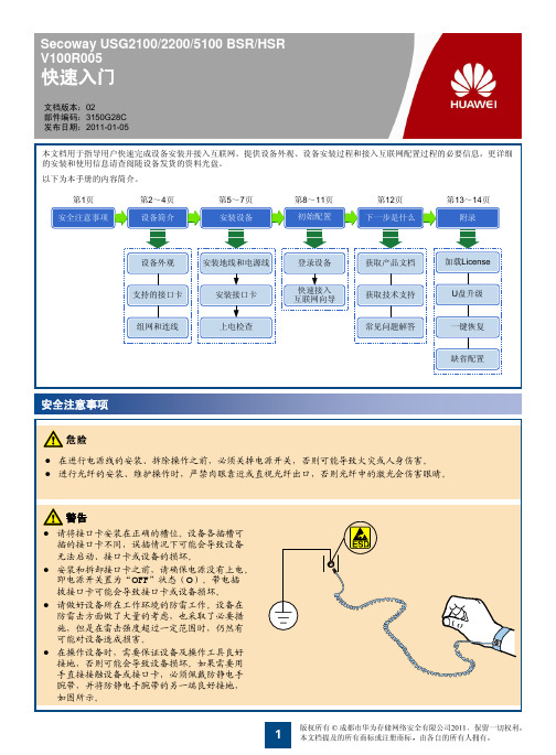
1 安装保护地线
1
1 地线一端固定到设备的接
2
地端子上。对于1U设
备,请使用M4 OT端子
(两端中较小的)那一端。
2 地线另一端与机柜 或工作台上的接地 端子相连。对于1U 设备,请使用M6 OT端子(两端中较
大的)那一端。
z 上图以USG2220 BSR/HSR为例说明,其他型号的安装 方法与此相同。
USG5150BSR/HSR
• 3U高度硬件平台,前面板上的两个电源槽位可同时安装两个交流电源模块或两个直流电源模块,实现电源模块的热备份。 • 请注意:直流电源插座左侧为RTN(+)端子,右侧为NEG(-)端子。与其它型号的直流机型相反。 • 当在FIC5、FIC6、FIC7、FIC8槽位在下半部分安装FIC接口卡时,为了防尘需要在DFIC槽位的上半部分安装一个假面板,以封闭后面板。
命令行方式
1. 连接配置线缆。将配置线缆的RJ45连接器端连接到USG的Console口上,DB9连接器端连接到PC的串口上。
配置口线缆
2. 在PC上使用串口工具登录设备。以Windows XP操作系统的超级终端为例: 1 在配置终端PC上选择“开始 > 程序 > 附件 > 通讯 > 超级终端”。
2
1 安装接口卡前,请佩戴防静电手腕带。如果安装的是USG2100BSR/HSR或USG2200BSR/HSR,请将防静电手腕带的接 地端插入到机柜或工作台的防静电插孔;如果安装的是USG5100BSR/HSR,请将防静电腕带的接地端插入到设备的防静 电插孔。
2
3
防静电手腕带
2 拧松后面板上假面板的螺钉,并取下假面板。安装 DMIC/DFIC接口卡时,请取下上下相邻的两块假 面板。
神行通AP快速安装手册
神行通无线AP操作说明1.外网连接POE 交换机的UPLink 口2.POE 交换机的POE 口连接AP 背面的WAN 口3.AP的LAN口连接电脑二、网关模式配置配置之前请先查看“高级设置”-“网络设置”,检查局域网地址网段,不要与上层设备网段相同(上层设备不能出现192.168.188.x 这样的IP 地址,如果有就要修改局域网IP 地址,可以修改为192.168.133.253),并确保DHCP 地址池的网段与局域网网段相同(即红色框中的数字相同)一、AP 网线连接网关模式可以将有线网络转换为无线网络,并提供DHCP 服务。
在这种模式下,入墙式AP 起到的功能和一台普通的路由器是一样的。
配置如下:选择自己使用的广域网类型,如果是PPPOE(ADSL)拨号用户,要填写电信提供商提供的用户名和密码,设置SSID 号(即无线网络名称)和密钥,选择信道(无线信号传输频率),然后点击“应用”,设备自动重启之后就生效了。
三、万能中继模式配置之前请先查看“高级设置”-“网络设置”,检查局域网地址,不要与网络中其它设备相同,如果有相同的IP 地址就要修改局域网IP 地址(例如192.168.188.201,192.168.188.202,192.168.188.203),并确保DHCP 地址池的网段与局域网网段相同(即红色框中的数字相同)万能中继模式可以接收无线网络信号并发射一个新的网络信号,从而实现信号的中继和放大。
此模式不提供DHCP 服务。
点击“刷新”,选择无线网,点击“选择AP”填写想要中继的无线网络的密码。
输入当前设备的SSID 号(无线选择万能中继,点击“搜索网络”网络名称)和密码,选择信道(无线信号频率),点击“应用”,设备自动重启后生效。
四、AP 模式配置之前请先查看“高级设置”-“网络设置”,检查局域网地址,不要与网络中其它设备相同,如果有相同的IP 地址就要修改局域网IP 地址(例如192.168.188.201,192.168.188.202,192.168.188.203),并确保DHCP 地址池的网段与局域网网段相同(即红色框中的数字相同)AP 模式可以将有线网络转换为无线信号,此时入墙式AP 不提供DHCP 服务,上层需要接一个路由器。
TL-SG108E 快速安装指南说明书
Installation Guide7106508554 REV5.0.0Running at 1000 MbpsTransmitting/receiving data ellow)On: Running at 10/100 MbpsFlashing: Transmitting/receiving dataLED ExplanationPowerOn: Power on Off: Power offLink/ActNote: For simplicity, we will take TL-SG108E for example throughout this Guide.Double click the icon on the desktop, and the 5/8/16-Port Gigabit Easy Smart SwitchFrequently Asked Questions (FAQ)Q1. Why is t he Power LED not lit?By default, the Power LED should be lit when the power system is working normally. If the Power LED is not lit, please try the following:A1: Make sure the power adapter is connected to the switch with power sourceproperly.A2: Make sure the voltage of the power supply meets the requirements of the inputvoltage of the switch.A3: Make sure the power source is ON.A4: (For TL-SG105E and TL-SG108E) On the LED On/Off configuration page,check whether the LED status is on. By default, the LED status is on.Q2. Why is the Link/Act LED not lit while a device isconnected to the corresponding port?Please try the following:A1: Make sure that the cable connectors are firmly plugged into the switch and thedevice.A2: Make sure the connected device is turned on and works normally. A3: The cable must be less than 100 meters long (328 feet).A4: (For TL-SG105E and TL-SG108E) On the LED On/Off configuration page,check whether the LED status is on. By default, the LED status is on.Some models featured in this guide may be unavailable in your country or region. For local sales information, visit https://.Environmental and Physical SpecificationsOperating T emperature Storage T emperature Operating Humidity Storage Humidity0 ˚C to 40 ˚C (32 ˚F to 104 ˚F)-40 ˚C to 70 ˚C (-40 ˚F to 158 ˚F)10% RH to 90% RH non-condensing 5% RH to 90% RH non-condensingSpecificationsGeneral SpecificationsStandard ProtocolInterface LED indicators Transfer Method IEEE802.3i, IEEE802.3u, IEEE802.3ab, IEEE802.3x, IEEE802.1p, IEEE802.1q CSMA/CD Ethernet:10 Mbps (Half Duplex), 20 Mbps (Full Duplex)Fast Ethernet:100 Mbps (Half Duplex), 200 Mbps (Full Duplex)Gigabit Ethernet: 2000 Mbps (Full Duplex)10Base-T:UTP category 3, 4, 5 cable (maximum 100 m)EIA/TIA-568 100 Ω STP (maximum 100 m)100Base-TX:UTP category 5, 5e cable (maximum 100 m)EIA/TIA-568 100 Ω STP (maximum 100 m)1000Base-T:UTP category 5e cable (maximum 100 m)EIA/TIA-568 100 Ω STP (maximum 100 m)5/8/16 10/100/1000 Mbps Auto-Negotiation RJ45 PortsPower, 10/100 Mbps LED, 1000 Mbps LEDStore-and-ForwardAutomatically learning, automatically aging 10Base-T: 14881 pps/Port100Base-TX: 148810 pps/Port 1000Base-T: 1488095 pps/PortY esTL-SG105E: 52 mm TL-SG108E: 110 mm TL-SG116E: 200 mmMAC Address LearningFrame Forward RateData Transfer RateNetwork Media (Cable)Wall Mountable Distance Between Mounting HolesFor technical support, the user guide and other information, please visit https:///support , or simply scan the QR code. If you have any suggestions or needs on the product guides, welcome to email **********************.cn .T o ask questions, find answers, and communicate with TP-Link users or engineers, please visithttps:// to join TP-Link Community.。
UTM快速安全手册
冠群金辰KFW-U100快速安装手册默认出厂管理地址192.168.1.99绑定在INTERNAL首次配置,使用笔记本,连接INTERNAL上的任意接口,通过https://192.168.1.99登陆系统。
出厂默认用户名:admin 密码为空一、配置UTM为透明模式进入界面后,在“系统信息”中,将NAT模式改为透明模式,点击NAT后面的[更改]选择”透明模式“填写正确的管理地址和网关地址,如下图点击”确认“后,管理地址将变为更改后的地址,如上图,变为10.75.24.253,将笔记本配置一个同网段IP,如10.75.24.252,使用https://10.75.24.253登陆设备重新。
此时,设备已经变更为透明模式。
二、接口管理访问配置进入网络=>接口,双击”internal“进入接口配置管理访问允许HTTPS PING SSH TELNET,修改后,点击”确认“。
三、修改管理员密码进入”管理员设置=>管理员“,双击admin管理员条目点击”Change Password“,修改管理员密码为:xny2013utm 点击”确认“返回四、添加访问控制策略进入”策略=>策略“,点击”创建新的“,添加两条策略,每条策略都要勾选UTM,在展开的列表中将”启用病毒检测“勾选。
第一条点确定,生成策略第二条点确定,生成策略五、日志服务器配置进入”日志与报告=>日志配置=>日志设置“,勾选”syslog服务器设置“,填写日志服务器IP:10.74.200.251,点应用。
六、修改设备系统时间点击“系统日期”后面的[更改]选择(GMT+8:00)Beijing,chongQing,HongKong,Urumgi点击“确定”完成。
七、设备上架UTM设备未透明接入方式,WAN1接外联设备,INTERNAL接口接内网交换机,如下图八、测试使用内部终端PC,ping 10.74.201.1。
UBT 5G线路接入点设备 AF-5G30-S45 快速启用指南说明书
https:///qsg/AF-5G30-S45/AF-5G30-S45_EN.html
15/21
18.02.2020
Cl ck for
×
Table of Contents
AF-5G30-S45 Qu ck Start Gu de
AF-5G30-S45 Qu ck Start Gu de
https:///qsg/AF-5G30-S45/AF-5G30-S45_EN.html
10/21
18.02.2020
Cl ck for
×
Table of Contents
AF-5G30-S45 Qu ck Start Gu de
AF-5G30-S45 Qu ck Start Gu de
Hardware Installat on
Important: Handle the D sh Re ector w th care. Deformat ons n ts shape may reduce the antenna’s effect veness.
1.
https:///qsg/AF-5G30-S45/AF-5G30-S45_EN.html
Hex Head Bolts (Qty. 5)
1/21
18.02.2020
AF-5G30-S45 Qu ck Start Gu de
AF-5G30-S45 Qu ck Start Gu de
Cl ck for
×
Table of Contents
Lock Washers (Qty. 5)
Flat Washers (Qty. 5)
20.
https:///qsg/AF-5G30-S45/AF-5G30-S45_EN.html
- 1、下载文档前请自行甄别文档内容的完整性,平台不提供额外的编辑、内容补充、找答案等附加服务。
- 2、"仅部分预览"的文档,不可在线预览部分如存在完整性等问题,可反馈申请退款(可完整预览的文档不适用该条件!)。
- 3、如文档侵犯您的权益,请联系客服反馈,我们会尽快为您处理(人工客服工作时间:9:00-18:30)。
U-SYS IAD108 综合接入设备 快速安装指南 声明 Copyright ©2004 华为技术有限公司 版权所有,保留一切权利。 非经本公司书面许可,任何单位和个人不得擅自摘抄、复制本书内容的部分或全部,并不得以任何形式传播。
®、HUAWEI®、华为®、C&C08®、EAST8000®、HONET®、®、
视点®、ViewPoint®、INtess®、ETS®、DMC®、TELLIN®、InfoLink®、Netkey®、
Quidway®、SYNLOCK®、Radium®、雷霆®、M900/M1800®、
TELESIGHT®、Quidview®、Musa®、视点通®、Airbridge®、Tellwin®、
Inmedia®、VRP®、DOPRA®、iTELLIN®、HUAWEI OptiX®、C&C08 iNET®、
NETENGINE™、OptiX™、iSite™、U-SYS™、iMUSE™、OpenEye™、Lansway™、SmartAX™、边际网™、infoX™、TopEng™均为华为技术有限公司的商标。 对于本手册中出现的其它商标,由各自的所有人拥有。
由于产品版本升级或其它原因,本手册内容会不定期进行更新。除非另有约定,本手册仅作为使用指导,本手册中的所有陈述、信息和建议不构成任何明示或暗示的担保。 i
目 录 第1章 概 述.......................................................................................1 1.1 产品简介................................................................................1 1.2 业务功能................................................................................1 1.3 系统结构................................................................................2 1.3.1 产品类型.....................................................................2 1.3.2 前面板.........................................................................3 1.3.3 后面板.........................................................................3 1.3.4 对外接口.....................................................................4 第2章 设备安装..................................................................................5 2.1 物品清单................................................................................5 2.2 安装注意事项.........................................................................5 2.3 硬件安装................................................................................6 2.3.1 放置设备于工作台.......................................................6 2.3.2 连接上行电缆..............................................................6 2.3.3 连接用户侧电缆..........................................................8 2.3.4 连接电源线..................................................................8 2.3.5 连接串口电缆..............................................................9 第3章 故障诊断与排除.....................................................................11 1
第1章 概 述 本章从产品定位、功能特点、系统结构和技术规格角度介绍了U-SYS IAD(Integrated Access Device)108综合接入设备的概况(下文简称IAD108)。
1.1 产品简介 IAD108作为华为技术有限公司下一代网络NGN(Next Generation Network,下文简称NGN)产品系列化解决方案的重要部件,可提供基于IP网络的高效、高质话音服务,为企业、小区、公司等提供小容量VoIP(Voice over IP)/FoIP(Fax over IP)解决方案。 IAD108是基于IP语音VoIP/传真FoIP的媒体接入网关,可通过模拟电话、传真机等普通设备,将传统PSTN(Public Switched Telephone Network)用户接入到IP网络,产品外观如图1-1所示。
图1-1 IAD108产品外观图 1.2 业务功能 IAD108可向用户提供丰富的语音、数据业务,如下所示: l 将POTS(Plain Old Telephone Service)用户接入到IP分组网络;
l 将以太网用户接入到IP分组网络; 2
l 支持IP半永久连接和内部半永久连接; l 支持T.38传真或传真的透明传输; l 支持Modem透明传输;
l 提供用户线测试(可选); l 支持ADSL、VDSL上行;
l 支持环境监控;
l 支持时钟功能; l 支持远程供电功能;
l 支持下行口防雷; l 支持传统PSTN电话业务,如呼叫转移、主叫号码显示、呼叫等待等,且在用户话机支持下可为用户提供留言灯功能; l 配合SoftSwitch,可实现新国标中规定的各种新业务;
l 配合SoftSwitch,可实现智能业务和特色应用业务。
& 说明: ADSL/VDSL上行、环境监控、时钟、远程供电、下行口防雷仅豪华版IAD108支持,标准版IAD108不提供。
1.3 系统结构 1.3.1 产品类型 IAD108最大支持8路POTS用户的IP语音接入,并提供2个10/100Base-T的下行网口和1个上行网口。 上行网口由上行接口板提供,上行接口板有3种类型,因此IAD108按上行接口类型可以被分为表1-1所示的三种。 3
表1-1 按上行接口类型划分的IAD108类型 项目 说明 IAD108A(T) 提供ADSL(Asymmetric Digital Subscriber Line)上行口。 IAD108E(T) 提供FE(Fast Ethernet)上行口。
IAD108V(T) 提供VDSL(Very High Speed Digital Subscriber Line)上行口。
在IAD108的机盒前面板、上面板及左右两边都设有通风口,利于设备的散热。
1.3.2 前面板 IAD108前面板设有指示灯,各灯名称及含义如表1-2所示。 表1-2 IAD108前面板指示灯含义说明 指示灯 颜色 名称 含义
PWR 绿色 电源指示灯 接本地电源时常亮,无电源时灭。 接远供电源时闪烁,无电源时灭。
RUN 绿色 运行指示灯 上电加载时快闪(0.125秒亮,0.125秒灭)。 正常运行时慢闪 (1秒亮、1秒灭)。 向SoftSwitch注册失败(0.5秒亮,0.5秒灭)。
WAN 绿色 上行接口指示灯 上行接口正常时亮,不插网线时灭。
1~8 绿色 电话用户指示灯 相应端口的用户摘机时亮,挂机时灭,振铃时闪烁。
1.3.3 后面板 IAD108后面板分布了所有对外接口,如图1-2所示。 4
(1):本地电源插口 (2):上行接口 (3)、(4):数据用户接口。 (5)~(12):POTS接口 (13):本地维护串口
图1-2 IAD108对外接口示意图
1.3.4 对外接口 表1-3 IAD108对外接口列表 项目 说明 RJ11型POTS接口 提供8路。 RJ-45型10M/100Base-TX用户接口 提供2路。 IAD108A(T)提供1路ADSL。 IAD108E(T)提供1路FE。 RJ-45型上行接口 IAD108V(T)提供1路VDSL。 RS232本地维护串口(Console) 提供1路。