德国burkert127型手册
burkert-1067-定位器

等待30— 120秒
THANK YOU!!!
• 让我们互相学习,构建美好未来!!
如果气源消失,阀门依靠弹簧复位
外部反馈/位置传 感器(上下动作)
Wet 破真空阀
电缆插座
外部反馈/位置传 感器 信号线
安装板
O型圈
1067定位器
执行器进气口
和定位器出气口 相连
阀门开度值由 PLC 4—20MA模 拟量信号给入
WET 真空混料破真空阀
执行器阀杆 外部反馈/位置传感器的滑块在上下滑动过程中松动\脱落 造成阀门 定位错误 产生报警
Positioner 1067 交流稿
手动/自动
电源 : 24VDC 气压0—6bar 1067 定位器分为两种 1:内部反馈/位置传感器 采用旋转电位计
2: 外部反馈/位置传感器 采用外部线性电位器 按5秒手动/自动 键进入 组态界面
Wet 真空混料 破真空阀
单作用
名词解释 单作用:气缸的移动通过仪表空气的压力,返回时由弹簧提供压力
Nucon 大料罐 放料阀
阀门 和执行 器连接处
内部反馈/位置传 感器 (转动)
双作用
名词解释
双作用:气缸的移动和返回都是通过仪表空气来提供动力。 单作用的扭矩要比双 作用的小得多。故双作用一般用于需要较大扭矩的阀门.如果两边气源同时切断 阀门将保持断气前的开度
定位器的主菜单项
• X-SENS
选择 direct
信号常开常闭输出 设定
阀门开度大于设 定值 输出信号
例如 :值设定为5 阀门关闭度大于 等于5信号输出 , 触发相关的程序 连锁,小于5不输
出
自动校正
பைடு நூலகம்
二战德军作战手册
前言由于其火力,防护和机动力,坦克团是陆军师中最重要的战斗单位。
它的打击能力在于出其不意的,集中火力的坚定的进攻;以及富于进取精神的指挥和大胆的行动。
序在俄国的战斗再一次表明,在与共产主义者的作战中,决定的因素是装甲兵的精神与技能,而不是坦克的数量和种类。
长久以来,正是由于我军在这方面的优势使得德国坦克部队所向无敌,即便在俄国也是如此。
然而,在平庸的指挥官手下,模范的战斗素质有时并不如武器的数量、装甲和速度来的有效。
高人一筹的战术指挥是减少或消除伤亡的前提。
本文的目的是汇编前线老兵的经验,并言简意赅地传授给新进下级军官们。
正文一、熟悉战区。
积极掌握友邻部队和地图提供的信息,并及时与部下分享。
准确的情报和谨慎的估计是区分胜利与失败的决定因素。
二、欲速则不达。
即便在最紧要的关头也要使部下清楚地掌握情况和计划。
轻率冒进可能把胜利变成悲剧,指挥官要对任何由此带来的损失负责。
三、眼观六路。
细致的侦察警戒是安全的第一保障,保持对各个方向的观察是指挥官的职责。
要象对正面一样地对待侧翼,时刻瞪大眼镜准备敌人的到来。
四、不要摇摆不定。
指挥官的能力首先体现在持续贯彻一个清晰的意图。
只有这样,你才能在千钧一发的时刻迅速给出正确清晰的命令。
指挥官的领导责任正在于此。
五、无线通讯纪律要严格。
这是成功指挥的先决条件,尤其在无线电是唯一通讯手段的时候。
比如在尖刀连中,后卫排在除紧急情况外应该保持无线电静默,将信道留给尖刀排。
六、火力要集中。
前锋至少要有两辆坦克,后卫排要保持与前锋排的距离以提供火力支援。
在第一时刻开火的主炮越多,敌人瓦解得越快,你的损失也越小。
七、伏击要坚决。
跃起时要迅速、同步。
突然出现在敌人面前的火力越多,敌人的控制和指挥越困难,你的火力优势越大。
八、进攻中坦克行驶速度要快。
在低速情况下,观察和射击只会有微小的提高,而被击中的危险则大大增加。
坦克只应该有两个速度,半速(射击时!)和全速前进。
这是坦克作战的基本原则!九、在中远距离遭遇敌反坦克火力时,应首先向其开火,然后再作机动。
潮尔氏控制设备类型1271一级单阶操作手册说明书

TYPES2012511271Operating CharacteristicsWhen the float rises to the operating point, the switch or switch-es are actuated by the mutual attraction between a magnetic plunger attached to the float within the float chamber and a mag-net attached to the switch operating assembly. When the float drops, the magnetic plunger is moved out of the field of the mag-net on the switch operating assembly and the switch or switches are restored to their original position by gravity.The magnetic plunger attached to the float moves within a tube within the switch enclosure. The switch unit is mounted on the tube singly or in pairs. Type 1271 - Single Stage Only. Explanation of Type and Code NumbersExample: Type 201G-4820-C1-60.201 is the type number of the control; letter “G” denotes enclo-sure; -4820 designates circuit arrangement; C1 denotes materials of construction; 60 indicates pressure rating and specific gravity. EnclosuresGeneral Purpose enclosures are identified by the letter ‘G: in type number as in 201G, 1273G.Weather Resistant enclosures are identified by the letter “W” in type number as in 204W, 211W.Explosion-proof enclosures are identified by the letter”E” in type number as in 201E, 1274E.Explosion-proof -- Vapor-proofletters “EV” in type number as in 203EVSpecial FeaturesSemi-Automatic(with manual reset) operates automatically onBulletin O-421C Page 2“A” - level at which single (or lower stage) operates on level rise.“B” - operating differential single (or lower stage) - drop in level to restore switch to original position.“C” - level at which upper stage operates on level rise.“D” - operating differential of upper stage - drop in level to restore switch to original position.“E” - increase in level above “A” to operate upper stage.Illustration No. 10Illustration No. 11LIQUID LEVEL CHANGES IN INCHES OF WATER FOR-Series 201, 203, 204, 221, 223, 224, 251, 253, 254Minimum Specific Gravity 0.75Single Stage OperationSpecific Gravity 1.0 & .75 -“A” is Adj. ±1˝Single Stage with WideDifferential “A” Not AdjustableSp. Gr.1.0.75“A”7-1/4˝8˝“B”3/4˝1˝Code C1-75Sp. Gr.1.0.75“A”8˝8-3/4˝“B”2˝2˝Code C1-75(See Illustration No. 10)Two Stage Operation“A”- Not Adjustable Sp. Gr.1.0.75“A”6-1/4˝7˝“B”3/4˝1˝“C”8-1/2˝9-1/2˝“D”1-1/4˝1-3/4˝“E”2-1/4˝2-1/2˝Code C1-75See Illustration No. 10LIQUID LEVEL CHANGES IN INCHES FOR SWITCH OPERATIONSeries 211, 213, 214, Minimum Specific Gravity 0.6450 PSI at 100°F , or 300 PSI at 500°F .Single Stage Operation“A” is Adj. ±1”Single Stage with Wide Differential “A” Not Adjustable Sp. Gr.1.0.6“A”6-3/4˝8˝“B”3/4˝1-1/4˝Sp. Gr.1.0.6“A”7-1/2˝8-3/4˝“B”1-3/4˝2˝“A” - level at which single (or lower stage) operates on level rise.“B” - operating differential single (or lower stage) - drop in level to restore switch to original position.“C” - level at which upper stage operates on level rise.“D” - operating differential of upper stage - drop in level to restore switch to original position.“E” - increase in level above “A” to operate upper stage.Two Stage Operation“A”- Not Adjustable Sp. Gr.1.0.6“A”5-3/4˝7˝“B”3/4˝1-1/4˝“C”8˝9-1/2˝“D”1-1/4˝2˝“E”2-1/2˝2-1/4˝LIQUID LEVEL CHANGES IN INCHES OF WATER FOR - Series 1271,1273, 1274 - Minimum Specific Gravity 0.58Single Stage Only “A” Not AdjustableSp. Gr.1.0.58“A”6-11/16˝8-1/4˝“B”1˝2˝FOR SERVICE OTHER THAN SATURATED STEAMCONSULT FACTORYType201251Minimum Specific Gravity 0.60.750.75100°F 600 psi 1000 psi 1250 psi and 650°F750°F Max.500 psi 750 psi 750 psiCode C1-60C1-75C1-75PRESSURE RATINGS Series 201, 251One horizontal and one vertical 1˝ NPT pipe connection.Pressure Rating AtFLANGE AND FLOAT SPECIFICATIONSSeries 203, 253: (1) one vertical and (1) horizontal flanged connec-tion (1˝ FR forged steel - ANSI specifications.)Series 204, 254: Two vertical flanged connection (1˝ RF forgedsteel - ANSI specifications).Type 203204253254Minimum SpecificGravity 0.60.750.75100°F 275 psi 600 psi 600 psi 275 psi 720 psi 1000 psi 1250 psi and 650°F750°F Max.100 psi 425 psi 500 psi 100 psi 425 psi 750 psi 750 psi Code C1-160C1-360C1-660C1-175C1-375C1-675C1-675Pressure Rating At Flange Class PSI 150300 600150300600600Types 211,(1) vertical and (1) horizontal 1˝ NPT pipe connection Type 213,(1) flange vertical and (1) flange horizontal 1˝ RF forged steel.Type 214,Both flanges vertical 1˝ RF forged steel.Type 211213214Minimum SpecificGravity 0.60.6100°F 450 psi 275 psi 450 psi 450 psi 500°F Max.300 psi 150 psi 300 psi 300 psiCode C1-60C1-160C1-360C1-660Pressure Rating At FlangeClass PSI ---150300600"D""E""B""A""C"CLAMP SCREWFLOAT RODFLOAT3/4 NPT COND CONN ROT AT ABLE TO 360°MERCURY SWITCHASSEMBL YARMATURE TUBE"C""E""B""D""A"FLANGE AND FLOAT SPECIFICATIONSSeries 221, 223, 224One vertical and one horizontal 1˝ NPT pipe connection. Type 221:(1) vertical and (1) horizontal 1˝ NPT pipe connection. Type 223:(1) flange vertical and (1) flange horizontal 1˝ RF forged steel.Type 224:Both flanges vertical 1˝ RF forged steel.Type 221 223 224MinimumSpecificGravity0.60.750.60.75100°F600 psi1000 psi600 psi600 psi275 psi720 psi1000 psi475°F Max.550 psi850 psi550 psi550 psi150 psi625 psi850 psiCodeC1-60C1-75C1-360C1-660C1-175C1-375C1-675 Pressure Rating AtFlangeClass PSI------300600150300600Type 1271:(1) vertical and (1) horizontal 1˝ socket weld pipe con-nection.Type 1273:(1) flange vertical and (1) flange horizontal 1˝ RF forged steel.Type 1274:Both flanges vertical 1˝ RF forged steel.Type 1271 1273 1274MinimumSpecificGravity0.580.580.580.580.58660°F2325 psi1520 psi2325 psi1520 psi2325 psiCodeC1-58C1-958C1-1558C1-958C1-1558Pressure Rating AtFlangeClass PSI---90015009001500CIRCUIT ARRANGEMENTSControls with Mercury SwitchesSingle Stage Only120/240 V-4820-4821-4815-4814-4813Specification No.440 V-5820-5821-5815-5814-5813CircuitArrangementSP-STSP-STSP-DTDP-STDP-STCircuit Responseto Liquid LevelChangesCloses As Level FallsCloses As Level RisesOne Circuit Closes AsOther Circuit OpensCloses As Level FallsCloses As Level RisesTwo-Stage Operation(With Mercury Switches). Any two circuits shownin circuit arrangement table are available on each stage for 120/240 volts.Example: -4820-13 designates a SP-ST lower stage to close as level fallsand a DP-ST upper stage opens as level falls.Circuit ArrangementsWith Snap-Acting SwitchesSingle StageSpecification No. -7810 (1) SP-DT SwitchSpecification No. -7806 (2) SP-DT SwitchesTwo StageSpecification No. -7810-10 SP-DT Each Stage.Specification No. -7806-06 DP-DT Each Stage.Do not oil any parts. Never leave cover off the switch operatingmechanism. Do not tamper with switch wires. Position of thesewires is essential to proper operation. Tampering with these wireswill void warranty.©Copyright 2003Dwyer Instruments, Inc.Printed in U.S.A. 1/03FR# 97-441673-00 Rev.1MERCOID DIVISIONDWYER INSTRUMENTS, INC.P.O. BOX 258 • MICHIGAN CITY, INDIANA 46361 U.S.A.Phone: 219/Fax: 219/872-9057e-mail: info@ Lit-by-Fax: 888/891-4963。
博世博科6527型5 2路电磁阀手册说明书

5/2-way Solenoid Valve for pneumaticsThe solenoid valve Type 6527 consists of a pneumatic valve body fi tted with Type 6106 rocker pilot valve. The rocker principle allows switching of high pressures together with low power consumption and fast response times. The extendable Type 6527 can be used for block modules (tag connectors in front) or for entire valve islands (8640 & 8644 - tag con-nectors at the block).All valves are equipped with manual override as a standard.Type 2506Cable plugType 2510/2511ASI cable plugType 8640Valve islandType 2031Diaphragm valveType 8644Valve islandType 0044Pneumatic cylinderOrdering chart for valves5/2-way solenoid valve without cable plug1)2) Electrical connection above manual ride.3) In combination with valve islands the closing time will be approx. 5ms longer.Flow rate, QNn-value air [l/min]: Measured at +20ºC, 6 bar pressure at value inlet and 1 bar pressure differencePressure values [bar]: Measured as overpressure to the atmospheric pressureResponse times [ms]: Measures acc. to ISO 12238Please note that the cable plug has to be ordered separately, see ordering chart for accessories on last page or separate datasheet for Type 2506. Ordering chart for accessories: Type MP12 pneumatic modulesDimensions [mm]Application example14 Actuators (process valves, cylinder) are controlled 8 double acting actuators (large volume)6 double acting actuators (small volume)To fi nd your nearest Bürkert facility, click on the orange box ‡In case of special application conditions,please consult for advice.We reserve the right to make technical changes without notice.0710/2_EU-en_00891916Sectional drawingOrdering chart for accessories pneumatic modules Type MP12The delivery of a socket connection includes the fl at seal and the mounting screw. For other socket connection models with integrated circuitry to DIN EN 175301-803 (previously DIN 43650) Form C, see datasheet 2506.。
LD127说明书
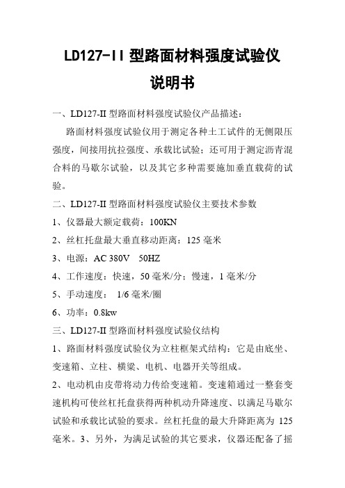
LD127-II型路面材料强度试验仪说明书一、LD127-II型路面材料强度试验仪产品描述:路面材料强度试验仪用于测定各种土工试件的无侧限压强度,间接用抗拉强度、承载比试验;还可用于测定沥青混合料的马歇尔试验,以及其它多种需要施加垂直载荷的试验。
二、LD127-II型路面材料强度试验仪主要技术参数1、仪器最大额定载荷:100KN2、丝杠托盘最大垂直移动距离:125毫米3、电源:AC 380V 50HZ4、工作速度:快速,50毫米/分;慢速,1毫米/分5、手动速度:1/6毫米/圈6、功率:0.8kw三、LD127-II型路面材料强度试验仪结构1、路面材料强度试验仪为立柱框架式结构:它是由底坐、变速箱、立柱、横粱、电机、电器开关等组成。
2、电动机由皮带将动力传给变速箱。
变速箱通过一整套变速机构可使丝杠托盘获得两种机动升降速度、以满足马歇尔试验和承载比试验的要求。
丝杠托盘的最大升降距离为125毫米。
3、另外,为满足试验的其它要求,仪器还配备了摇把,用摇动丝杠托盘升降移动,横梁上装有一个固定螺钉孔、可将适当的测力环螺栓固定在横梁上供试验使用。
4、电器开关可控制电机的正转(上升),反转(下降)和停止。
四、LD127-II型路面材料强度试验仪操作规程1、通电源检查相位是否正常,上升按扭起动后必需上升,方可使用。
2、根据试验具体要求,选择速率手柄,手柄有3个选择位置,(以手柄上刻线与标盘为准),将选择手柄置于50mm/min 位置,旋动开关,可使托盘获得每分钟50毫米的升降速度,适宜于做沥青混合料的马歇尔试验。
3、将手柄选择置于1mm/min的位置,旋动开关,可使托盘获得每分钟1毫米的升降速度,适宜做承载比(CBR)等试验。
4、将手柄选择置于0的位置,可用摇动可获得1/6毫米圈的速度。
5、进行试验时,先将测力环用螺栓固定在横梁上,在将适当的附件(压头)固定在测力环下,将试件置于丝杠托盘中间,然后进行试验,试验所施加的载荷量,可以从测力环百分表上读出,(百分表指针回转时)。
H127资料
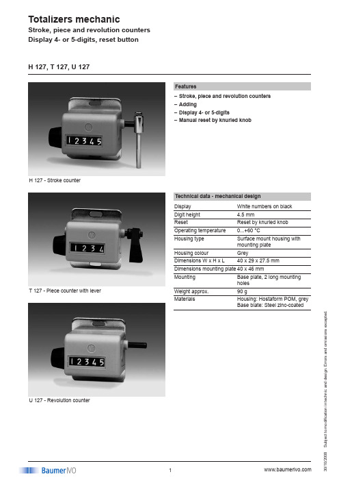
S u b j e c t t o m o d i fi c a t i o n i n t e c h n i c a n d d e s i g n . E r r o r s a n d o m i s s i o ns ex c e p t e d .008H 127 - Stroke counterFeaturesStroke, piece and revolution counters –Adding–Display 4- or 5-digits–Manual reset by knurled knob–H 127, T 127, U 127Technical data - mechanical design Display White numbers on black Digit height 4.5 mmResetReset by knurled knob Operating temperature 0...+60 °CHousing type Surface mount housing with mounting plate Housing colour GreyDimensions W x H x L 40 x 29 x 27.5 mmDimensions mounting plate 40 x 46 mmMountingBase plate, 2 long mounting holes Weight approx.90 gMaterialsHousing: Hostaform POM, grey Base blate: Steel zinc-coatedT 127 - Piece counter with leverU 127 - Revolution counterS u b j e c t t o m o d i fi c a t i o n i n t e c h n i c a n d d e s i g n . E r r o r s a n d o m i s s i o n s e x c e p t e d .008H 127, T 127, U 127Drive on the rightReset button left Reset button left Away from userToward userSense of rotation or Sense of rotation or stroke direction Istroke direction IIDrive on the leftReset button right Reset button right way from user Toward user Sense of rotation or Sense of rotation or stroke direction I stroke direction IIReset button always opposite of drive.Direction of strokes and rotation Technical data - mechanical design H 127Function Stroke counter Number of digits 5-digitsCount mode Adding in a stroke direction to be indicated. 1 stroke = 1 count Drive shaft Right or left, ø4 mm Stroke >38° to <60°Stroke leverTo be positioned on shaft at will. Stroke lever relocates automatically to start position.Stroke frequency ≤500 strokes/min Measuring range 99 999T 127Function Piece counter with lever Number of digits 4-digitsCount mode 1 button touch = 1 count Drive shaft Only available with lever provided at right Stroke>38° to <60°Measuring range 9999U 127Function Revolution counter Number of digits 5-digitsCount modeAdding in a rotational direction to be indicated, subtracting in reverse direction. 1 rev. = 1 countDrive shaft Right or left, ø4 mm Operating speed ≤2000 rpm Measuring range99 999S u b j e c t t o m o d i fi c a t i o n i n t e c h n i c a n d d e s i g n . E r r o r s a n d o m i s s i o n s e x c e p t e d .008H 127, T 127, U 127Part number H 127.0ADisplay / direction of strokeG 5-digits 99 999 / I H 5-digits 99 999 / IICount mode / drive01 1 stroke = 1 digit / drive shaftat right02 1 stroke = 1 digit / drive shaftat leftHousingA Surface mount housing, greyReset1Reset button at left2Reset button at rightT 127.001Design001Display 4-digits, stroke direction II,Reset button left, 1 stroke = 1 digit Housing grey, surface mountU 127.0ADisplay / direction of rotationG 5-digits 99 999 / I H 5-digits 99 999 / IICount mode / drive01 1 revolution = 1 digit / driveshaft at right02 1 revolution = 1 digit / driveshaft at leftHousingA Surface mount housing, greyReset1Reset button at left2Reset button at rightStroke counter Piece counterRevolution counterS u b j e c t t o m o d i fi c a t i o n i n t e c h n i c a n d d e s i g n . E r r o r s a n d o m i s s i o n s e x c e p t e d .008Dimensions 6047ø438466403.227.51021745°2920.310.5T 127H 127, U 127H 127, T 127, U 127。
战后厄利空小口径机关炮系列介绍
战后厄利空⼩⼝径机关炮系列介绍原先在这个帖⼦⾥讨论,https:///forum.php?mod=viewthread&tid=2422937后来发现需要修补的地⽅太多,⽼编辑回复也不是个事,所以还是决定单独开⼀个贴。
本⽂主要介绍厄利空/厄利孔(Oerlikon)在⼆战结束后相对有名的⼏款⼩⼝径机关炮。
舰炮系列有Yak-28的⼤作海军⼩⼝径机关炮⼩史(中)珠⽟在前,本⼈对舰炮也⼀知半解,因此不过多涉及。
要理清厄利空系列⾸先要明⽩其代号意义。
第⼀个字母:K第⼆个字母:表⽰⼝径,A:20mm、B:25mm、C:30mm、D:35mm。
第三个字母:该⼝径的第⼏种型号。
注意第⼆个字母仅⽤于标⽰⼝径,并不保证同⼀系列的⽕炮拥有相同技术渊源或使⽤相同弹药。
⼀、KA系列1、KAA 20mm机关炮 85倍径⾝管,使⽤20×128mm弹药。
该炮是⼆战期间闻名遐迩的厄利空 20mm/L70的后继,主要⽤于舰炮,陆战⽕炮仅知道的应⽤实例是斯洛伐克的T-72M2 莫德纳Moderna,在炮塔后部安装了两门KAA。
因为不成功,后来改⽤1门苏式2A42 30mm机关炮。
安装2门KAA的T-72M2 莫德纳2、KAB 20mm机关炮 只知道使⽤20×128mm弹药,设计⽤于陆战,平射和防空两⽤,其余信息不详。
3、KAD 20mm机关炮 使⽤20×139mm弹药。
该炮原先是西斯帕诺·絮扎(Hispano-Suiza)的HS.820机关炮,后来被厄利空收编,赋予编号KAD。
这个炮是⼀代经典,除了原版之外,美国引进⽣产赋予编号M139。
根据某海军武器⽹站的介绍,法国的M693(F2) 20mm舰炮也仿⾃该炮。
考虑到该⽹站经常把很多略有差异的武器归为同⼀类(例如我国的79式100mm/L60舰炮被归类为苏联B34 100mm/L56的同⼀⽕炮不同炮塔),这个说法姑且存疑。
同样存疑的还有德国Rh 202 20mm机关炮。
KDG-127-3-4矿用远程控制箱使用说明书061128(1)
KDG-127/3-4型矿用远程控制箱使用说明天津华宁电子有限公司目录1.概述 (2)1.1.适用范围 (2)1.2.使用环境和条件 (2)1.3.型号及其含义: (2)1.4.形式 (2)2.结构特征 (2)3.外形、尺寸及重量 (3)4.技术特性 (3)4.1.主要参数: (3)4.2.主要功能: (4)5.工作原理 (4)5.1.原理及内部配线图 (4)5.2.原理阐述 (5)6.安装及使用 (5)7.故障分析与解决 (6)8.维护和保养........................................................... 错误!未定义书签。
9.包装、运输和贮存..................................................... 错误!未定义书签。
10.订货须知............................................................ 错误!未定义书签。
为了保证安全并获得最佳效能,安装使用产品前,请详细阅读使用说明书并妥善保管,以备今后参考。
KDG-127/3-4型矿用远程控制箱说明书1. 概述 1.1. 适用范围KDG-127/3-4型矿用远程控制箱适用于煤矿井下,有煤尘及爆炸性气体的环境下,是KTC101通讯控制系统的辅助设备。
通过继电器隔离达到本安和非本安接点的转换。
也可以用到需要本安非本安转换的其他地方。
1.2. 使用环境和条件a )工作环境温度为0℃~+40℃;b )周围空气相对湿度不超过95% (+25℃);c )大气压力为80kPa ~106kPa ;d )有甲烷和煤尘等爆炸危险的矿井中;e )无破坏绝缘的腐蚀性气体的矿井中;f )无剧烈振动和冲击的地方;g )允许有溅水的环境中。
1.3. 型号及其含义:开关触点电压/电流控制开关矿用电源电控设备控制路数KD G127/34图1:型号含义图1.4. 形式1.4.1. 防爆型式:矿用隔爆兼本质安全型,标志:Exd [ib ]Ⅰ。
二战德国陆军火炮全集 5.二战德军火炮全集-野战炮
5.二战德军火炮全集-野战炮野战炮——————field gun75毫米野战炮系列75毫米 leFK 38野战炮75毫米 FK 40野战炮75毫米FK 7M 85野战炮75毫米le. FK 16野战炮75毫米le. FK 18野战炮说明:德国的75毫米野战炮系列,对于德军来说,生产这样性能不佳的野战炮得不偿失,因为其性能和德军中的轻型迫击炮和性能、作战任务雷同,但是野炮拥有更大的重量,不符合闪电战战略对火炮的要求。
,而75毫米野炮的有限的射程,同样重量很轻的迫击炮也能达到,使得德军中的75毫米野战炮的地位很尴尬。
二战中,德军主要装备两种型号的75毫米野战炮,一种是一战的老兵75毫米 le. FK 16 n.A.野炮发展的75毫米le. FK 16野战炮,另一种是二战德军发展的替代型号:75毫米 le. FK 18 野炮。
这些75毫米野炮,在德军中的地位既不突出,性能也不显著,但伴随德军走完整个二战历程。
德军75毫米 le. FK 18 野炮在二战的许多战役中多次被使用到,其射程加强型虽然增加了射程,但是重量增加,使的机动性下降。
为了寻找解决办法,异想天开的德国人开始在德军中性能优秀的标准的反坦克炮身上打主意了。
德军中性能不错的75毫米 PAK 40 反坦克炮开始进入德国火炮专家的法眼。
德国火炮专家以75毫米 PAK 40 反坦克炮为蓝本,研制出了两种改进的野炮型号,他们是:75毫米 FK 40野战炮和75毫米FK 7M 85野战炮,但是这两种野战炮投产时间太迟,以至于在战争期间没有发挥什么作用。
75毫米 le. FK 18野战炮口径: 75 毫米L/26炮架长: 5.20 米生产时间:1930年长: 1.94 米宽: 1.83 米高: 1.65 米火炮射界:左右正负55度火炮俯仰角:-4度—+45度炮弹重: 5.9 公斤最大射速: 10 发/分出膛初速度: 485 米/秒最大射程: 9 414 米人员编制:8人75毫米 le. FK 18 L / 26野战炮75毫米 le FK 38 野战炮性能参数:口径: 75 毫米 L/34炮架长: 5.60 米生产时间:1939年火炮射界:左右正负55度火炮俯仰角:-4度—+55度长: 2.55 米宽: 1.88 米高: 1.57 米最大射速: 11 发/分出膛初速度: 580米/秒最大射程: 11 300 米人员编制:8人75毫米 le. FK 38 L / 34野战炮75毫米 le. FK 38 L / 34野战炮不同炮弹穿甲能力:K.Gr.rot.Pz. ( Armor Piercing Capped Ballistic Cap =APCBC)距离:100米=500 米=1000米=1500 米=2000 米炮弹重量:6.08 公斤穿甲厚度:59毫米= 55毫米=51 毫米=47毫米=33毫米Gr.38 Hl / A ( 反坦克高爆弹 )距离:100米=500 米=1000米=1500 米=2000 米炮弹重量:4.40公斤穿甲厚度:75毫米= 75毫米=75毫米=75毫米=0说明:75毫米leFK38野战炮,性能比75毫米 le. FK 18野战炮有所提高,但是付出的代价是炮重增加。
二战德军火炮全集)
二战德军火炮全集(2)防空炮2008-05-29 14:1620毫米 Flak: global 系列:5种变型发展:20毫米 C/30 L20毫米 Flak 2820毫米 MG 151/20 Drilling20毫米 Flak 3020毫米 FlaK 3820毫米 Flak 28性能参数:口径:20毫米人员:5人出膛速度:830米/秒平射射程:4400米高射射高:3700米说明:该炮是德国一战凡尔塞条约签定已来发展的第一种高射炮,尽管设计比较原始,但是有些还是在德军中服役到1939年。
1928年,瑞士曾经购买过该炮20毫米 Flak 30 高射炮性能参数:口径: 20 毫米炮架长: 4米长: 2.30 米宽: 1.80 米高: 1.6 米射速: 120发/秒出膛速度: 900 米/秒射程: 4 800 米射高: 2 200 米说明:最初的20毫米 Flak 28,进一步发展了海军的自动高射炮20毫米 C/30 L。
20毫米 C/30 L便于修理与维护,进入海军服役是在1934年。
20毫米 Flak 30则是二战爆发德军的主要防空炮,是二战前德军防空部队的标准配置火炮。
尽管20毫米 Flak 30后来被深灰色的20毫米 Flak 38所取代,主要缺点是火力不足。
20毫米 Flak 36 高射炮性能参数:口径: 20毫米炮架长: 4.30 米长: 2.25 米宽: 2.40 米高: 2.2 米射速: 800 发/分出糖速度: 900 米/秒射程: 4 800 米射高: 2 200米装备20毫米 Flak 36 高射炮的德军Wirbelwind自行高炮20毫米 Flak 38 高射炮性能参数:口径: 20 毫米 L/112.5 (112.5为倍径)炮架长: 4.00 米长: 2.25 米宽: 1.80米高: 1.7 米射速: 220 发/分出膛速度: 900米/秒射程: 4 800 米射高: 2 200 米装备了20毫米 Flak 38 高射炮的德军Flakpanzer 38 (t) "Gepard"自行高炮20毫米 Gebirgsflak 38 高射炮:说明:主要装备德军的山地部队的连级单位,用于山地部队的防空作战。