LabVIEW(虚拟仪器(LabVIEW)) 外文翻译
虚拟仪器课程论文-LabVIEW的发展历史、研究现状及其展望

课程名称: 虚拟仪器学院: 机电工程学院专业: 仪器仪表工程姓名: 刘@学号: 4 2论文介绍:经过一学期的虚拟仪器学习,对LabVIEW的使用有了更深入的了解,有很多思维和方法在今后的学习中值得借用,在此感谢万老师的辛勤付出。
本论文主要论点:LabVIEW的发展历史、研究现状及其展望,并分析与其它平台的比较优势,本人测控专业且目前研究方向主要涉及到FPGA的应用,所以文章分析了LabVIEW与MATLAB和FPGA(现场可编程门阵列)等平台的融合,并在此基础上分析LabVIEW最新的应用实例,最后做出总结与展望。
0.引言随着计算机技术、大规模集成电路技术和通讯技术的飞速发展,仪器技术领域发生了巨人的变化,美国于1986 年首先提出基于计算机技术的虚拟仪器(Virtual lnstruments 简称Ⅵ)的概念,把虚拟测试技术带入新的发展时期,随后研制和推出了基于多种总线系统的虚拟仪器。
虚拟仪器就是在通用计算机上加上软件和硬件,使得使用者在操作这台计算机时,就好象在操作一台自己设计的专用的传统电子仪器。
它可代替传统的测量仪器,如示波器、逻辑分析仪、信号发生器、频谱分析仪等;可集成于自动控制、工业控制系统;可自由构建成专有仪器系统。
它由计算机、应用软件和仪器硬件组成。
无论哪种虚拟仪器系统, 都是将仪器硬件搭载到笔记本电脑、台式PC或工作站等各种计算机平台(甚至可以是掌上电脑) 上,加上应用软件而构成的[1]。
虚拟仪器通过软件将计算机硬件资源与仪器硬件有机的融合为一体,从而把计算机强大的计算处理能力和仪器硬件的测量、控制能力结合在一起,大大缩小了仪器硬件的成本和体积,并通过软件实现对数据的显示、存储以及分析处理。
1.虚拟仪器发展历史及现状LabVIEW( Laboratory Virtual Instrument Engineering Work bench,实验室虚拟仪器工程平台) 是由美国NI公司( National Instruments ,国家仪器公司) 创立的一个功能强大而又灵活的仪器和分析软件应用开发工具,在实验测量、工业自动化和数据分析领域有着重要作用。
LabVIEW软件介绍及编程实例
功能模板
测量子模板:包括数据采集硬件的驱动程序, NI 测量子模板:包括数据采集硬件的驱动程序,以及信 号调理所需的各种功能模块。 号调理所需的各种功能模块。 波形子模板:包含了对各种波形的控制。 波形子模板:包含了对各种波形的控制。 分析子模板:包括信号发生、时域及频域分析功能模块。 分析子模板:包括信号发生、时域及频域分析功能模块。 仪器控制子模板:包括GPIB(488 488.2)、串行、VXI仪 GPIB(488、 仪器控制子模板:包括GPIB(488、488.2)、串行、VXI仪 器控制的程序和函数,以及VISA的操作功能函数。 VISA的操作功能函数 器控制的程序和函数,以及VISA的操作功能函数。 应用程序控制子模块:包括动态调用VI VI、 应用程序控制子模块:包括动态调用VI、标准可执行程序 的功能函数。 的功能函数。 图形与声音子模块:包括3 OpenGL、 图形与声音子模块:包括3D、OpenGL、声音播放等功能 模块。 模块。 通讯子模板:包括TCP DDE、ActiveX和OLE等功能的处理 TCP、 通讯子模板:包括TCP、DDE、ActiveX和OLE等功能的处理 模块。 模块。 文档生成子模板:生成文档。 文档生成子模板:生成文档。 底层接口子模块:包括调用动态连接库和CIN CIN节点等功能 底层接口子模块:包括调用动态连接库和CIN节点等功能 的处理模块。 的处理模块。 选择…VI子程序”子模板:包括一个对话框, VI子程序 “ 选择 VI 子程序” 子模板 :包括一个对话框, 可以选 择一个VI程序作为子程序( VI程序作为子程序 VI)插入当前程序中。 择一个VI程序作为子程序(SUB VI)插入当前程序中。 装饰子模板:用于给前面板进行装饰的各种图形对象。 装饰子模板:用于给前面板进行装饰的各种图形对象。 用户自定义的子VI模板:用户自定义的控制和显示。 用户自定义的子VI模板:用户自定义的控制和显示。 VI模板
labview的基本构成
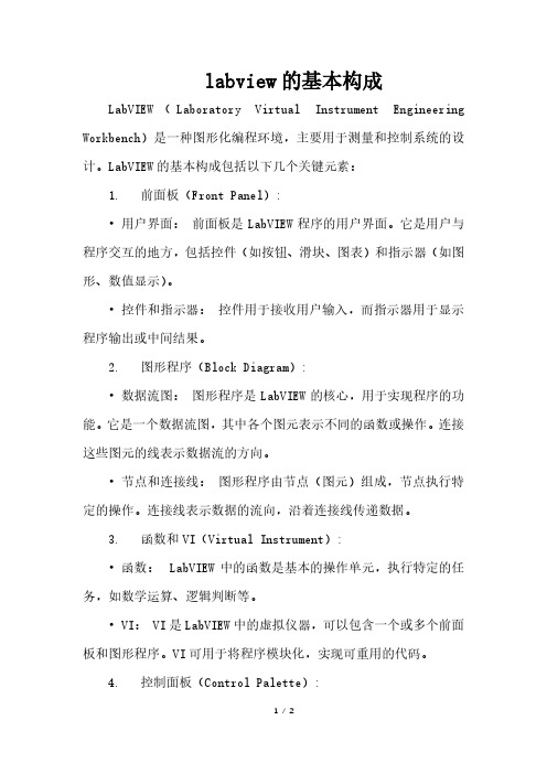
labview的基本构成LabVIEW(Laboratory Virtual Instrument Engineering Workbench)是一种图形化编程环境,主要用于测量和控制系统的设计。
LabVIEW的基本构成包括以下几个关键元素:1. 前面板(Front Panel):•用户界面:前面板是LabVIEW程序的用户界面。
它是用户与程序交互的地方,包括控件(如按钮、滑块、图表)和指示器(如图形、数值显示)。
•控件和指示器:控件用于接收用户输入,而指示器用于显示程序输出或中间结果。
2. 图形程序(Block Diagram):•数据流图:图形程序是LabVIEW的核心,用于实现程序的功能。
它是一个数据流图,其中各个图元表示不同的函数或操作。
连接这些图元的线表示数据流的方向。
•节点和连接线:图形程序由节点(图元)组成,节点执行特定的操作。
连接线表示数据的流向,沿着连接线传递数据。
3. 函数和VI(Virtual Instrument):•函数:LabVIEW中的函数是基本的操作单元,执行特定的任务,如数学运算、逻辑判断等。
• VI: VI是LabVIEW中的虚拟仪器,可以包含一个或多个前面板和图形程序。
VI可用于将程序模块化,实现可重用的代码。
4. 控制面板(Control Palette):•控制和显示元素:控制面板是LabVIEW中包含各种控制和显示元素的工具箱。
用户可以从控制面板中拖拽这些元素到前面板,用于构建用户界面。
5. 工具栏(Toolbar):•编辑和运行:工具栏包含各种工具,如编辑工具、运行工具等,用于编辑程序和执行程序。
6. 项目(Project):•项目资源:项目视图允许用户组织和管理LabVIEW项目,包括VI文件、数据文件、图标等。
项目视图使得对项目中的所有资源进行集中管理变得更加方便。
这些基本构成元素共同形成LabVIEW的整体框架,LabVIEW的独特之处在于其图形化编程环境,使得用户可以通过直观的方式设计、测试和部署测量和控制系统。
labview的使用方法

labview的使用方法LabVIEW(Laboratory Virtual Instrument Engineering Workbench)是一种LabVIEW (Laboratory Virtual Instrument Engineering Workbench)是一种图形化编程语言,主要用于数据采集、仪器控制、数据分析和测试等方面。
以下是使用LabVIEW的基本步骤:1. 安装LabVIEW软件:首先需要从官方网站下载并安装LabVIEW软件。
安装完成后,启动LabVIEW。
2. 创建新项目:在LabVIEW启动界面中,选择“新建”或“打开”一个已有的项目。
如果创建新项目,可以选择不同的模板,如“VI(Virtual Instrument)”、“Control Design”等。
3. 设计前面板(Front Panel):前面板是用户与程序交互的界面,可以放置各种控件(如按钮、滑动条、图表等)来显示数据和接收用户输入。
在左侧的“控件”面板中选择所需的控件,然后将其拖放到前面板上进行布局。
4. 编写程序代码(Block Diagram):在右侧的“块图”面板中编写程序代码。
LabVIEW使用图形化的编程方式,将各种功能模块以图标的形式表示,通过连线连接各个模块来实现程序逻辑。
常用的功能模块包括数学运算、数据处理、信号处理、文件操作等。
5. 调试和运行程序:在编写完程序代码后,需要进行调试以确保程序的正确性。
可以使用断点、单步执行等功能进行调试。
调试完成后,点击工具栏上的“运行”按钮或按F5键运行程序。
6. 保存和导出项目:在完成程序设计和调试后,需要将项目保存为.vi文件。
此外,还可以将程序导出为其他格式,如可执行文件(.exe)、动态链接库(.dll)等。
7. 部署和发布程序:将生成的可执行文件或动态链接库部署到目标计算机上,即可实现程序的功能。
如果需要将程序发布给其他用户,可以将项目打包成安装包或生成Web服务等形式。
LabVIEW常用中英文词汇对照表
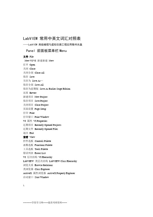
LabVIEW常用中英文词汇对照表——LabVIEW高级编程与虚拟仪器工程应用随书光盘Panel前面板菜单栏Menu文件FileNew VI VI新建新建New打开Open关闭Close关闭全部Close All保存Save另存为Save As…保存全部Save All保存为前期版Save As Earlier Stage Edition还原Revert新建项目New Project保存项目Save Project关闭项目Close Project页面设置Page Setup打印Print打印窗口Print WindowVI属性VI Properties近期项目Recently Opened Projects近期文件Recently Opened Files退出Exit查看View控件选板Controls Palette函数选板Functions Palette工具选板Tools Palette错误列表Errors ListVI层次结构VI HierarchyLabVIEW类层次结构LabVIEW Class Hierarchy浏览关系Browse Relations类浏览器Class ExplorerActiveX属性浏览器ActiveX Property Explorer启动窗口Start Window1.导航窗口Navigation Window工具栏Tools bar编辑EditUndo Window撤消窗口移动Move重做Redo剪切Cut复制Copy粘贴PasteClear删除选择全部Select All当前值设置为默认值Make Current Values Default重新初始化为默认值Reinitalize All to Default自定义控件Customize Control导入图片至剪贴板Import Picture From File…设置Tap键顺序Set Tapping Order删除断线Remove Broken Wires从层次结构中删除断点Remove Breakpoint from Hierarchy创建子VI Create SubVI禁止前面板网格对齐Prohibit the Panel Grid Alignment Align the Options对齐所选项分布所选项Distribute the Options VI Reference HistoryVI修订历史运行时菜单Run-Time Menu查找和替换Find and Replace显示搜索结果Show Search Results项目Project新建项目New Project打开项目Open Project保存项目Save Project关闭项目Close Project添加至项目Add to ProjectGenerate生成生成全部Generate All运行Run筛选视图Select Views文件信息File Information2.属性Properties操作Operate运行Run停止Stop单步步入Single-Step into单步步过Single-Step Over单步步出Single-Step Out断点Breakpoint调用时挂起Suspend when Called结束时打印Print at Completion结束时记录Log at Completion数据记录Data logging切换至运行模式Change to Run Mode连接远程前面板Connect to Remote Panel调试应用程序或共享库Debug Application or Share Library工具Tools仪器InstrumentationMathScript Window MathScript窗口比较Compare性能分析Performance AnalysisSafety安全User Name用户名生成可执行文件Generate Executable DocumentsProject and Generate转换程序生成脚本ConvertScript源代码控制Source Code ControlLLB管理器LLB Manager导入Import共享变量Shared Variable在磁盘上查找VI Find VIs on DiskNI范例管理器Prepare Example VIs for NI Example FinderRemote Panel Connection Manager远程前面板连接管理器Web发布工具Web Publishing Tool…高级Advanced选项Options窗口Window3.显示程序框图Show Block Diagram左右两栏显示The Left and Right上下两栏显示The Up and Down最大化窗口Full Size全部窗口All Windows帮助Help显示即时帮助Show Context Help锁定即时帮助Lock Context Help搜索LabVIEW帮助Search the LabVIEW Help解释错误Explain Error本VI帮助Help for This VI查找范例Find Example查找仪器驱动Find Instrument Driver网络资源Web ResourcesNI MAX Configuration VI ReferenceNI MAX配置VI Reference专利信息Patent InformationAbout LabVIEW LabVIEW关于前面板工具栏Tool Bar in Front PanelRun运行ContinuouslyRun连续运行ExecutionAbort中止执行暂停Pause Settings文本设置Text Dialog字体对话框Font Font应用程序字体Application Font System系统字体FontDialog对话框字体Font当前字体Current Size大小Style样式调整Justify Color颜色Objects对齐对象Align4.上边缘Top Edges垂直中心Vertical Centers下边缘Bottom Edges左边缘Left Edges水平居中Horizontal Centers右边缘Right Edges分布对象Distribute Objects垂直中心Vertical Centers下边缘Bottom Edges垂直间距Vertical Gap垂直压缩Vertical Compress左边缘Left Edges水平居中Horizontal Centers右边缘Right Edges水平间隔Horizontal Gap水平压缩Horizontal Compress调整对象大小Resize Objects最大宽度Maximum Width最大高度Maximum Height最大宽度和高度Maximum Width and Height最小宽度Minimum Width最小高度Minimum Height最小宽度和高度Minimum Width and Height设置宽度和高度Set Width and Height重新排序Reorder组合Group取消组合Ungroup锁定Lock解锁Unlock向前移动Move Forward向后移动Move Backward移至前面Move to Front移至后面Move to Back显示即时帮助Show Context Help图标IconVI属性VI Properties编辑图标Edit Icon5.显示连线板Show Connector查找全部实例Find All Instances添加接线端Add Terminal删除接线端Remove Terminal模式Patterns旋转90度Rotate90Degrees水平翻转Flip Horizontal垂直翻转Flip Vertical断开连接全部接线端Disconnect All Terminals 断开连接本接线端Disconnect This Terminal 接线端类型This Connection Is工具选板Tools Palette操作值Operate Value定位/调整大小/选择Position/Size/Select编辑文本Edit Text进行连线Connect Wire对象快捷菜单Object Shortcut Menu滚动窗口Scroll Window设置/清除断点Set/Clear Breakpoint探针数据Probe Data获取颜色Get Color设置颜色Set Color控件选板Controls Palette新式New Style数值Numeric数值输入控件Numeric Control数值显示控件Numeric Indicator时间标识输入控件Time Stamp Control 时间标识输出控件Time Stamp Indicator 垂直填充滑动杆Vertical Fill Slide垂直指针滑动杆Vertical Pointer Slide垂直进度条Vertical Progress Bar垂直刻度条Vertical Graduated Bar水平填充滑动杆Horizontal Fill Slide 6.水平指针滑动杆Horizontal Pointer Slide 水平进度条Horizontal Progress Bar水平刻度条Horizontal Graduated Bar旋扭Knob转盘Dial量表Gauge仪表Meter液罐Tank温度计Thermometer垂直滚动条Vertical Scrolling Bar水平滚动条Horizontal Scrolling Bar带边框颜色盒Framed Color Box布尔Boolean开关按钮Push Button翘板开关Rocker垂直翘板开关Vert Rocker圆形指示灯Round LED水平摇杆开关Horizontal Toggle Switch 垂直摇杆开关Vertical Toggle Switch方形指示灯Square LED滑动开关Slide Switch垂直滑动杆开关Vertical Slide Switch确定按钮OK Button取消按钮Cancel Button停止按钮Stop Button单选按钮Radio Buttons数组、矩阵与簇Array,Matrix&Cluster数组Array簇Cluster实数矩阵Real Matrix复数矩阵Plural Matrix错误输入3D Error In3D.ctlError Out3D3D.ctl错误输出字符串与路径String&Path 7.字符串输入控件String Control字符串显示控件String Indicator组合框Combo Box文件路径输入控件File Path Control文件路径显示控件File Path Indicator图形Graph波形图表Waveform Chart波形图Waveform GraphXY图Graph XYExpress XY图Express XY Graph强度图表Intensity ChartIntensity Graph强度图数字波形图Digital Waveform Graph 混合信号图Mixed-Signal Graph三维曲面图3D Surface Graph三维参数图3D Parametric Graph三维曲线图3D Curve Graph三维图片控件3D Picture Controls列表与表格List&Table列表框List box多列列表框Multicolumn List box表格Table树形TreeExpress表格Express Table下拉列表与枚举Ring&Enum文本下拉列表Text Ring菜单下拉列表Menu Ring枚举Enum图片下拉列表Picture Ring文本与图片下拉列表Text&Picture Ring容器Containers水平分隔栏Horizontal DividerVertical垂直分隔栏Divider.NET容器.NET Container选项卡控件Tap Control8.子面板Sub PanelActiveX容器ActiveX ContainerI/O波形Waveform数字波形Digital Waveform数字数据Digital Data传统DAQ通道Traditional DAQ ChannelsDAQmax名称控件DAQmax Name ControlsVISA资源名称VISA Resource NameIVI逻辑名称IVI Logical NameField Point IO点Field Point IO PointIMAQ会话句柄IMAQ Session运动资源Motion ResourceCAN控件CAN Controls共享变量控件Shared Variables Controls引用句柄Refnum应用程序引用句柄Application RefnumVI引用句柄VI Refnum控件引用句柄Control Refnum事件发生引用句柄Occurrence Refnum菜单引用句柄Menu RefnumTCP网络连接引用句柄TCP Network Connection RefnumUDP网络连接引用句柄UDP Network Connection Refnum红外线网络连接引用句柄Infrared Ray Network Connection Refnum 蓝牙网络连接引用句柄Bluetooth Network Connection Refnum DataSocket引用句柄DataSocket Refnum字节流文件引用句柄Byte Stream File Refnum数据记录文件引用句柄Data Log File Refnum自动化引用句柄Automatic Refnum.NET引用句柄.NET RefnumEvents Callback回调事件引用句柄Refnum变体与类Variant&Class变体VariantLabVIEW对象LabVIEW Object修饰Decorations9.细线Thin Line粗线Thick Line细分隔线Thin Chiseled Line粗分隔线Thick Chiseled Line带箭头细线Thin Line with Arrow带箭头粗线Thick Line with Arrow标签Label垂直平滑盒Vertical Smooth Box水平平滑盒Horizontal Smooth Box水平按钮框Horizontal Button Box上凸盒Raised Box下凹圆盒Lowered Rounded Box加粗下凹盒Thick Lowered Box上凸盒Raised Box上凸框Raised Frame上凸圆形Raised Circle上凸圆盒Raised Rounded Box上凸左向三角形Raised Left Triangle上凸右向三角形Raised Right Triangle上凸正向三角形Raised Up Triangle上凸反向三角形Raised Down Triangle平面盒Flat Box平面框Flat Frame平面圆形Flat Circle平面圆盒Flat Rounded Box平面左向三角形Flat Left Triangle平面右向三角形Flat Right Triangle平面正向三角形Flat Up Triangle平面反向三角形Flat Down Triangle下凹盒Recessed Box下凹框Recessed Frame下凹圆形Recessed Circle下凹圆盒Recessed Rounded BoxRecessed Left下凹左向三角形Triangle 下凹右向三角形Recessed Right Triangle 下凹正向三角形Recessed Up Triangle下凹反向三角形Recessed Down Triangle 10.系统Dialog Controls系统数值Dialog Numeric系统步进数值控件Dialog Spin ControlDialog String系统字符串Dialog Ring系统下拉列表Dialog Combo系统组合框Dialog Enum系统枚举系统路径控件Dialog Path ControlDialog Label系统标签Dialog Listbox系统列表框系统多列列表框Dialog Multicolumn Listbox系统树形控件Dialog Tree ControlDialog系统表格Table系统垂直滑动杆Dialog Vertical Slide系统水平滑动杆Dialog Horizontal Slide系统垂直指针滑动杆Dialog Vertical Pointer Slide系统水平指针滑动杆Dialog Horizontal Pointer Slide系统垂直进度条Dialog Vertical Progress Bar系统水平进度条Dialog Horizontal Progress Bar系统按钮Dialog Button系统取消按钮Dialog Cancel Button系统单选单按钮Dialog Radio Button系统复选框Dialog Checkbox系统单选按钮Dialog Radio Buttons系统选项卡控件Dialog Tap Control水平滚动条Horizontal Rolling BarRolling Bar垂直滚动条Vertical水平分隔栏(系统)Horizontal Divider(System)垂直分隔栏(系统)Vertical Divider(System)系统下凹框Dialog Recessed Frame系统分隔线Dialog Chiseled Line经典Classic Controls经典数值Classic Numeric数值输入控件Numeric ControlsNumeric Indicator数值显示控件简易数值Simple Numeric11.波形Waveform简易垂直滑动杆Simple Vertical Slide垂直滑动杆Vertical Slide垂直填充滑动杆Vertical Fill Slide垂直指针滑动杆Vertical Pointer Slide液罐Tank温度计Thermometer简易水平滑动杆Simple Horizontal Slide水平滑动杆Horizontal Slide水平填充滑动杆Horizontal Fill Slide水平指针滑动杆Horizontal Pointer Slide旋钮Knob转盘Dial仪表Meter量表Gauge颜色盒Color Box带边框颜色盒Framed Color Box颜色梯度Color Ramp时间标识输入控件Time Stamp Control时间标识显示控件Time Stamp Indicator经典布尔Classic Boolean方形按钮Square Button平面方形按钮Flat Square Button方形指示灯Square LED方形灯Square Light方形单选按钮Square Radio Button圆形按钮Round Button平面圆形按钮Flat Round Button圆形指示灯Round LED圆形灯Round Light圆形单选按钮Round Radio Button垂直开关Vertical Switch水平开关Horizontal Switch垂直摇杆开关Vertical Toggle Switch水平摇杆开关Horizontal Toggle Switch复选框Checkbox带标签方形按钮Labeled Square Button 12.带标签圆形按钮Labeled Round Button带标签矩形按钮Labeled Rectangular Button 带标签椭圆形按钮Labeled Oblong Button 系统按钮Dialog Button系统取消按钮Cancle Button系统复选框Dialog Checkbox系统单选单按钮Dialog Radio Button矩形停止按钮Rectangular Stop Button圆形停止按钮Round Stop Button指示灯按钮LED Button经典单选按钮Classic Radio Buttons方形开关按钮Square Push Button圆形开关按钮Round Push Button垂直滑动杆开关Vertical Slide SwitchSquare Push方形开关按钮2Button2Round Push2Button2圆形开关按钮水平滑动开关Horizontal Slide Switch经典字符串及路径Classic String&Path简易字符串Simple String组合框Combo BoxClassic Array,Matrix经典数组,矩阵与簇&ClusterVariant变体Table&经典列表及表格Classic List GraphClassic经典图形&EnumRing经典下拉列表及枚举ClassicRing系统下拉列表System Containers经典容器Classic I/OI/OClassic经典Refnum Classic经典引用句柄Express NumericControls数值输入控件Switches Buttons&按钮与开关ControlsText文本输入控件Controls用户控件User Indicator数值显示控件Numeric13.指示灯LEDs文本显示控件Text Indicators图形显示控件Graph Indicator控制设计与仿真Control Design and Simulation附加工具包Additional Kit用户控件User Controls选择控件Select a Control…与&程序框图工具栏Tool Bar in Block Diagram运行Run连续运行Run Continuously中止执行Abort Execution暂停Pause高亮度显示执行过程HighLight Execution保存连线值Save Connection Value开始单步执行Start Single Stepping开始单步执行Start Single Stepping单步步出Step Out文本设置Text Settings对齐对象Align Objects分布对象Distribute Objects重新排序Reorder显示即时帮助窗口Show Context Help Window函数选板Functions Palette编程Program结构StructuresFor循环For LoopWhile循环While Loop定时结构Timed Structure条件结构Case Structure14.事件结构Event StructureMathScript节点MathScript Node平铺式顺序结构Flat Sequence Structure层叠式顺序结构Stacked Sequence Structure公式节点Formula Node程序框图禁用结构Block Diagram Banned Structure 条件禁用结构Case Banned Structure反馈节点Feedback Node共享变量Shared Variable局部变量Local Variable全局变量Global Variable修饰Decorations数组Array数组大小Array Size索引数组Index Array替换数组子集Replace Array Subset数组插入Insert Into Array删除数组元素Delete From Array初始化数组Initialize Array创建数组Build Array数组子集Array Subset数组最大值与最小值Array Max&Min重排数组维数Reshape Array一维数组排序Sort1D Array搜索一维数组Search1D Array拆分一维数组Split1D Array反转一维数组Reverse1D Array一维数组移位Rotate1D Array一维数组插值Interpolate1D Array以阈值插值一维数组Threshold1D Array交织一维数组Interleave1D Array抽取一维数组Decimate1D Array二维数组转置Transpose2D Array数组常量Array Constant数组至簇转换Array to Cluster簇至数组转换Cluster to Array数组至矩阵转换Array to Matrix15.矩阵至数组转换Matrix to Array簇与变体Cluster and Variant解除捆绑Unbundle捆绑Bundle按名称解除捆绑Unbundle By Name按名称捆绑Bundle By Name创建簇数组Build Cluster Array索引与捆绑簇数组Index&Bundle Cluster Array簇至数组转换Cluster to Array数组至簇转换Array to Cluster簇常量Cluster Constant转换为变体Changed Into VariantPing-String to V平化字符串至变体转换ariant变体至数据转换Variant to DataVariant to变体至平化字符串转换Ping-String变体属性Variant Properties数值Numeric加Add减Subtract乘Multiply除DivideQuotient&Remainder商与余数转换Conversion 加1IncrementDecrement减1数组元素相加Add Array Elements 数组元素相乘Multiply Array Elements复合运算Compound ArithmeticData Operation数据操作绝对值Absolute Value最近数取整Round To Nearest向下取整Round To-Infinite向上取整Round To+Infinite按2的幂缩放Scale By Power of2复数Complex平方根Square Root16.平方Square取负数Negate倒数Reciprocal符号Sign缩放Scale数值常量Numeric ConstantEnum Constant枚举常量下拉列表常量Ring Constant随机数(0—1)Random Number(0—1)表达式节点Expression Node正无穷大+Infinite负无穷大-Infinite数学与科学常量Additional Numeric ConstantsFile I/OI/O文件写入电子表格文件Write To Spreadsheets FileSpreadsheets File读取电子表格文件Read From写入测量文件Write To Measurement File 读取测量文件Read Measurement File打开/创建/替换文件Open/Create/Replace File关闭文件Close File格式化写入文件Format Into File扫描文件Scan From File写入文本文件Write Characters To File读取文本文件Read Characters From File写入二进制文件Write To Binary FileBinary FileFrom Read读取二进制文件创建路径Build Path拆分路径Strip Path文件常量File Constant配置文件VI Configuration VIs存储Storage高级文件函数Advanced File Functions布尔Boolean与And或Or异或Exclusive Or17.非Not复合运算Compound Arithmetic与非Not And或非Not Or同或Not Exclusive Or蕴含Implies数组元素与操作And Array Elements数组元素或操作Or Array Elements数值至布尔数组转换Number To Boolean Array布尔数组至数值转换Boolean Array To Number布尔值至(0-1)转换Boolean To(0,1)真常量True Constant假常量False Constant字符串String字符串长度String Length连接字符串Concatenate Strings部分字符串String Subset附加字符串函数Additional String Functions替换子字符串Replace Substring搜索替换字符串Search and Replace String匹配模式Match Pattern匹配正则表达式Regular Expression Match格式化日期/时间字符串Format Date/Time String字符串/数值转换String/Number Conversion扫描字符串Scan from String格式化写入字符串Format Into String电子表格字符串至数组转换Spreadsheet String to Array数组至电子表格字符串转换Array to Spreadsheet String字符串/数组/路径转换String/Array/Path Conversion创建文本Build TextTrim White space删除空白转换为大写字母To Upper Case 转换为小写字母To Lower Case空格常量Blank Space ConstantString字符串常量Constant空字符串常量Empty String Constant回车键常量Carriage Return Constant18.换行符常量Line Feed Constant行结束常量End of Line Constant制表符常量Tab Constant比较Comparison等于?Equal?不等于?Not Equal?大于?Greater?小于?Less?大于等于?Greater Or Equal?小于等于?Less Or Equal?等于0?Equal To0?不等于0?Not Equal To0?大于0?Greater Than0?小于0?Less Than0?大于等于0?Greater Or Equal To0?小于等于0?Less Or Equal To0?选择Select最大值与最小值Max&Min判定范围并强制转换In Range and Coerce非法数字/路径/引用句柄?Not A Number/Path/Refnum?Array?空数组?Empty String/Path?路径?Empty空字符串/Digit?十进制数?Decimal Digit?十六进制数?HexDigit?Octal八进制数?Printable?可打印?Space?White空白?Class?Lexical字符类?Comparison比较Time定时Count(ms)时间计数器Tick??等待(ms)Wait(ms)Multiplyms UntilWait Next等待下一个整数倍毫秒Token To Time转换为时间标识StringDate/Time Get获取日期/时间字符串Seconds时间(秒)获取日期/GetDate/TimeIn19.日期/时间至秒转换Date/Time To Seconds秒至日期/时间转换Seconds To Date/Time时间标识常量Time Stamp Constant时间延迟Time Delay已用时间Elapsed Time格式化日期/时间字符串Format Date/Time String对话框与用户界面Dialog and User InterfaceOne Button单按钮对话框Dialog双按钮对话框Two Button Dialog三按钮对话框Three Button Dialog简易错误处理器Simple Error Handler通用错误处理器General Error Handler清除错误Clear Errors合并错误Merge Errors错误代码至错误簇转换Error Cluster From Error Code查找第一个错误Find First ErrorPrompt User To提示用户输入Input显示对话框信息Display Message To User等待前面板活动Wait For Front Panel Activity产生前面板活动Generate Front Panel ActivityColor Box颜色盒常量Constant列表框符号下拉列表控件常量Listbox Sign Ring Controls Constant事件Event菜单MenuCursor游标帮助Help波形Waveform获取波形成分Get Waveform Component创建波形Build Waveform设置波形属性Set Waveform Attribute获取波形属性Get Waveform Attribute模数转换Analog to Digital Waveform数模转换Digital to Analog Waveform索引波形数组Index Waveform ArrayCopy Waveform dt复制波形dt对齐波形时间标识Align Waveform Timestamps获取波形子集Get Waveform Subset20.获取终止时间值Get Final Time Value波形持续时间Waveform DurationScale Delta缩放t按dt Get XY Value获取XY值获取波形时间标识数组Get Waveform Timestamps Array模拟波形Analog Waveform数字波形Digital Waveform波形文件I/O Waveform File I/O应用程序控制Application Control打开应用程序引用Open Application Reference打开VI引用Open VI Reference静态VI引用Static VI Reference关闭引用Close Reference通过引用节点调用Call By Reference NodeProperty Node属性节点调用节点Invoke Node调用链Call Chain转换为特定的类To More Specific Class转换为通用的类To More Generic ClassClass Specifier类说明符常量ConstantVI Server to服务器引用VIIndex VI VI调用父方法Call Father Method获取拖放数据Drag and Drop Access to Data停止Stop退出LabVIEW Quit LabVIEW请求释放内存To Release Memory同步Synchronization通知器操作Notifier Operations队列操作Queue Operations信号量Semaphore集合点Rendezrous事件发生Occurrences首次调用?First Call?图形与声音Graphics&Sound三维图形属性3D Graph Properties21.图片绘制Picture Plots图片函数Picture Functions图形格式Graphics Formulates蜂鸣声Beep声音Sound三维图片控件3D Picture Controls报表生成Report Generation简易文本报表Easy Text Report简易打印VI前面板或说明信息Easy Print VI Panel or Documentation VI说明信息VI Documentation新建报表New Report打印报表Print Report保存报表至文件Save Report to File处置报表Dispose ReportHTML报表HTML Reports OnlySet Report Font设置报表字体Append Report添加报表文本Text添加表格至报表Append Table to Report添加列表至报表Append List to ReportReport Layout报表布局添加前面板图像至报表Append Front Panel Image to Report添加控件图像至报表Append Controls Image to Report添加图像至报表Append Image to Report高级报表生成Advanced Report GenerationReport报表DIAdem报表向导NI DIAdem Report Wizard测量I/OMeasurmentsI/O 仪器I/OInstrumentation I/O仪器驱动程序Instrumentation Drivers串口Serial视觉与运动Vision and Motion数学Mathmatics数值Numeric基本与特殊函数Basic&Special Function线性代数Linear Algebra22.拟合Fitting内插与外推Interpolation and Extrapolation积分与微分Integration and Differentiation概率与统计Probability and Statistics最优化Optimization微分方程Differential Equation几何Geometry多项式Polynomial脚本与公式Script and Formula信号处理Signal DisposeWaveform Generation波形生成Waveform Conditioning波形调理波形测量Waveform Measurement信号生成Signal Generation信号运算Signal Processing窗Windows滤波器Filter谱分析Spectrum Analysis变换Transform逐点Point By Point数据通信Data Communication共享变量Shared VariableLocal Variable局部变量全局变量Global Variable队列操作Queue Operation同步Synchronize协议Agreement互连接口Interconnection Interface库与可执行Libraries and Execution源代码控制Source Code ControlI/O端口Port I/OMultisim Kit工具包Multisim.NET输入设备控制Input Device Control23.控制设计与仿真Control Design and SimulateSignalExpressAcquire SignalsGenerate SignalsCreate SignalsLoad/Save SignalsProcessingAnalysisExpress输入Input信号分析Signal Analysis输出Output信号操作Signal Operation执行过程控制Execution ControlArith/Compare算术与比较启动窗口Start Window新建New项目Project基于模板的VI VI from Template更多More打开Open资源ResourcesLabVIEW New UserLabVIEW新用户LabVIEW入门指南LabVIEW ABC Guide book LabVIEW基础LabVIEW BasicLabVIEW文档指南LabVIEW Documents Guidebook LabVIEW帮助LabVIEW HelpLabVIEW Upgrade LabVIEW升级网络资源Web Resource 论坛Forum培训课程Training Courses范例Examples查找范例Find Examples24.。
NILabVIEW官方入门教程(中文pdf)
目录
关于本用户手册 行文规范.....................................................................................................................................................ix 相关文档.....................................................................................................................................................x
免责条款,见 USICopyrights.chm。
Xerces C++. 本产品包括由 Apache Software Foundation (/) 开发的软件。 Copyright 1999 The Apache Software Foundation. 版权所有。 ICU. Copyright 1995–2003 International Business Machines Corporation and others. 版权所有。 HDF5. NCSA HDF5 (Hierarchical Data Format 5) 软件库和工具。 Copyright 1998, 1999, 2000, 2001, 2003, by the Board of Trustees of the University of Illinois. 版权所有。 Citadel 5. 使用 Citadel 5 的组件适用以下版权。 Copyright © 1994 Hewlett-Packard Company. b64 library. Copyright © 2004–2006, Matthew Wilson and Synesis Software. 版权所有。 Stingray. 本软件包括由 Rogue Wave Software division of Quovadx, Inc 开发的 Stingray 软件。 Copyright 1995–2006, Quovadx, Inc. 版权所有。
LabVIEW中的数据可视化和形界面设计
LabVIEW中的数据可视化和形界面设计LabVIEW(Laboratory Virtual Instrument Engineering Workbench)是一种用于数据获取、处理与可视化的图形化编程环境。
在实验室工作和科学研究中,数据可视化和用户界面设计是两个重要的方面。
本文将介绍LabVIEW中的数据可视化和界面设计的相关内容。
一、LabVIEW简介(200字左右)LabVIEW是由美国国家仪器公司(National Instruments)开发的一款图形化编程软件,旨在帮助工程师和科学家进行各种测量和控制任务。
LabVIEW以其直观的可视化编程环境和强大的功能而被广泛应用于各个领域。
二、数据可视化(400字左右)在科学实验和工程控制中,数据的可视化是非常重要的。
LabVIEW 提供了丰富的工具和函数来实现数据的可视化。
通过简单的拖拽、连接和配置,用户可以创建各种图表、图形和仪表盘,将复杂的数据以直观的方式展示出来。
1. 图表绘制:LabVIEW提供了各种类型的图表控件,如折线图、柱状图、饼图等。
用户可以根据实际需求选择合适的图表类型,并通过配置参数设置图表的样式、颜色和轴标注等。
2. 数据处理与分析:LabVIEW内置了各种数据处理和分析的函数模块,如平均值、滤波、快速傅里叶变换等。
用户可以通过这些函数对采集到的数据进行处理和分析,进而得到更有意义的结果。
3. 3D可视化:除了传统的2D图表外,LabVIEW还支持三维数据的可视化。
用户可以创建三维图表、曲面图等,以展示更为复杂的数据关系。
三、用户界面设计(500字左右)一个简洁、易用的用户界面对于实验和控制系统来说至关重要。
LabVIEW提供了丰富的界面设计工具和控件,使用户能够轻松创建出符合自己需求的用户界面。
1. 控件选择:LabVIEW提供了各种常见的控件,如按钮、滑动条、输入框等。
用户可以根据实际需求选择适合的控件,并进行自定义配置,使界面功能齐全、易于操作。
外文翻译---基于LabVIEW的电流互感器校验仪
附录A LabVIEW Based Instrument Current Transformer CalibratorXin Ai Hal BaoY.H. Song1) NorthChinaElectricPowerUniversity, Beijing, China 1072062)BrunelUniversity. UKABSTRACTThe Virtual Instrument (VI) mainly refers to build all kinds of instruments by software such as LabVIEW,which likes a real instrument buildin a computer. Its' main characteristicsare flexibility, multi-functions, multiple uses for one PC computer, giving high performance, and is less costly. In this paper, the VI technology is applied to the test and measurement of instrument current transformer (TA). By using the LabVIEW, the TA accuracy calibrator was developed. This virtual T.4 calibrator can automatically measure the accuracy of T.4 and can indicate the ratio error and phase error curves. The tests and calibration for the TA show that the virtual TA calibrator can be used in place of the traditional calibrator and is much better than the traditional one. Keywords:Instrument current transformer (TA), TA calibrator, Virtual Instruments, LabVIEW.I. INTRODUCTIONSince 1992 the VXIbus Rev.1.4standard was established by the United States and LabVIEW was presented by the National Instruments co.(Nl), the Virtual Instrument (VI) have lain the foundation for its commercial use. The main characteristic of Virtual Instrument is that it makes instruments by software. Most of the traditional instrument can be developed by VI. The VI is a real instrument made by the personal computer.The Instrument current transformer (TA) is widely used in all kinds of current measurement and it has the functions of protection, isolation and extending the measuring range. With the rapid development of computer measurement and control technology, and with the sequent emergence of current transformer and transducer, there is an increasing number of current transformers with high accuracy and low secondary current. The standard TA secondary current is usually 1A or 5A: some non-standard TA secondary current may be 0 1A or lower. Although we have the technique to make this kind of calibrator by means of hardware such as single chip computer and electroniccircuit, DSP and so on, it will cost too much money for these no-standard calibrator and will take too much time and the calibrator made by these hardware mill not be satisfactory in both function and practicality for designing all kinds of new TA.The calibrator that adopts VI technology not only can meet the requirements of the traditional one but also can satisfy customers with such advantages as multi-functions, convenience, and high ratio between performance and cost. The experiment results indicate that the virtual calibrator can provide excellent condition for TA measurement and design. The VI technology and personal computer must be widely used in the area of calibration on instrument transformer.Ⅱ. THE WORKING PRINCIPLE OF TA CALIBRATOR The error of TA includes ratio error and phase error. The measuring of the error of TA or the calibration of the accuracy of TA usually applies differential measuring method. The method needs a standard TA except the measured TA and a TA calibrator. There is the same turn ratio between the standard and measured T4 and the standard TA's accuracy should be 2 levels higher than the measured one. The calibrator function lies in forming comparison circuits, measuring, and showing the error at all range. The comparison circuit, also referred to the difference measuring principle circuit, is showed in Fig. 1. By measuring the voltage on I, and Rd, calculate the corresponding current. Then the calibrator can indicate the error.When a TA has the same turn ratio between the primary and secondary winding, the self-comparison circuit could be used and is shown in Fig.2. In the figures, TA0 and TAX are standard and TA being measured respectively. Np and Ns are primary and secondary winding turns. ip and io, id, i, are primary currentsecondary standard current, secondary error current, secondary current of TA being measured respectively. Ro and R,R, are secondary winding's resistance ofstandard TA, error currentdetecting resistance, burden resistance ofTA being measured respectively. To and K, Tb. T, are voltage sampling points which can calculate the current In this paper, only voltage between K and T, voltage between Tb and T, are being measured and they represent the voltage on R, and R, respectively.In general, the TA calibrator's principle of the sample resistance should be:1)it can not affect the accuracy of the comparison circuit. In the ideal condition R, and Rd should be 0, but it can not be sampled. So there must be sample resistance, in this paper, R, as shown in Fig, is used;1)the magnitude of the sample resistance should make the sampled standard currentand error current in pro rata and should not have too much difference. The sampled resistance is set by experiment: R, is the secondary standard current sampling resistance andcan be 0.1-0.50, R, is the error current sampling resistance and canbe, R, is the burden resistance and it depends on the TA being measured. E$ sampling the voltage uo and U, on R, and R, respectively, the ratio error and phase error are showed on the LED through some process and calculations.According to the TA error's phase diagram, when io is maximum, the value of id is the ratio error; when io changes from negative to positive and equals to 0, the value of id is the phase error. For the same principle, the relationship is equal to the voltage signal U, and ud. showed in Fig.3. a and b is represent the ratio error and phase error separately. the TA's real ratio error C and phase error 6 can be found out through proper calculation,Where U, is the amplitude of uo The T.4 calibrator doesn't need very high accuracy. 1% to 3% error for the calibrator is enough. Because of the difference measuring principle, the error is the read error of calibrator, that is, the TA's error's error being measured. But the calibrator needs to have a suitable enlargement factor. The calibrator maximum enlargement factor through all channels should be 1000 times.III. THE PRINCIPLE OF VIRTUAL CA LIBRATORThe Virtual Instrument consists of three parts: the external comparison circuit (showed in Fig.1 or Fig.2), data acquisition card (PCI-6023) installed in the PC and the VI program by LabVIEW Then, after the two channels' signal U, and ud come into the PC through the ADC, the rest of the work is done by the software. In this paper we use voltage U, on R, substitute for U, approximatively. The virtual calibrator's work flow chart is shown as follow:1) Set the essential initial values of the virtual calibrator;2) Press the start button to start to work, adjusting the voltage regulator and changing the primarycurrent, let the ratio between primary current and the rated current change from10% to 120%;3) The VI program willgroup the voltage signal U, and ud , then use the digital filter to eliminatethe harmonic:4) Calculatethe root-mean-square (RMS) value of tlx and 14, find out the amplitude of 21;5) Calculate the RMS valve of io (substitute for f, ), i, and the ratio between io and it's rated current and show the results.6) Find out the a and b showed in Fig. 3, calculate the ratio error and phase error and show the results.7) Set the L times loop, record and show the errors acquired by every time,8) Show and print all the results of calibration.9)Stop.The front panel of the virtual calibrator has the Controls, indictor and Switch. The function of Controls is to set the initial value before it works, The function of the Indictor is to show at1 kinds of needed values, including digital, curve and diagram etc.. 'The switch decides the start and stop of the virtual calibrator.Of course, to change the measuring range, the operator needs to adjust the voltage regulator and change the primary current. This operation is necessary like that of the traditional calibration, but the recording for the error in any range is done by the virtual calibration. This confirms the accuracy of recording and relieves the operator's work. The use of virtual calibrator is most interesting.The controls of virtual calibrator include:1) Setting the two sampling (analogue input) channels;2) Setting the magnitude of sampling resistance in the comparison circuit;3) Setting the secondary rated current of measured TA;4) Setting the number of sampling of error curve;The Indictor of virtual calibrator has:1) Showing ratio and phase error, ratio between the primary current and the rated ones in digital;2) Showing ratio and phase error, ratio between the primary) current and the rated ones Incurvesand diagram, where the curveinclude the active sampling points and function fitting curves;3) Showing the error for the ratio between the primary current and the rated current from 10% to 1 20°%;4) Showing the waveform of standard and error current, digital value of amplitude;5) Showing of digita1 RMS value the standard and error current;6) Showing the pole of TA in the comparison circuit;The above shows that the function of virtual calibrator is greatly expended that of the traditional ones. 7111s kind of calibrator is not only convenient to use, but also makes the performance of the calibrator much better. From the function that shows the waveform, we canfindout if there are some harmonics in the current, and confirm the accuracy for the calibrator.IV. EXPERIMENTThe virtual calibrator is mainly characterized by the flexibility compared with the traditional ones. Although the front panel has many functions, they can be easily extended by the user. So the virtual calibrator is of important value for the non-standard TA calibration.In the experiment, the primary current produce by a step-up current transformer and its' current controlled by a voltage regulator. Through fitting the comparison circuit, the measuring range of the virtual calibrator canbe set in any value. This paper gives SA and 0.1A two kinds of TA’s calibration experiment. The parameter and method, results are presented below.A. 5A TA experimentThe parameter of TA being measured is:Because of the 1:1 ratio of turn, the calibration for it doesn't need standard TA. The calibration circuit show in Fig2 We can apply self ca libration method to measure it’s accuracy. The results are presented in the Ftg.4 and Fig5 and show that this TA's accuracy can be defined as 0.5 degree.B. 0.1A TA experimentThe parameter of standard TA:From the Fig4 and 5, the accuracy of the TA being measured can be defined as 0.5 degree. In the experiment, the input signal of virtual calibrator should be properly grounded to avoid the disturbance. The sampling resistance in the comparison circuit should use precise ones and with no induction.V. CONCLUSIONSThe VI technique is one of the new scientific and technique productions. The appearance of VI is called“Revolution of Measuring and Control Technology”. According to the development of the software and hardware for computers, the VI t~hn01Ogy will have more developing space. The VIS will replace most of the traditional ones in the 21th century. With its flexibility, the virtual calibrator can measure any kind of T.4 including standard and non-standard ones. But the traditional calibrator can not measure most of the non-standard TA. It can record and save, display the data automatically. The method presented in this paper gives a new way to make he TA calibration. The main characteristics of the virtual calibrator are:1) Flexibility, virtual calibrator is mainly made of LabVIEW software and can be easilymodifiedby rewrite some software;2.) Multi function, VI is designed on PC. It has waveform indictor, parameter controls and so on.At the time wecalibrating a TKs accuracy, these functions can indicate many information such as waveform quality and so on;3) Convenience to carry and use;4) High efficiency and accuracy.;5) High ratio between performance and cost;6) For multiple use in one PC.7) It can record and save, display the calibration data automatically.基于LabVIEW的电流互感器校验仪Xin Ai Hai Bao T.H. Song---布鲁塞尔大学摘要虚拟仪器(VI),指的是利用软件在计算机上建立各种各样的仪器,比如说LabVIEW,就象是真的建立在计算机上的仪器一样。
LabVIEW数据采集系统的设计与实现
随着计算机技术的迅速发展,虚拟仪器正逐渐成为测试领域的发展方向。
虚拟仪器的概念是由美国NI公司提出来的,是指在通用的计算机平台上,用户根据自己的需求定义和设计具有测试功能的仪器系统,即虚拟仪器是由用户利用一些基本硬件及软件编程技术组成的各种各样的仪器系统。
虚拟仪器的三大主要功能是:数据采集;数据测试和分析;结果输出显示。
数据采集是一切测试测量过程的第一步。
本数据采集系统就是一个虚拟仪器系统,它的任务主要是实现对燃料电池汽车上锂动力电池组电压电流的采集。
由于电压和电流的范围很大(电压300多伏特,电流±100多安培),因此需要外接信号调理电路,使信号变换到数据采集设备的输入范围之内。
电压采用电阻分压,比例为1:100;电流采用霍耳传感器(1:2000),输出是电流信号,而且输出信号较弱,因而接入一个40(3)单通道最高采样速率达1.25MS/s,多通道时最高1MS/s(时分复用);(4)电压范围最大为±10V(可编程);(5)板上自带4096字内存(FIFO)等。
操作系统支持Windows2000和XP等操作系统,软件平台推荐使用LabVIEW、LabWindows/CVI和Measu-rementStudio,也可使用VB、VC++等软件。
需要提及的是USB6251不再支持传统的NI-DAQ,只支持NI-DAQmx驱动程序。
2.2LabVIEW简介LabVIEW是目前较为成功、应用广泛的虚拟仪器软件开发环境,LabVIEW(LaboratoryVirtualInstrumentEngineeringWorkbench,实验室虚拟仪器工作平台)是NI公司在1986年首次推出的,最新版本为LabVIEW8.2。
它是一个高效的图形化程序设计环境,结合了简单易用的图形式开发环境与灵活强大的G编程语言;提供了一个直觉式的环境,与测量紧密结合,在这个平台上,各种领域的专业工程师和科学家们通过定义和连接代表各种功能模块的图标来方便迅速地建立高水平的应用程序;支持多种系统平台,在任何一个平台上开发的LabVIEW应用程序可直接移植到其它平台上。
使用LabVIEW进行人机交互界面设计
使用LabVIEW进行人机交互界面设计LabVIEW(Laboratory Virtual Instrument Engineering Workbench)是一款功能强大的图形化编程语言和开发环境,广泛应用于科学研究、工程控制、教育培训等领域。
它提供了丰富的开发工具和库,使得开发者可以轻松地构建各种应用程序,其中包括人机交互界面设计。
本文将介绍如何使用LabVIEW来进行人机交互界面设计。
一、LabVIEW概述LabVIEW是由美国国家仪器公司(National Instruments)开发的一款图形化编程软件。
它的特点是以数据流图为基本编程模型,开发者通过将各种功能模块(称为虚拟仪器)以图形化的方式连接起来,完成程序的设计与开发。
LabVIEW具有良好的可视化特性和模块化设计,使得人机交互界面设计变得简单而高效。
二、LabVIEW界面设计基础在LabVIEW中进行人机交互界面设计的基础是控件和面板。
控件是用来接收用户输入或展示输出结果的元素,例如按钮、滑块、文本框等;面板是控件的容器,用于布局和组织控件。
LabVIEW提供了丰富的控件库,开发者可以根据需求选择合适的控件。
三、创建用户界面1. 打开LabVIEW软件,创建一个新的VI(Virtual Instrument);2. 在界面菜单中选择Controls Palette,浏览并选择适合项目需求的控件;3. 将选中的控件拖拽到面板上,布局和调整它们的位置和大小,以便形成一个直观、友好的界面;4. 对每个控件设置属性,包括名称、标签和默认值等;5. 针对每个控件添加事件处理程序,以便实现相应的功能逻辑。
四、实现交互功能1. 针对各个控件的事件处理程序,编写相应的功能模块;2. 利用LabVIEW提供的模块化设计能力,将这些功能模块组合起来,构建一个完整的交互系统;3. 添加对外部数据源或设备的接口,例如传感器数据的输入和执行器的控制;4. 调试和验证交互功能,确保系统的正常运行,并进行必要的修改和优化。
- 1、下载文档前请自行甄别文档内容的完整性,平台不提供额外的编辑、内容补充、找答案等附加服务。
- 2、"仅部分预览"的文档,不可在线预览部分如存在完整性等问题,可反馈申请退款(可完整预览的文档不适用该条件!)。
- 3、如文档侵犯您的权益,请联系客服反馈,我们会尽快为您处理(人工客服工作时间:9:00-18:30)。
LabVIEWLabVIEW is a highly productive graphical programming language for building data acquisition and instrumentation systems. With LabVIEW, you quickly create user interfaces that give you interactive control of your software system. To specify your system functionality, you simply assemble block diagrams – a natural design notation for scientists and engineers. Its tight integration with measurement hardware facilitates rapid development of data acquisition, analysis, and presentation solutions. LabVIEW contains powerful built-in measurement analysis and a graphical compiler for optimum performance. LabVIEW is available for Windows 2000/NT/Me/9x, Mac OS, Linux, Sun Solaris, and HP-UX, and comes in three different development system options.Faster DevelopmentLabVIEW accelerates development over traditional programming by 4 to 10 times! With the modularity and hierarchical structure of LabVIEW, you can prototype, design, and modify systems in a short amount of time. You can also reuse LabVIEW code easily and quickly in other applications.Better InvestmentUsing a LabVIEW system, each user has access to a complete instrumentation laboratory at less than the cost of a single commercial instrument. In addition, user configurable LabVIEW systems are flexible enough to adapt to technology changes, resulting in a better long-term investment.Optimal PerformanceAll LabVIEW applications execute at compiled speed for optimal performance. With the LabVIEW Professional Development System or Application Builder, you can build stand-alone executables or DLLs for secure distribution of your code. You can even create shared librariesor DLLs to call LabVIEW code from other programming languages.Open Development EnvironmentWith the open development environment of LabVIEW, you can connect to other applications through ActiveX, the Web, DLLs, shared libraries, SQL (for databases), DataSocket, TCP/IP, and numerous other protocols. Use LabVIEW to quickly create networked measurement and automation systems that integrate the latest technologies in Web publishing and remote data sharing. LabVIEW also has driver libraries available for plug-in data acquisition, signal conditioning, GPIB, VXI,PXI, computer-based instruments, serial protocols, image acquisition, and motion control. In addition to the LabVIEW development systems, National Instruments offers a variety of add-on modules and toolsets that extend the functionality of LabVIEW. This enables you to quickly build customizable, robust measurement and automation systems.LabVIEW Datalogging and Supervisory Control ModuleFor high channel count and distributed applications, the LabVIEW Data logging and Supervisory Control Module provides a complete solution. This module delivers I/O management, event logging and alarm management, distributed logging, historical and real-time trending, built-in security, configurable networking features, OPC device connectivity, and over 3,300 built-in graphics.LabVIEW Real-TimeFor applications that require real-time performance, National Instruments offers LabVIEW Real-Time. LabVIEW Real-Time downloads standard LabVIEW code to a dedicated hardware target running a real-time operating system independent from Windows.LabVIEW Vision Development ModuleThe LabVIEW Vision Development Module is for scientists, automation engineers, and technicians who are developing LabVIEW machine vision andscientific imaging applications. The LabVIEW Vision Development Module includes IMAQ Vision, a library of vision functions, and IMAQ Vision Builder, an interactive environment for vision applications. Unlike any other vision products, IMAQ Vision Builder and IMAQ Vision work together to simplify vision software development so that you can apply vision to your measurement and automation applications.Countless ApplicationsLabVIEW applications are implemented in many industries worldwide including automotive, telecommunications, aerospace, semiconductor, electronic design and production, process control, biomedical, and many others. Applications cover all phases of product development from research to design to production and to service. By leveraging LabVIEW throughout your organization you can save time and money by sharing information and software.Test and MeasurementLabVIEW has become an industry-standard development tool for test and measurement applications. With Test Stand, LabVIEW-based test programs, and the industry’s largest instrument driver library, you have a single, consistent development and execution environment for your entire system.Process Control and Factory AutomationLabVIEW is used in numerous process control and factory automation applications. Many scientists and engineers look to LabVIEW for the high speed, high channel count measurement and control that graphical programming offers. For large, complex industrial automation and control applications, the LabVIEW Data logging and Supervisory Control Module provides the same graphical programming as LabVIEW, but is designed specifically for monitoring large numbers of I/O points, communicating with industrial controllers and networks, and providing PC-based control.Machine Monitoring and ControlLabVIEW is ideal for machine monitoring and predictive maintenance applications that need deterministic control, vibration analysis, vision and image processing, and motion control. With the LabVIEW platform of products including LabVIEW Real-Time for real-time deterministic control and the LabVIEW Data logging and Supervisory Control Module, scientists and engineers can create powerful machine monitoring and control applications quickly and accurately.Research and AnalysisThe integrated LabVIEW measurement analysis library provides everything you need in an analysis package. Scientists and researchers have used LabVIEW to analyze and compute real results for biomedical, aerospace, and energy research applications, and in numerous other industries. The available signal generation and processing, digital filtering, windowing, curve-fitting, For specialized analysis, such as joint time-frequency analysis, wavelets, and model-based spectral analysis, LabVIEW offers the specially designed Signal Processing Toolset. The Sound and Vibration Toolset offers octave analysis, averaged and nonaveraged frequency analysis, transient analysis, weighted filtering, and sound-level measurement, and more.Draw Your Own SolutionWith LabVIEW, you build graphical programs called virtual instruments (VIs) instead of writing text-based programs. You quickly create front panel user interfaces that give you the interactive control of your system. To add functionality to the user interface, you intuitively assemble block diagrams – a natural design notation for engineers and scientists.Create the Front PanelOn the front panel of your VI, you place the controls and data displays for your system by selecting objects from the Controls palette, such as numeric displays, meters, gauges, thermometers, LEDs, charts, and graphs.When you complete and run your VI, you use the front panel to control your system whether you move a slide, zoom in on a graph, or enter a value with the keyboard.Construct the Graphical Block DiagramTo program the VI, you construct the block diagram without worrying about the syntactical details of text-based programming languages. You do this by selecting objects (icons) from the Functions palette and connecting them together with wires to transfer data among block diagram objects. These objects include simple arithmetic functions, advanced acquisition and analysis routines, network and file I/O operations, and more.Dataflow ProgrammingLabVIEW uses a patented dataflow programming model that frees you from the linear architecture of text-based programming languages. Because the execution order in LabVIEW is determined by the flow of data between nodes, and not by sequential lines of text, you can create block diagrams that execute multiple operations in parallel. Consequently, LabVIEW is a multitasking system capable of running multiple execution threads and multiple VIs in parallel.Modularity and HierarchyLabVIEW VIs are modular in design, so any VI can run by itself or as part of another VI. You can even create icons for your own VIs, so you can design a hierarchy of VIs and subVIs that serve as application building blocks. You can modify, interchange, and combine them with other VIs to meet your changing application needs.Graphical CompilerIn many applications, execution speed is critical. LabVIEW is the only graphical programming system with a compiler that generates optimized code with execution speeds comparable to compiled C programs. You can evenuse the LabVIEW profiler to analyze and optimize time-critical operations. Consequently, you increase your productivity with graphical programming without sacrificing execution speed.Measurements and MathematicsLabVIEW includes a variety of other measurement analysis tools. Examples include curve fitting, signal generation, peak detection, and probability and statistics. Measurement analysis functions can determine signal characteristics such as DC/RMS levels, total harmonic distortion (THD), impulse response, frequency response, and cross-power spectrum. LabVIEW users can also deploy numerical tools for solving differential equations, optimization, root finding, and other mathematical problems. In addition, you can extend these built-in capabilities by entering MATLAB or HiQ scripts directly in your LabVIEW programs. For charting and graphing, you can rely on the built-in LabVIEW 2D and 3D visualization tools. 2D tools include features such as autoscaling X and Y ranges, reconfigurable attributes (point/line styles, colors, and more) and cursors. Microsoft Windows users can employ OpenGL-based 3D graphs and then dynamically rotate, zoom, and pan these graphs with the mouse.Complex Measurements Made EasyDespite the complexity of the underlying algorithms that implement these functions, you will find them easy to use. For example, a set of built-in measurement functions uses the new waveform data type to accept real-world, time-domain signal inputs directly from DAQ hardware and report results ready for charting, graphing, or the next stage of signal processing.Development SystemThe LabVIEW Professional Development System facilitates the development of high-end, sophisticated instrumentation systems for developers working in teams, users developing large suites of VIs, orprogrammers needing to adhere to stringent quality standards. Built on the Full Development System, the Professional Development System also includes the LabVIEW Application Builder for building stand-alone executables and shared libraries (DLLs) and creating distribution kits. In addition, the development system furnishes source code control tools and offers utilities for quantitatively measuring the complexity of your applications. With graphical differencing, you can quickly identify both cosmetic and functional differences between two LabVIEW applications. We include programming standards and style guides that provide direction for consistent LabVIEW programming methodology. The system also contains quality standards documents that discuss the steps LabVIEW users must follow to meet internal regulations or other strict quality standards such as ISO 9000 certification or FDA approval. The Professional Development System operates on Windows 2000/NT/Me/9x, Mac OS, Sun, HP-UX, and Linux.LabVIEW Full Development SystemThe LabVIEW Full Development System equips you with all of the tools you need to develop instrumentation systems. It includes GPIB, VISA, VXI,RS-232, DAQ, and instrument driver libraries for data acquisition and instrument control. The measurement analysis libraries add DC/RMS measurements, single tone analysis, harmonic distortion analysis, SINAD analysis, limit testing, signal generation capabilities, signal processing, digital filtering, windowing, curve fitting, statistics, and a myriad of linear algebra and mathematical functions. The development system also provides functions for direct access to DLLs, ActiveX, and other external code. Other features of the system include Web publishing tools, advanced report generation tools, the ability to call MATLAB and HiQ scripts, 3D surface, line, and contour graphs*, and custom graphics and animation. The Full Development System operates on Windows2000/NT/Me/9x, Mac OS, Sun, HP-UX, and Linux.LabVIEW Base PackageUse the LabVIEW Base Package, the minimum LabVIEW configuration, for developing data acquisition and analysis, instrument control,and basic data presentation. The Base Package operates on Windows 2000/NT/Me/9x.Debug License for LabVIEWIf you deploy LabVIEW applications, including LabVIEW tests for use with Test Stand, the debug license allows you to install the LabVIEW development system on the target machines so you can step into your test code for complete test debugging. This license is not intended for program development.虚拟仪器(LabVIEW)虚拟仪器是一种高效用于构建数据采集与检测系统图形化编程语言。