故障指示器EKL1使用说明书
开关状态指示仪说明书

3.6 自动加热除湿控制及温湿度数字显示功能
可带 2 路温湿度传感器及输出接点,可显示现场的温湿度数值,并且用户可根据需要自行的设置 加热/除湿/排风输出的上下限。当环境湿度大于上限值或其温度小于下限值时,启动加热,湿度小于 下限值或温度大于上限值时,停止加热;当环境温度≥40℃时,无条件停止加热,防止过热损伤;当 加热断器线时,断线报警输出。
YTK-93MT 系列
开关状态显控装置
使 用 说 明 书
上海一天电气有限公司 安徽一天电气技术有限公司
YTK-93MT 系列开关状态显控装置使用说明书
目录
1 产品概述.............................................................................. 3 2 技术指标.............................................................................. 3 3 主要功能.............................................................................. 3 3.1 断路器状态显示 .............................................................................................................................................4 3.2 手车位置显示 .................................................................................................................................................4 3.3 接地开关位置显示 .........................................................................................................................................4 3.4 弹簧储能显示 .................................................................................................................................................4 3.5 带电显示及闭锁功能 .....................................................................................................................................4 3.6 自动加热除湿控制及温湿度数字显示功能 .................................................................................................4 3.7 双电源自动转换 .............................................................................................................................................4 3.8 人体感应探头 .................................................................................................................................................4 3.9 智能语音防误提示功能 .................................................................................................................................4 3.10 分合闸功能 ...................................................................................................................................................5 3.11 触点及电缆测温功能 ..................................................................................................................................5 3.12 通讯功能 .......................................................................................................................................................5 4 产品型号.............................................................................. 6 5 安装尺寸与接线图...................................................................... 6 5.1 安装尺寸(开孔尺寸:249mm×173mm) .........................................................................................................6 5.2 接线图 .............................................................................................................................................................7 6 显示与设置说明........................................................................ 7 6.1 显示 ..............................................................................................................................................................7 6.2 触点测温显示 .................................................................................................................................................8 6.3 设置说明 ......................................................................................................................................................8 7 运输与贮存........................................................................... 10
E-1000温控器中文说明书
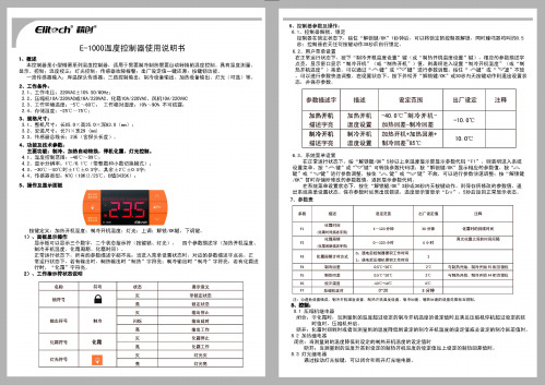
灯先符号
回
灯先灭
灯光亮
8 . 3 盯先缰 电揭
通过按动灯先按键
亮
•
国
9 出厂参数一键还原
在 锁 定状$下钱佳 " A " 植待盟 10砂 U 上 ,这时E示 "rES"3秒钟在追3秒钟内按"胆锁链/OK " 键, 可 以对温植棉 参盟进行 出广剧认值的恢重 并且示 "YES " , 保存参娘时如果出现错误 温度显示 盲显示 'Er r" , :3秒后进入正常显示状击4 理议 此时温控器重时通 电 h 1 0、接线固
()-- 120 小时
E 小时
化嚣闰lVI ìt时万宝t
割琦回 矗
口.遇电后回咽j帽'积工作时司 l : iM晤后E细帆禀积工悻时司
A
与制凯奸'由制冲开甜'"仨直柑位 与制1A开拍制,噜开蛐 问""甜位
0,5'( : "'1 0'(;
05咽c_,口℃ 1口 'C -lO'C
符号
核态 灭
罪事意义 非锁定状态 注 锁定状态
设定范围 40.0 'C 甸和l 冷 开 机
2.4
存储温度
25'( … 75'C
3、坦幅R寸z
3.1 、 直矶尺寸长85. 0X 商35 , Q X 罩63 , 8 (rrm) 3. 2 、 安装尺 寸长 71 X 宽 29 (m叫
加热固 差串l冷 回 差
加热开机+加热回差+ 制冷回 差 "85"(:
.,.
AK8S-I带电指示及短路故障综合指示仪使用说明书
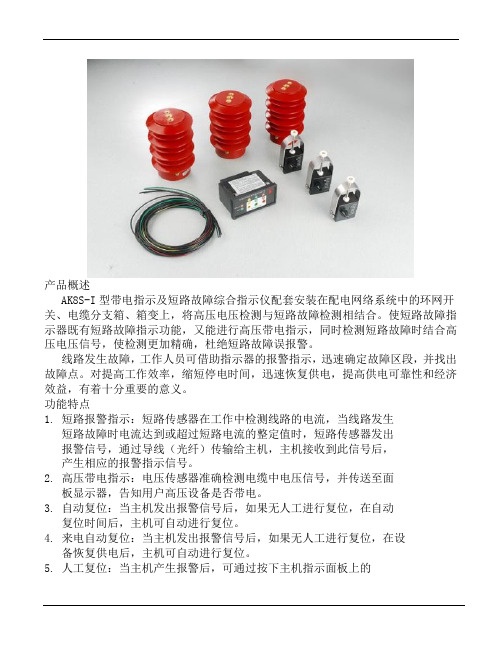
产品概述AK8S-I型带电指示及短路故障综合指示仪配套安装在配电网络系统中的环网开关、电缆分支箱、箱变上,将高压电压检测与短路故障检测相结合。
使短路故障指示器既有短路故障指示功能,又能进行高压带电指示,同时检测短路故障时结合高压电压信号,使检测更加精确,杜绝短路故障误报警。
线路发生故障,工作人员可借助指示器的报警指示,迅速确定故障区段,并找出故障点。
对提高工作效率,缩短停电时间,迅速恢复供电,提高供电可靠性和经济效益,有着十分重要的意义。
功能特点1. 短路报警指示:短路传感器在工作中检测线路的电流,当线路发生短路故障时电流达到或超过短路电流的整定值时,短路传感器发出报警信号,通过导线(光纤)传输给主机,主机接收到此信号后,产生相应的报警指示信号。
2. 高压带电指示:电压传感器准确检测电缆中电压信号,并传送至面板显示器,告知用户高压设备是否带电。
3. 自动复位:当主机发出报警信号后,如果无人工进行复位,在自动复位时间后,主机可自动进行复位。
4. 来电自动复位:当主机发出报警信号后,如果无人工进行复位,在设备恢复供电后,主机可自动进行复位。
5. 人工复位:当主机产生报警后,可通过按下主机指示面板上的“Reset / Test ”按钮解除报警。
6. 自动化:主机产生相应的报警指示信号后,可将报警信号输出远传。
主机也可接收远方的复位信号,对主机进行远程复位操作。
7. 带电闭锁及核相验电:主机能够指示带电闭锁工作情况;并配有验电核相孔,具备三相验电及三相核相功能。
8.测试:面板指示器可进行自检工作。
在正常状态下(无报警信号),可按住前面板的“Reset / Test ”按钮并保持3秒,面板上的短路、接地报警指示灯闪烁,故障远传继电器吸合,说明工作状态正常,再按下此钮可恢复成常态或者按照设定的自动复位时间自动复位。
9.电池低电量报警指示:当指示器内电池电压从3.6V 降至2.7V 时,产生报警信号,以提示维修人员更换电池。
电子指示器操作手册说明书

Electronic Indicator Operating Manual Backlight Analog DisplayAnalog Visual Display Incremental Measuring ModeSPC Cables USB, MTI, RS232 Measuring System in English or Metric Travel ReverseGreen BacklightYellow Tolerance Warning Backlight Red Out-of-tolerance Warning Backlight User-adjustable Backlight Brightness T.I.R. with Low & High Storage Recall Includes Single Gage Simple Data Collection (One Indicator Per Computer)USB/AC Power CableFloating ZeroProgrammable Lock Combination User Tolerance Settings (high & low) Up to 4 User Changeable Resolutions Inch/Metric Display Conversion Maximum Reading HoldDisplay/Freeze Reading Hold Minimum Reading HoldAbsolute/Preset Measuring Mode Large LCD Display2TABLE OF CONTENTSPower Source (3)Button Functions (3)Summary Chart For Analog Button Actions (4)Display-Operating Prompts & Conditions (5)Power On/Off (6)Travel Reverse Toggle (6)Change Units (6)Hold Mode (7)Tolerance On/Off (7)Tolerance Settings (8)Set High Tolerance Number (8)Set Low Tolerance Number (9)Change LCD Backlight Brightness Level (10)Set Absolute Number (11)Lock Toggle (12)Lock Combination (12)Reset to Factory Defaults (13)Verify Data I/O Type (13)Set Gage Resolution (14)Display Setup Mode (14)TIR Mode (15)Custom Applications (16)3POWER SOURCEData I/O ConnectorPower is provided through the data I/O connector. The power cable that isincluded can be used on a USB port or a 110 volt outlet. For special fixturing or applications where the indicator is integrated with another piece of equipment, a ripple-free 5 VDC regulated voltage source is required.BUTTON FUNCTIONSKeyFunction ControlledOFF/MODE O ff – turns indicator off M ODE – controls absolutenumbers & display setupON/CLR On – turns indicator on C LR – resets the LockToggle , Data I/O Type , gage resolution , and Display setup modeHOLDA llows you to hold the value on the displayIN/MM C ontrols the display units (default is English)2ND Controls the Lock Toggle , Data I/O Type, gage resolution , Travel Reverse and Display setup mode TOL C ontrols Low , High and On tolerance settingsSUMMARY CHART FOR ANALOG BUTTON ACTIONS Button actions occur on the press of the button in most cases. Some button presses will have the action occur on the release of the button press. For example, when the ‘ON/CLR’ button is used to clear the display, the action is to happen on the release of the button. When the ‘ON/CLR’ button is used as the 2nd function in a sequence of button pushes, the action can be on the press of the button. Whenever a button press requires a continuous press to scroll through some selection process, the action of the button is on the release of the button.45DISPLAY-OPERATING PROMPTS & CONDITIONSFeatures Indicator is in preset number setting Indicator ready for 2nd or 3rd IN for for Metric Runout (Peak (valley (Display countsup with inward spindle movement for INCR and ABS measurement modes.for INCR and ABS measurement modes.6OPERATING INSTRUCTIONSPower On/OffTo turn the unit on, press ON/CLRoff, press OFF/MODE .Travel Reverse Toggle To change count direction:Press 2ND button, then press the IN/MM button.Note: When arrow is pointed down , the display counts down with inward spindle movement for INCR and ABS .When the arrow is pointed up ,display counts up with inward spindle movement. For most applications this is the normal setting.Change UnitsTo change the display units, press the IN/MM button.Default unit of measure is set at the factory for English or metric scales.Hold ModeAllows you to hold the value on thedisplay according to the specified mode.Press HOLD to toggle hold mode on and off.MAX – Holds and displays the highest reading attained.MIN – Holds and displays the lowest reading attained.FRZ T o select type of HOLD (MAX , MIN , FRZ ): Press HOLD until desired feature is flashing, then release HOLD.Note: Pressing ON/CLR button resets indicator to spindle position except in FRZ; resets to zeroTolerance On/OffPress TOL to toggle tolerance mode on and off. If no tolerances areprogrammed into the gage, then tol is displayed to indicate an invalidtolerance setting and the HIGH and/or LOW icons flash on and off.When the tolerance settings are incorrect (high, low, or both) thecorresponding icon or icons will flash.8Tolerance SettingsContinuously press the TOL button to activate the tolerance menu (LOW, HIGH, ON) and view the low and high tolerance settings.If no preset tolerance number isset into the gage then zero will be displayed.When viewing low or high, that icon will flash.Set High T olerance NumberWhile in tolerance mode, continuously press the TOL (CHANGE) button until the HIGH icon flashes, then release button. Press 2ND button (2ND icon should appear on the display). Press the TOL (CHANGE) button.Use the secondary function buttons, CHANGE and MOvE, to set your tolerance setting. After you have set your high tolerance setting, press AppLy to store numbers to memory.9Set Low T olerance NumberWhile in tolerance mode, continuously press the TOL (CHANGE ) button until the LOW icon flashes, then release button. Press 2ND button (2ND icon should appear on the display). Press the TOL (CHANGE ) button.Use the secondary function buttons, CHANGE and MOvE, to set your tolerance setting. After you have set your low tolerance setting, press AppLy to store numbers to memory.the reading value is more than 80% of the high or low set tolerance (if yellow warning feature is turned on), and will turn red when readings are out of tolerance.The tolerance function must be programmed and turned on for the LCD to turn red.Green and red LCD brightness levels can be adjusted. Y ellow warningbrightness is based on the brightness of the programmed green and red LCD settings. The yellow warning can be turned on or off.Operator can program the color in this sequence: green, red and then yellow.10T o change brightness level of the LCD backlight and turn yellow warning on/off: Press and release the 2ND button. Press and release the HOLD button. Use the CHANGE (TOL) button to scroll through green brightness levels. Use the AppLy (HOLD) button to set the green brightness level. Use the CHANGE (TOL) button to scroll through red brightness levels. Use the AppLy (HOLD) button to set the red brightness level. Use the CHANGE (TOL) button to turn the yellow “Warn” on or off. Use the AppLy (HOLD) button to set ON or OFF.11Set Absolute NumberContinuously press the OFF/MODE button. When the icon on the LCD flashes above the ABS lettering, release the OFF/MODE button. If no preset number is stored in indicator ABS will show on display.To change to absolute number (preset number), press 2ND button; 2ND icon should appear on the display. Press the TOL (CHANGE ) button.Use the secondary function buttons, CHANGE and MOvE , to set your absolute number.Press MOvE until the +/- or digit to be set is blinking.Press the CHANGE button to reverse the +/- sign or change the value of the blinking digit. Repeat until the desired number is entered. Press AppLy to store absolute number to memory.12Lock ToggleWhen the LOCK is on, all of the settingmodes are disabled, and all 2nd and 3rdfunctions are disabled except the lock/unlock sequence.Press the 2ND button (2ND icon shouldappear on the display). Press ON/CLR.Press TOL. A key symbol will appear on thedisplay when features are locked.To unlock, repeat button sequence.Lock CombinationPress the 2ND button (2ND icon shouldappear on the display), then press ON/CLR. Continuously press TOL until 000 appearson the display.Use the CHANGE and MOvE button to enteryour lock combination. After you have setyour 3 digit lock combination press AppLy.A key symbol will appear on the display andyour 3 digit combination is stored in memory. WARNING: To change functions afterthe indicator has been locked with acombination, the correct combination mustbe applied.To unlock, repeat button sequence andPlease contact the factory if the Lock Combination is lost.Reset to Factory DefaultsThis will set all features and functions back to the factory default settings.Press the 2ND button (2ND icon should appear on the display),followed by ON/CLR , then press IN/MM .Note: Factory defaults cannot be reset if the LOCK feature is on.Verify Data I/O TypeTo view the Data I/O Type Output, press the 2ND button. The 2ND icon will appear on the display. Press ON/CLR . Press 2ND . Format information is displayed on the LCD. USB , SER , MTI , or BIpASS will appear on the LCD.To exit: Repeat button sequence.14Set Gage ResolutionFor the change resolution feature: Press2ND, press ON/CLR, then press HOLD.After that, each press of the CHANGE Button (TOL) steps through the available resolution options: .001˝, .0005˝, .0001˝ or .00005˝ **Note: Only resolutions coarser than resolution of purchased indicator are available.Analog graduations are set to match gage resolution. Press the AppLy button to store Display Setup ModeTo change the display configuration, press the 2ND button, followed by the ON/CLR button. Then press the OFF/MODE button to enter the display configuration setting mode.The whole display flashes.Press CHANGE to cycle through the display options and choose AppLy to save the current display configuration. There are five display options. For example, the analog display can be turned off or thenumbers can be turned off.15TIR ModeTotal Indicator Runout (TIR ) mode ignores travel direction, insteadmeasuring the difference between peak and valley (MAX and MIN ) values.To enter TIR Mode, continuouslypress the OFF/MODE button until the diamond icon flashes above the TIR function, then release the OFF/MODE button.In TIR mode, the Freeze (FRZ ) is the only hold function available.To view the Peak (MAX ) Value or the Valley (MIN ) Value, use the HOLDbutton. Press HOLD button down until the MIN or MAX is displayed.The difference between the MIN and MAX Values equals the TIR Value.the possibilities are limited only by your imagination.Custom hardware is available to fit your specifications.For example, a gage can be made without a return springor with a custom spring. Special length stems, threadedstems, backs, and contact points, are also available.Backlight Indicators are available in the following travelsand resolutions:Travel Resolution1˝ .0001˝1˝ .00005˝2˝ .0005˝2˝ .0001˝4˝ .0005˝4˝ .0001˝16Part No. K04-0106。
kada-well电子模高指示器使用说明书

Kada-well模高指示器使用说明书一、系统功能说明凯达威尔电子模高指示器系列产品采用德国工业级传感IC、台湾工业级主控CPU、集成防震多组LED屏显示、双精密滚动轴承配合传动,产品性能稳定已经日本PSE认证、荣获3项发明专利,主要功能包含:1.参数设定:模高值、上限值、下限值、旋转计数方向、信号传动比等参数,均由外置式无线设置器一键设定。
只要安装尺寸对,就能适用各种品牌各种型号的机台;2.掉电记忆:模高指示器内置掉电保护记忆,异常掉电时自动储存参数;3.限位警示:检测到模高行程超出设定范围时,相应的上下限数值会闪烁警示,其控制端断开;4.故障保护:当机台因故障致使模高指示器损坏时、或者产品本身故障时,故障指示灯闪烁警示、故障控制端断开;(此功能需客户预先订制)5.三防保护:本产品在传动轴处加装油封、接线处加装防油抗震胶、电路板全面被覆防油抗震胶,最大限度的阻隔油污、水渍、震动对产品的影响;6.高分辨率:传动轴每旋转360度信号采样1024个角度信号,显示精度可达0.01(特定型号显示精度可达0.001);7.使用环境:-20℃~70℃温度下正常工作。
二、具体参数说明[如下表]三、面板显示说明[如下图]1. LED数码:1.1 模高值:上部5位红色数码管显示,设置时闪亮,正常使用时常亮;1.2 上限值:左下部4位绿色数码管显示,设置及超限时闪亮,正常常亮;1.3 下限值:右下部4位绿色数码管显示,设置及超限时闪亮,正常常亮;2. 指示灯:2.1 RUN灯: 长亮表示模高值在正常行程范围内,不亮表示超出行程范围;2.2 ERR灯:不亮表示“正常”工作中,闪亮表示“故障”,长亮表示“故障”;2.3 REV灯:长亮表示从正前方向看,传动轴顺时针方向旋转,数字减小;不亮表示从正前方向看,传动轴顺时针方向旋转,数字增加。
四、设置器及设置方法1.按键说明2.菜单说明2.1 将无线设置器电源ON/OFF开关按下,开启设置工作;2.2 显示第一页菜单“模高值”(上部红色5位)、“上限值”(左下部绿色4位)、“下限值”(右下部绿色4位),[默认值320.00-350.0-270.0];2.3 按UP键,显示第二页菜单“传动比之转数”(上部红色5位)、“传动比之距离”(左下部绿色4位)、“计数转向&预留值”(右下部绿色4位),[默认值0010-001-L 2];2.4 再按UP键,显示第三面菜单“传输设置密码”,[默认值-----];3.设置说明3.1 在第一菜单时按住MODE键3秒,进入设置模式,“模高值”组闪亮提示,按设置SET键,首位数字闪亮,按UP键可对当前数值变更,再次按下设置SET键可依次对其余数字进行设置;3.2 “模高值”设置完成后再按MODE键,此时“上限值”组闪亮提示,按设置SET键,首位数字闪亮,按UP 键可对当前数值变更,再次按下设置SET键可依次对其余数字进行设置;3.3 “上限值”设置完成后再按MODE键,此时“下限值”组闪亮提示,按设置SET键,首位数字闪亮,按UP 键可对当前数值变更,再次按下设置SET键可依次对其余数字进行设置;3.4 “下限值”设置完成后再按MODE键,此时进入第二菜单“传动比之转数”组闪亮提示,按设置SET键,首位数字闪亮,按UP键可对当前数值变更,再次按下设置SET键可依次对其余数字进行设置;3.5 如此类推,可继续设置“传动比之距离”、“计数转向&预留值”、“传输设置密码”的数值。
EKL4型短路故障指示器安装使用说明书(简版)--北京恒源利通电力技术有限公司
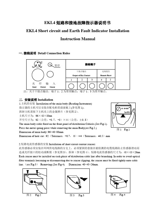
EKL4短路和接地故障指示器说明书EKL4 Short circuit and Earth Fault Indicator InstallationInstruction Manual一.接线说明Detail Connection Rules二. 安装说明Installation1.主机的安装Installation of the main body (Reading Instrument)指示器的主机可以安装在配电柜的前面板上(参见图1)。
拆卸主机需按下主机壳上的金属弹片(参见图2)。
主机尺寸为:96×48×80mm开空尺寸为:92(公差:+0.7,-0)×44(公差:±0.5)The main body cable fixed on the front panel of distribution Cubicle.(See Fig.1).Press the metal spring piece while removing the main Body(see Fig.2.)Dimension of main body: 96×48×80mmDimension of hole-cut : 92(Tolerance:+0.7,-0)×44(Tolerance:±0.5)mm2.短路电流传感器的安装Installation of short circuit current sensors此传感器必须安装在环网供电线路的分支上,必须紧固的套接在被检测的电缆线路防止传感器滑动而造成光纤接口的松动或断裂(参见图3)。
拆卸(参见图4)。
短路电流传感器的尺寸为:40×43×26mm Each sensor must be installed on each phase of distribution cable line after branching. In order to avoid optical fiber terminals loosening or disconnecting due to sensor slipping, the sensor must be fixed tightly onto cable line.(see Fig.3)Removing (See Fig.4) Dimension: 40×43×26mm.图2 Fig.2图1 Fig.1图3 Fig.33. 接地电流传感器的安装Installation of earth-fault current sensor 此传感器安装在三芯电缆上,此传感器的磁轭应将三根导线包围起 来(参见图5)。
欧克燃烧机中文说明书及故障代码

后吹扫时间 选择参数 758 输入关机后风机应保持的工作时间(秒),这时风门打 开。 故障停机无此功能。 标准设定 0 秒。 无后吹扫。
7
前吹扫风门延迟时间 选择参数 768 在“风机启动”后,风门将受到该设定值(秒)的延时, 如风机启动电流过大时,可降低耗电量。
故障后自动重新启动 参数 No.836
0 = 不启动* >1 = 重新启动(见故障代码 P)
= 在设定秒后重新启动 请根据燃烧系统需要设定该参数。
负荷控制装置 设定点输出 选择参数 No.796 和 798
(设定点 1 和设定点 2) 如果有环境天气控制,还要设定 797 和 799。
控制范围 选择设定参数 No.802 和 803
802 = 设定点向下差值 803 = 设定点向上差值 根据参数 809 的设定,输入为℃,bar 或数字信号。
设定控制传感器 选择参数 No.804 内容 = 与设定点的差值
(必须等于或大于参数 803)
控制参数
选择参数 No.805-808
(P,I,D,调整时间)
例:
值 805 = 4
806 = 3 807 = 100 808 = 控制线的间隔时间 秒
基本设定 输入密码 选择语言 输出通道 有或者没有引导火启动 预吹扫时间 重新循环延迟时间 未运行时,负荷控制装置 运行时,预设 DPS 负荷输入 最小组群运行时间 后吹扫时间 前吹扫风门延迟时间 接口参数 未运行时,泄漏检测 设定点火燃烧器 故障后自动启动 负荷控制装置设定点输入 控制范围 设定控制温控 控制参数 外部温度范围 负荷控制值显示装置 显示范围 bar 调整控制元件 进入曲线 消除记忆 点火点编程 基本负荷编程 储存曲线
FI-TEST-1故障指示器综合测试仪安装使用说明书

面板右侧的开关为高压开关,只有拨到“ON”时,高电压才能输出。
测试故障指示器操作顺序:
按“向上”、“向下”按键,使光标在“自动”、“手动”之间来回切换,选中相应的运行方式后,按“确认”按键,进入相应的界面。
“向左”、“向右”、“向上”、“向下”四个按键用来移动光标,当选定设置项目后,按“确认”按键,进入项目的数值设置,数值设置完毕,按“确认”退出数值设置;当光标指向“存
选择类型号,点击读取,将仪器FLASH中的数据读到缓存中;然后再选择要运行的项目号,点击读取,等待数据读取完毕后,点击运行开始运行数据。
使用后台中的数据,点击自动菜单,选择使用“使用后台数据”,界面如下图所示:
选择好测试类型,测试项目,点击运行,数据开始运行。
存储:存储功能是将后台中的数据存储到仪器中,存储操作会覆盖仪器中原有的数据。
界面如下图所示:
针对新的类型的指示器,后台数据口中没有相应的测试数据时,可通过导入辑好的数据,来增加新的故障指示器类型。
三、技术参数。
- 1、下载文档前请自行甄别文档内容的完整性,平台不提供额外的编辑、内容补充、找答案等附加服务。
- 2、"仅部分预览"的文档,不可在线预览部分如存在完整性等问题,可反馈申请退款(可完整预览的文档不适用该条件!)。
- 3、如文档侵犯您的权益,请联系客服反馈,我们会尽快为您处理(人工客服工作时间:9:00-18:30)。
产品简介:
EKL1 系列架空型故障指示器安装在 6 - 35KV 输配电线路上,用于指示故障电流流通的装置。
线路发生故障,巡线人员可借助指示器的红色报警显示迅速确定故障区段并找出故障点。
极大地提高了工作效率、缩短停电时间,有效地提高了供电的可靠性。
本公司依托清华大学的科研优势,在总结已有的故障检测装置的基础上,提出一种全新的故障检测方法,并申报国家发明专利,故障检测装置检测方法新颖,不仅动作可靠、性能稳定,而且安装和卸落都极其简单方便。
产品特点:
故障指示:正常运行时,窗口为白色显示;发生短路、接地故障时,窗口为红色显示
在线运行:直接安装在架空线路上,免维护。
抗干扰强:信号不受线路、励磁涌流、高次谐波、电流波动,尤其是电缆分布电容分路的影响
自动复位:指示器动作翻牌后,按设定时间自动复位。
带电装卸:带电装卸极其简单,不影响线路运行。
适用线路
◆用于 6 - 35KV 架空裸导线、绝缘导线
◆专用于 6 - 35KV 电缆线路
安装位置
安装在长线路的中段和分支入口处:可指示线路故障区段及故障分支。
安装在变电站出口:可判明是站内或站外故障。
安装在用户配变高压进线处:可判明故障是否由用户原因造成。
安装在电缆与架空线连接处:可区分故障是否在电缆段。