齐大山GE788FS10备件手册
50T支架搬运车备件手册
50T支架搬运车备件手册部件目录1(总体布置2(LWC50T前铰接装置 3(铰接装置4(LWC50T拖车装置 5(CAT3126柴油发动机组件第一部分总体布置1(LWC50T总体布置 7-220280-700备件清单 1页图号: 7-220280-700 LWC50T支架搬运车修改版本: 修改者:DA 批准日期:2002.10.29计数序号图号修改版本名称数量单位 1 7-220336-700 前铰接装置件 1 2 7-060485-700 铰接装置件 1 3 7-220337-700 拖车组件件 1第二部分 LWC50T-前铰链部分1(前底盘组件 7-017351-700 , 水箱系统 7-052671-700 , 燃油箱系统 7-052664-700 , 挡泥板和夹紧座 7-016273-7002(从动桥装置 7-041606-700 , LWC50T前轮装置 7-041728-7003(变速箱组件 7-041902-700 , 泵飞轮连接件装置 7-041746-700 , 泵组 7-073381-700 , 泵备件 7-073122-700 , 泵备件 7-073123-700 , 传输胶管装置 7-073152-700 , 泵吸入口胶管组件 7-073198-7004(柴油机系统总成 7-052658-700 , 柴油机底床架装置 7-016841-700 , 燃油关闭装置 7-052232-700 , 排气系统总成 7-052659-700 , 排气管冷却水泵组件7-052831-700 , 排气调节装置 7-052161-700 , 冷却系统总成 7-052660-700 , 热交换器装置 7-052193-700 , 热交换器胶管装置 7-052131-700 , 多页风扇装置7-052804-700 , 柴油机系统附件总成 7-052661-700 , 起动马达 7-160516-700, 气动阀安装组件 7-160493-700 , 储气罐装配装置 7-160491-700 , 油门调节器装置 7-052314-700 , 转速器转动装置 7-052784-700 , 补油缸装置 7-130129-700 , 遥控滤油器装置 7-052440-700, 柴油机呼吸器 7-052779-700 , 进气系统总成 7-052827-700 , 空气过滤器装置 7-052285-700 , 空气滤清器 7-051679-700 , 进气关闭装置 7-052828-700 , 压气软管 7-160507-700, 柴油机系统安全回路 7-160494-7005(电气系统底架 7-081903-700 , ATF前灯 7-081607-700 , ATF 351系列开关壳体 7-081876-700 , 变流发电机装置 7-081985-7006(驾驶室总装 7-121182-700 , 方向盘组件 7-121153-700 , 驾驶室车门装置7-017608-700, 液压控制总管组件 7-073263-700 , 主仪表盘装置 7-121158-700 , 侧边仪表盘装置 7-121183-700 , 座椅 7-121086-700 , 风门和制动踏板装置 7-121130-700 , 气喇叭组件 7-181701-704 , 联锁变速杆装置 7-160512-700 , 车辆控制管7-073778-700 , 压力测量管 7-073779-700第二部分:LWC50T-前铰链部分1.前底盘组件 7-017351-700 , 水箱系统 7-052671-700 , 燃油箱系统 7-052664-700 , 挡泥板和夹紧座 7-016273-700备件清单 1页图号: 7-017351-700 前底盘组件修改版本: 修改者:RCS 批准日期:2004.9.20计数序号图号修改版本名称数量单位 1 7-017346-700 C 底盘焊接件件1 2 7-160513-700 球阀总管件 1 3 7-016273-700 挡泥板铰链和夹紧座件 2 4 7-016412-700 A 油地槽护板件 1 5 7-017356-700 D 仪表盖板件 1 6 7-016854-700 C 格栅件 1 7 7-015323-704 B boart longyear标志件 2 8 7-016858-700 A 储气罐护板件 1 9 7-052664-700 燃油箱组件件 1 10 7-016873-700 E 盖板支架件 1 11 7-016957-700 A 控制盘 1 件 1 12 7-052671-700 水箱组件件 1 13 7-016915-700 洗涤器盖件 1 14 7-016924-700 起动马达盖件 1 15 7-016958-700 控制盘 2 件 1 16 7-190362-700 加油口铭牌件 1 17 7-016981-700 温度转换器面板件 1 18 HHM10X55X1.5P 六角螺栓M10X55长件 2 19 7-017049-700 手摆泵液管安装架件 1 20 HHM20X55X2.5P 六角头螺栓M20X55长件 8 21 HHM16X80X2P 六角头螺栓M16X80长件 6 22 HHM12X25X1.75P 六角螺栓M12X25长件 6 23 HHM20NUT 六角螺母M20 件 8 24 HHM20FW 平垫圈M20 件 8 25 HHM16FW 平垫圈M16 件 6 26 HHM10FW 平垫圈M10 件 42 27 HHM12FW 平垫圈M12 件 6 28 HHM12X30X1.75P 六角螺栓M12X30长件 10 29 HHM10X25X1.5P 六角螺栓M10X25长件 42 30 HHM8X20X1.25P 六角头螺栓M8X20长件 7 31HHM10X30X1.5P 六角头螺栓M10X30长件 5备件清单 1页图号: 7-052671-700 水箱组件修改版本修改者:CC 批准日期:2004.10.21计数序号图号修改版本名称数量单位件 1 7-181025-702 柴油机水箱弹簧盖 1 2 7-052669-700 水箱盖件 1件 3 HHM16X60X2P 六角螺栓 M16X60 长 6件 4 HHM10X30X1.5P 螺栓 M10X30 长ZN 20 5 7-072125-702 DUBBO垫圈3/8 件 20件 6 CB4-1216 尾管 1件 7 7-050517-700 B 燃油长筒过滤器 1 8 P-PLUG3/4BSPT BSPT压力螺堵3/4 件 1件 9 7-052670-700 水箱密封垫 1件 10 7-052666-700 水箱焊接件 1 11 7-050433-700 M 流量控制阀(LWC cutout) 件 1件 12 7-190373-700 水箱铭牌 1件 13 HHM6X16X1P 六角螺栓M6X16长 4备件清单 1页图号: 7-052664-700 燃油箱组件修改版本: 修改者:CC 批准日期:2004.10.06计数序号图号修改版本名称数量单位件 1 HHM10X25X1.5P 六角螺栓M10X25长zn 16 2 7-072125-702 DUBBO垫圈3/8 件 18件 3 SKM6X20 套头螺栓 4件 4 7-181025-702 柴油机油箱弹性盖 1 5 7-050517-700 B 燃油长筒过滤器件 1件 6 7-190372-700 燃油箱铭牌 1件 7 7-052657-700 燃油箱密封垫 1 8 7-052656-700 燃油箱盖件 1件 9 7-052655-700 D 燃油箱铰接件 1件 10 P-PLUG3/4BSPT 压力堵塞3/4 BSPT 1 11 7-016982-700 A 水箱门闩件1件 12 NUTNYLOCM12 尼龙螺母M12X1.75P 1件 13 L4421000 把手 1 14 HHM12FW 平垫圈M12 件 1件 15 HHM12SW M12弹性垫圈 1件 16 7-017374-700 燃油箱铰链销 1 17 7-017375-700 燃油箱铰链件 1 件 18 7-181171-703 窥镜 1备件清单 1页图号: 7-016273-700 挡泥板和夹紧座修改版本: 修改者:DBA 批准日期:1999.3.25计数序号图号修改版本名称数量单位件 1 7-016273-701 挡泥板 12 7-016273-702 挡泥板夹杆件 1第二部分:LWC50T-前铰接部分2(从动桥装置 7-041606-700, LWC50T前轮装置 7-041728-700备件清单 1页图号: 7-041606-700 从动桥装置修改版本: A 修改者:DBA 批准日期:1999.1.14计数序号图号修改版本名称数量单位 1 NUTNYLOC3/4NC 尼龙螺母3/4UNC 件 8 2 7-180110-730 轴承锁紧螺母件 4 3 7-180111-730 锁紧垫圈件 2 4 7-041248-700 舌型垫片件 2 5 HH12X2NC 六角螺栓3/4 件 24 6 7-041728-700 前轮件 2 7 HH12X10NC 六角螺栓3/4 件 8 8 7-041103-700 C 桥体件 1 9 7-180202-733 桥面密封件 2 10 7-041356-700 轮毂件 2 11 SK6X1NC 套头螺栓3/8 件 8 12 SK8X1NC 套头螺栓1/2 件8 13 HH8SW 1/2’’弹性垫圈件 8 147-041207-700 螺母件 2 15 7-041242-700 轴件 2 16 7-041208-700 键件 2 17 7-041128-700 C 防尘盖件 2 18 7-180103-729 圆锥滚子轴承件 2 19 7-041205-700 A 轴承座件 2 20 7-041371-700 车轮螺栓件 16 21 7-041368-700 车轮螺母件 16 22 7-041243-700 B 前轮轴承座件 2 23 7-180103-730 圆锥滚子轴承件 2 24 HH12X51/2NC 六角螺栓3/4” 件8 25 HH12NUT 3/4”UNC螺母件8 26 HH12SW 3/4”弹性垫圈件 8 27 7-190369-700 前桥注滑脂点铭牌件 2 28 7-073282-063 胶管装置件 2 29 7-017061-700 轴返回集管件 1 30 7-017122-700 轴T型分流器件 1 31 CB2-1217 接头件 1 32 CN56-1217 弯管件2 33 C64-171717 三通管件 1 34 C84-1714B 连接装置件 1 35 C46-1414 弯管件 1 36 HHM10X20X1.5P 六角头螺栓M10X20长ZN 件 2 37 HHM10SW 弹性垫圈M10 件 2备件清单 1页图号: 7-041728-700 前轮组件修改版本: 修改者:RCS 批准日期:2002.5.29计数序号图号修改版本名称数量单位件 1 7-041357-700 A 新型前轮辋 1 2 7-181301-728 轮胎件 1千克 3 7-181302-717 轮胎填充物 270第二部分:LWC50T-前铰接部分3(传输装置 7-041902-700 , 泵和飞轮连接装置 7-041746-700 , 泵组 7-073381-700 , 泵备件 7-073122-700 , 泵备件 7-073123-700, 传输胶管组件 7-073152-700 , 泵吸入胶管组件 7-073198-700备件清单 1页图号: 7-041902-700 传输装置修改版本: 修改者:RCS 批准日期:2004.12.21计数序号图号修改版本名称数量单位件 1 7-041746-700 泵飞轮连接装置 1 2 7-073381-700 泵组件 1件 3 7-073152-700 B 传输胶管组件 1件 4 7-190362-700 液压油注油口铭牌 1 5 7-070944-700 摆动泵件 1件 6 7-072771-700 单向阀 1备件清单 1页图号: 7-041746-700 泵飞轮连接装置修改版本: 修改者:RCS 批准日期:2003.1.23计数序号图号修改版本名称数量单位件 1 7-052332-700 柴油机壳体连接件 1 2 7-052333-700 连接齿轮横向加紧锁件 1件 3 7-052334-700 钢质传动板 1件 4 SKM10X30X1.5P 螺钉M10X30长 8 5 NUTNYLOCM10 尼龙螺母M10X1.5P 件8件 6 HH6X11/4NC 六角螺栓3/8” 12件 7 P-PLUG3/8NPT 压力堵塞3/8”NPT 4 8 HH5X11/4NF 5/16”UNF X 1-1/4”长件 12备件清单 1页图号: 7-073381-700 泵组修改版本: 修改者:RSC 批准日期:2004.12.21计数序号图号修改版本名称数量单位件 1 7-073122-700 A 闭合回路泵1 1 2 7-073123-700 P 闭合回路泵2 件 1 件 3 7-073151-700 载荷传感变量泵 1件 4 HH12X12/4NC 六角螺栓3/4” 2 5 HH12FW 平垫圈3/4” 件 2件 6 SKM12X30X1.75P 螺钉 M12X30长 2件 7 HHM12FW 平垫圈M12 27-073294-700 测试耦合件 4备件清单 1页图号: 7-073122-700 闭合回路泵1修改版本:A 修改者:RCS 批准日期:2003.1.29计数序号图号修改版本名称数量单位件 7-073182-700 滤网 17-073295-700 加压泵 A4VG..F69 件 1件 7-073297-700 主安全阀 1件 7-073298-700 增压安全阀 17-073299-700 旋转组件件 1件 7-073300-700 支架轴承组件 1件 7-073301-700 前轴承 17-073302-700 后轴衬件 1件 7-073303-700 盘形弹簧 1件 7-073304-700 晶状体板-右侧 17-073305-700 旋转部件件 1件 7-073306-700 回油口+六角螺母 1件 7-073307-700 控制密封垫 HW 17-073308-700 控制密封垫 EP/HD 件 1件 7-073309-700 密封元件 1件 7-073310-700 轴密封橡胶N 17-073311-700 密封件件 1件 7-073312-700 轴密封-VITON 1备件清单 1页图号: 7-073123-700 闭合回路泵2修改版本:P 修改者:RCS 批准日期:2003.1.29 计数序号图号修改版本名称数量单位件 7-073182-700 滤网 17-073296-700 加压泵 A4VG..F02 件 1件 7-073297-700 主安全阀 1件 7-073298-700 增压安全阀 17-073299-700 旋转组件件 1件 7-073300-700 支架轴承组件 1件 7-073301-700 前轴承 17-073302-700 后轴衬件 1件 7-073303-700 盘形弹簧 1件 7-073304-700 晶状体板-右侧 17-073305-700 进油口-PRE99 件 1件 7-073306-700 回油口+六角螺母 1件 7-073307-700 控制密封垫 HW 17-073308-700 控制密封垫 EP/HD 件 1件 7-073309-700 密封元件 1件 7-073310-700 轴密封橡胶N 17-073311-700 密封元件件 1件 7-073312-700 轴密封-VITON 1备件清单 1页图号: 7-073152-700 传输胶管装置修改版本 :C 修改者:RCS 批准日期:2003.2.04计数序号图号修改版本名称数量单位件 1 7-073198-700 A 胶管组件 1 2 7-073209-700 司机侧回路回油胶管总成件 1件 3 7-073210-700 司机侧回路进油胶管总成 1司机另一侧回路回油胶管总件 4 7-073211-700 1 成司机另一侧回路进油胶管总件 5 7-073212-700 1 成件 6 7-180203-855 O形圈(配合SAE法兰) 0件 7 7-180501-715 1-1/4”SAE加紧组件 8备件清单 1页图号: 7-073198-700 泵吸入口胶管装置修改版本:A 修改者:DA 批准日期:2003.4.16计数序号图号修改版本名称数量单位件 1 7-073289-700 改造的螺堵 1 2 3301-3232 2”BSPT×2”胶管接头件 2件 3 7-182208-765 温度/关闭阀 1件 4 3340-3224 90?弯头1-1/2”BSPT 1 5 CB63-242424 内接三通1-1/2”BSPT 件 1两端外接头1-5/8”活结头6 M7-4826 件 2 连接7 MB-48 BONDED垫圈48MM 件 290?弯头内接头对外接头-件 8 CB55-2424 1 内接头对外接头件 9 7-073269-700 改造接头 1件 10 RSC-6368 胶夹管63-68MM范围 6内螺纹接头1-5/8”活接头件 11 S61-2426 2 连接件 12 3301-3224 1-1/2”BSP-2”胶管嵌入件 1件 13 7-073234-065 胶管装置SR32-650 C/L 1件 14 RO-SF20 O形圈1-1/4” 1件 15 7-073234-200 胶管装置 1件 16 7-073234-230 胶管装置 1件 17 S40K-20 法兰夹 1套 FK61-20 7/16"螺栓组件 0第二部分:LWC50T-前铰接部分4(柴油机系统总成 7-052658-700 , 柴油机辅助架装置 7-016841-700 , 燃油切断装置 7-052232-700 , 排气系统总成 7-052659-700 , 排气水泵组件 7-052831-700 , 排气调节器装置 7-052161-700 , 冷却系统 7-052600-700 , 散热器装置 7-052193-700 , 热交换器胶管装置 7-052131-700 , 多叶风扇装置 7-052804-700 , 柴油机系统附件总成 7-052661-700 , 起动马达 7-160516-700 , 气动阀安装总成 7-160493-700 , 储气罐装置 7-160491-700 , 油门调节器装置 7-052314-700 , 转速器驱动装置 7-052784-700 , 充油筒装置 7-130129-700 , 遥控滤油器装置 7-052440-700 , 柴油机呼吸器 7-052779-700 , 进气系统总成 7-052827-700 , 空气过滤器装置 7-052285-700 , 空气滤清器 7-051679-700 , 进气关闭装置 7-052828-700 , 压气软管 7-160507-700, 柴油机系统安全回路 7-160494-700备件清单 1页图号: 7-052658-700 柴油机系统总成修改版本: 修改者:RCS 批准日期:2004.9.24计数序号图号修改版本名称数量单位件 1 7-052021-700 柴油发动机CAT3126 1 2 7-016841-700 A 柴油机底床架装置件 1件 3 7-052185-700 燃油总成CAT3126 1件 4 7-052659-700 排气系统总成 1 5 7-052660-700 冷却总成3126 件 1 件 6 7-052661-700 柴油机系统附件总成 1件 7 7-052827-700 进气总成 1备件清单 1页图号: 7-016841-700 柴油机底座框架装置修改版本:A 修改者:DA 批准日期:2003.2.21计数序号图号修改版本名称数量单位D 件 1 7-016874-700 柴油机底床架焊接件 1C 2 7-016875-700 前底座框架臂件 1C 件 3 7-016876-700 后底座框架臂 1A 件 4 7-016877-700 排气管支架 1 5 7-016878-700 反弹垫圈件 4件 6 7-016891-700 泵支架 1件 7 7-180711-707 隔震器 2 8 7-180711-708 隔震器件 2件 9 HHM24X180X3P 六角螺栓M24X180长ZN 4件 10 NUTNYLOCM24 尼龙螺母M24X3P 4 11 HHM16X65X2P 六角螺栓M24X180长ZN 件 8件 12 HHM16FW 平垫圈M16 8 13 HHM16SW 弹性垫圈M16 ZN 件 8 14HHM16X45X2P 六角螺栓M12X45长件 2件 15 HHM16NUT 六角螺母M16 ZN 2件 16 7-016959-700 柴油机安装垫圈 4 17 HHM10X45X1.5P 六角螺栓M10X45长件 16件 18 HHM10NUT 六角螺母M10 16件 19 HHM10SW 弹性垫圈M10 16备件清单 1页图号: 7-052232-700 燃油切断装置修改版本修改者:RCS 批准日期:2003.3.03计数序号图号修改版本名称数量单位件 1 7-052172-700 A 燃油切断装置套筒 1 2 7-052173-700 A 燃油控制圆盘件 1件 3 7-052241-701 O型密封圈 1件 4 7-180704-744 压力弹簧 1 5 7-182207-711 气缸件 1件 6 7-180606-710 1/8”烧结的呼吸器 1件 7 DB17/0207 弯头CB56-0207 1 8 SSS3X1/4NC 无锈螺钉DIA3/16X1/4长件 1备件清单 1页图号: 7-052659-700 排气系统总成修改版本: 修改者:RCS 批准日期:2004.9.24修改版计数序号图号名称数量本单位件 1 7-052145-700 F 水冷却消焰装置 1 2 7-052154-700 I 排气管(水冷) 件 1件 3 7-052155-700 B 盖—排气管 1件 4 7-052156-700 A 密封垫—排气管 1 5 7-052157-700 密封垫—排气管件 1件 6 7-052158-700 A 密封垫—排气管 1件 7 7-052159-700 密封垫—洗涤向外用接头 1 8 7-052161-700 洗涤箱总成件 1件 9 7-052304-700 改进型涡轮—排气 1件 10 7-052831-700 排水喷雾装置 1 11 7-073225-700 温度控制阀106C 件1件 12 7-180821-702 法兰螺母M10 4件 13 HHM16X50SS M16X50LG stainless HH 4 14 HHM16X40SS M16X50LG stainless HH 件 8件 15 HHM12X30SS M16X50LG stainless HH 8件 16 HHM12FWSS M12 无锈平垫圈 8 17 HHM12X30X1.75P 六角螺栓M12X13LG 件 4件 18 HHM12FW M12平垫圈 4件 19 7-180823-701 双头螺栓M10X60长 4 20 7-052785-700 温度控制阀150C 件 1件 21 7-052200-703 密封垫 1件 22 7-052200-702 密封垫 1 23 7-052122-701 密封垫—涡轮增压器件 1 件 7-181041-706 20升洗涤添加剂 1备件清单 1页图号: 7-052831-700 排水喷雾装置修改版本: 修改者:CC 批准日期:2005.5.30计数序号图号修改版本名称数量单位件 1 7-160188-702 调节器 1 2 7-160523-700 隔膜泵件 1件 3 7-182208-710 油/水防启动装置 1件 4 7-052329-700 F 喷嘴 1 5 7-073293-140 胶管装置件 1件 6 7-073283-130 胶管装置 1件 7 7-073282-050 胶管装置 1 8 S27-0202 接头件 1件 9 S74-0207 接头 2件 10 S76-0207 弯管 1 11 S15-1212 弯管件 2件 12 S7N-0812 接头 2件 13 S8N-0407 弯管 1 14 S7N-0412 接头件 1件 15 PS-18 通气装置 1件 16 S7-0814 接头 1备件清单 1页图号: 7-052161-700 洗涤箱组件修改版本修改者:DA 批准日期:2003.1.15计数序号图号修改版本名称数量单位件 1 7-052162-700 F 洗涤器焊接箱件 1 2 7-052167-700 检查盖件 1 件 3 7-052168-700 密封垫—检查盖 1件 4 7-052306-700 A 低水位关闭浮漂 1 5 7-052307-700 水位浮子阀件 1 件 6 7-073404-700 温度控制阀70 C 1件 7 7-180412-704 球阀1/2”316SS BSP 1 8 CN2-0814 接头件 1件 9 7-180966-703 不锈压力螺堵 1件 10 7-180966-704 1/2”BSPT 不锈螺堵 1 11 SK5X1/2NCSS 螺钉5/16”UNCX1/2”长件 4件 12 7-180412-725 球3/4”316SS(20MM) 1S.S.90DEG弯管内接头对内件 13 7-180967-706 1 接头件 14 7-180967-709 1/2”BSP 无锈弯管 1备件清单 1页图号: 7-052660-700 冷却系统总成3126修改版本: 修改者:RCS 批准日期::2004.9.24修改版计数序号图号名称数量本单位件 1 7-052131-700 冷却系统胶管装置 1 2 7-052193-700 散热器装置件 1 件 3 7-052804-700 风扇配有扇叶和毂 1件 4 7-052289-700 B 风扇连接装置 1 5 7-052676-700 A 上部水箱焊接件1件 6 7-181211-723 三角带A56 FRAS 2件 7 7-181014-712 卸压盖 1 8 7-181211-729 三角带 A33 FRAS 件 1件 9 HCLAMP2.5 夹紧教管 6件 10 HHM12X40X1.75P 六角螺栓M12X40长 4 11 HHM12FW M12平垫圈件 4 件 12 HHM12SW 弹性垫圈M12 4件 13 HHM8X65X1.25P 六角螺栓M8X65长 6 14 HHM8FW 平垫圈M8 件 6件 15 7-052751-700 风扇皮带轮垫片 1件 16 7-052343-700 改进型滑轮 1 17 7-052752-700 风扇皮带轮垫片件 1 件 18 7-182208-709 温度控制阀 103C 1件 19 7-052345-700 防松垫片 1 20 7-181041-702 CAT DEAC 20LIR 冷却液件 1件 21 7-190364-700 热交换器注入口标签 1件 22 HHM10HFW 硬的平垫圈 M10 2 23 HHM10X55X1.5P 六角螺栓M10X55长件 1件 24 HHM10X75X1.5P 六角螺栓M10X75长 1件 25 NUTNYLOCM10 尼龙螺母M10X1.5P 1 26 7-052177-711 密封垫—热交换器件 1备件清单 1页图号: 7-052193-700 热交换器装置修改版本: 修改者:RCS 批准日期:2003.2.05计数序号图号修改版本名称数量单位件 1 7-052299-700 热交换器 1 2 7-052300-700 油冷却器/风扇式件 1 件 3 7-052301-700 风扇外壳 1件 4 HH6X1NC 六角螺栓3/8 14 5 HH6FW 3/8”平垫圈件 14备件清单 1页图号: 7-052131-700 冷却系统胶管装置修改版本: 修改者:DA 批准日期:2002.8.27计数序号图号修改版本名称数量单位热交换器胶管(内径51X432件 1 7-052286-700 1 长)件 2 7-052311-700 热交换器顶管 1件 3 7-180306-747 90?弯曲胶管内径50 1 4 7-180306-748 输水胶管件 1 件 5 7-180501-705 2”胶管夹 6件 6 7-073286-127 胶管装置—T116D 1 7 7-073278-448 胶管装置件 2 件 8 7-073284-036 胶管装置 1件 9 7-073284-055 胶管装置 1备件清单 1页图号: 7-052804-700 风扇 C/W 叶片&ZN 毂修改版本: 修改者:SM 批准日期:2005.5.06计数序号图号修改版本名称数量单位件 1 7-052748-700 风扇毂镀锌 1 2 7-052749-700 定位销件 9件 3 7-052805-700 扇叶810MM DIA 9件 7-052804-100 风扇组件 1备件清单 1页图号: 7-052661-700 柴油机系统附件总成修改版本: 修改者:RCS 批准日期:2004.9.24计数序号图号修改版本名称数量单位件 1 7-017416-700 3126后吊钩 1 2 7-052174-700 加油隔离板件 1件 3 7-052247-701 管 1件 4 7-052314-700 油门调节器装置 1 5 7-130129-700 机油加压缸件 1 件 6 7-052564-700 水分离器托架 1件 7 7-160493-700 气动阀组件 1 8 7-160516-700 起动马达件 1件 9 7-160491-700 储气罐 1件 10 7-052440-700 遥控滤油器 1 11 7-052784-700 转速器驱动组件件 1 件 12 7-180412-722 3位球阀 2件 13 7-160022-700 冷却剂耗损支架 1 14 7-182208-725 冷却剂耗损阀件 1备件清单 1页图号: 7-160516-700 起动马达修改版本: 修改者:CC 批准日期:2004.5.07计数序号图号修改版本名称数量单位件 1 7-160344-702 继动阀MPV LWC S/C 1 2 7-160464-702 过滤器件 1 件 3 7-160486-700 起动马达 1件 4 7-180301-705 1”螺纹管 1 5 HHM10X30X1.5P 六角头螺母M10X30长ZN 件 3件 6 CN2-0207 接头 1件 7 C46-0707 90?弯管 1 8 CN56-0207 弯管件 1件 9 CN56-1621 弯管 1件 10 CN27-1621 直接头 1 11 CN2-0407 接头件 1件 12 CB2-1621 接头 1备件清单 1页图号: 7-160493-700 气动阀安装组件修改版本: 修改者:RCS 批准日期:2003.3.03计数序号图号修改版本名称数量单位件 1 7-120991-701 不锈钢标签 1 2 7-120991-702 不锈钢标签件 1件 3 7-120991-703 不锈钢标签 1件 4 7-120991-704 不锈钢标签 1 5 7-160445-700 A 分流器件 1件 6 7-160492-700 A 气动阀安装板 1件 7 7-160514-700 安全回路接头 1 8 7-182208-710 油/水防起动阀件 3件 9 7-182208-727 流量控制阀 2件 10 7-182208-773 小型提升阀 1 11 7-160469-700 气动分流块件 1备件清单 1页图号: 7-160491-700 储气罐装备修改版本: 修改者:RCS 批准日期:2003.3.03计数序号图号修改版本名称数量单位件 1 7-160153-700 聚四氟乙烯编制软管 1 2 7-160310-700 B 储气罐件 1 件 3 7-180412-715 3/8 球阀 2件 4 7-182208-702 主气罐安全阀 1 5 7-182208-704 单向阀件 1件 6 7-181206-747 RS高强度系列滚子链 2件 7 7-181206-748 连接环3/4”节距 4 8 7-181239-719 拉杆和连接块件 2 件 9 HHM10X50X1.5P 六角头螺栓M10X50长ZN 2件 10 HHM10NUT 六角螺母M10 2 11 HHM10FW 平垫圈 M12 件 2件 12 HHM10SW 弹性垫圈M10 22 件 13 7-014478-702 储气罐挂钩14 7-180502-716 1”进气接头件 1件 15 CN66-040404 三通管 1件 16 CN38-0407 45?接头 1 17 CB54-0808 弯管件 1件 18 CN2-0812 接头 1件 19 CB56-1221 弯管 1 20 CB56-0609 弯管件 1件 21 CB56-0812 弯管 1件 22 CB56-0814 弯管 1 23 CB73-0806 减压器件 1件 24 CB62-060606 三通管 1件 25 CB38-0609 45?接头 1 26 HHM8X50X1.25P 六角头螺栓M8X50长件 2 件 27 HHM8NUT 螺母M8 2件 28 7-190368-700 充气/排气标签 1备件清单 1页图号: 7-052314-700 油门调节装置修改版本: 修改者:RCS 批准版本2003.4.15计数序号图号修改版本名称数量单位件 1 7-052313-700 C 油门气缸支架 1 2 7-160317-700 油门气缸件 1件 3 7-180109-701 球形端杆 2件 4 7-052314-704 螺纹杆1/4”UNF 1 5 D15/0407 接头CN2-0407 件 1 件 6 HH4X1NC 六角头螺栓1/4 2件7 HH4FW 1/4”平垫圈 2 8 HH4NUT 1/4”UNC六角螺母件 2件 9 HHM6X25X1P 六角头螺栓M6X25长 4件 10 HHM6FW 平垫圈M6 ZN 4 11 HHM6SW 弹性垫圈M6 件 2件 12 HHM6NUT 六角螺母M6X1P 2件 13 HH4NUTNF 六角螺母1/4”UNF 2备件清单 1页图号: 7-052784-700 转速轮转动装置修改版本: 修改者:SM 批准日期:2005.4.18计数序号图号修改版本名称数量单位件 1 7-052240-702 密封垫 1 2 7-052690-700 服务表件 1件 3 7-052693-700 转速轮传动O形圈 1件 4 7-052695-700 转速轮传动夹片 2 5 7-052761-700 A 转速轮传动安装板件 1件 6 7-052762-700 转速轮传动连接板 1件 7 7-052763-700 转速轮传动垫片 1 8 7-052764-700 A 转速轮传动轴件1件 9 7-180105-700 球轴承 2件 10 7-180801-700 簧环直径25X1.3W 1 11 SKM10X20X1.5P 凹头有帽螺钉M10X20长件 2件 12 SKM6X16X1P 凹头有帽螺钉M6X16长 6备件清单 1页图号: 7-130129-700 机油加压缸修改版本: 修改者:RCS 批准日期:2003.3.03计数序号图号修改版本名称数量单位1 件 1 7-130128-700 柴油机吸油管2 2 7-181132-712 单向阀件1 件 3 7-182207-712 启动泵2 件 4 CN2-0407 接头5 CN56-0407 弯管件 1件 6 CN62-040404 三通管 1件 7 CN54-0404 弯管 1备件清单 1页图号: 7-052440-700 远程机油加油组件修改版本: 修改者:RCS 批准日期:2003.6.26计数序号图号修改版本名称数量单位件 1 7-052440-701 底座 1 2 7-052440-702 O型密封圈内径32.9MM 件 1 件 3 7-052440-703 滤油器底座 1件 4 7-052440-704 底座 1 5 7-052440-705 连接件件 1件 6 7-052440-706 弯头 1件 7 7-052440-707 弯头1 1/16-12STR THD 1 8 7-052440-708 管接头件 1 件 9 7-052440-709 密封O型圈 1件 10 7-052440-710 阻塞螺母 1 11 7-052440-711 接头件 1件 12 7-052440-712 柴油机滤油器 18 件 13 7-052440-713 垫圈8 14 7-052440-714 螺栓 3/8-16X1.25” 件件 15 7-052440-715 空心螺栓 1件 16 7-052440-716 密封O形圈 2 17 7-052440-717 弯头件 1件 18 7-052440-718 密封圈 2件 19 7-052440-719 密封垫 2 20 7-073286-210 胶管装置件 1件 21 7-073285-210 胶管装置 1备件清单 1页图号: 7-052779-700 柴油机通气设备修改版本: 修改者:PWK 批准日期:2005.4.15计数序号图号修改版本名称数量单位件 1 7-050475-700 A 通气装置 1 2 7-052776-700 A 黄铜过滤网件 5件 3 7-052778-700 固定板通气装置 1件 4 7-052100-702 密封O形圈 1 5 7-052100-704 垫圈(2MM厚) 件 1件 6 HHM8X50X1.25P 六角头螺栓M8X50长 1件 7 7-052780-700 粗钢棉 1备件清单 1页图号: 7-052827-700 进气系统修改版本: 修改者:SM 批准日期:2005.5.20计数序号图号修改版本名称数量单位件 1 7-052169-700 H 消焰装置—入口 1 2 7-052170-700 C 入口总管件 1 件 3 7-052277-700 90?橡胶弯头 1件 4 7-052278-700 波纹形变径管 1 5 7-052279-700 90?橡胶弯管件 1件 6 7-052822-700 进气管—短 1件 7 7-052281-700 入口连接管 1 8 7-052282-700 螺栓夹紧管箍SS4” 件 2 件 9 7-052283-700 螺栓夹紧管箍SS5” 1件 10 7-052284-700 螺栓夹紧管箍SS6” 3 11 7-052285-700 空气过滤器件1件 12 7-052297-700 排气管夹紧箍5” 1件 13 7-052305-700 进气涡轮—改进型 1 14 7-052828-700 B 中间冷却型改进器件 1件 15 7-052828-700 进气切断装置 1件 16 7-052823-700 进气管—长 1 17 7-016917-700 进气管安装座2 件 1 件 18 7-052220-702 密封垫 2件 19 HHM10FW 平垫圈M10 4 20 HHM10X30X1.5P 六角头螺栓M10X30长ZN 件4件 21 HHM10SW 弹性垫圈M10 6件 22 HHM10NUT 六角螺母M10 4 23 HHM10X25X1.5P 六角头螺栓M10X25长件4件 24 7-052115-704 改进型进气密封垫 1件 25 7-052219-701 摇杆盖密封垫 17-160507-700 进气胶管件 1备件清单 1页图号: 7-052285-700 空气过滤器修改版本: 修改者:CC 批准日期:2003.2.25计数序号图号修改版本名称数量单位件 1 7-051679-700 空气滤清器组件 1 2 7-051680-700 进气口盖件 1件 3 7-051681-700 安装带 2件 4 7-052276-700 工作指示原件 1备件清单 1页图号: 7-051679-700 空气滤清器修改版本: 修改者:DBA 批准日期:1998.8.24计数序号图号修改版本名称数量单位件 1 7-051679-701 一次性滤芯 1 2 7-051679-702 安全滤芯件 1件 3 7-051679-703 蝶形螺母 1件 4 7-051679-704 密封圈 1 5 7-051679-705 杯形夹件 1件 6 7-051679-706 密封圈 1件 7 7-051679-707 挡板组件 1 8 7-051679-708 水平真空杯件 1件 9 7-051679-709 真空阀 1备件清单 1页图号: 7-052828-700 进气切断装置修改版本: 修改者:SM 批准日期:2005.5.20计数序号图号修改版本名称数量单位件 1 7-052814-700 入口切断阀 1 2 7-052826-700 胶管flex fab 4 ply5”ID 件 2件 3 7-180514-708 紧固夹121-143MM C/TORQUE 4件 4 7-052297-700 排气管夹紧箍 2 5 7-016916-700 右进气管MTG BKT 件 1 件 6 7-017599-700 左进气管MTG BKT 1件 7 HHM10HFW 硬平垫圈 M10 4 8 HHM10NUT 六角螺母M10 件 4件 9 HHM10X20X1.5P 六角螺栓M10X20长ZN 4件 10 HHM10SW 弹性垫圈M10 4 11 HHM10FW 平垫圈M10 件 4备件清单 1页图号: 7-160507-700 通气胶管装置修改版本: 修改者:CC 批准日期:2004.2.09计数序号图号修改版本名称数量单位件 1 7-073283-100 胶管装置 1 2 7-073286-043 胶管装置件 1件 3 7-073286-063 胶管装置 1件 4 7-073286-080 胶管装置 1 5 7-073287-074 胶管装置件 1备件清单 1页图号: 7-160494-700 安全回路修改版本:B 修改者:DA 批准日期:2003.3.14计数序号图号修改版本名称数量单位件 1 7-160445-700 A 浮置总管 1 2 7-182208-745 起动按钮阀件 1件 3 7-181804-722 机油压力表 1件 4 7-182208-725 冷却剂耗损阀 2 5 7-073225-700 温度控制阀106C 件 1 件 6 7-073226-700 温度控制阀77C 1件 7 7-182208-709 温度控制阀103C 1 8 7-182208-703 来气切断球阀件 1 件 9 7-160334-702 继动阀 MPV LWCS/C 1件 10 7-160486-700 起动马达 1 11 7-160188-701 过滤器件 1件 12 7-160188-703 注油器 1件 13 7-181804-725 空气制动闸压力计 1 14 7-182208-746 杠杆式制动阀件 1件 15 7-181132-712 单向阀 2件 16 7-182207-712 启动泵 1 17 7-180412-722 KITZ3通球阀件 3件 18 7-180704-744 压力弹簧 1件 19 7-182207-711 气缸 1 20 7-182208-767 眼球式指示器件 1件 21 7-090831-700 弹簧作用制动器 1件 22 7-182208-773 小型提升阀 1 23 7-050433-700 M 浮球式阀件 1件 24 7-182208-727 流量控制阀 2件 25 7-160397-700 节流孔 0.8MM 2 26 7-182208-710 水/油防起动装置件 3件 27 7-052306-700 A 低水位切断浮子 1件 28 7-182208-765 温度/切断阀 1 29 7-052785-800 温度控制阀150C 件 1 第二部分:LWC50T-前铰接部分4(电气系统底架 7-081885-700, ATF前灯装置 7-081607-700, ATF351系列开关箱 7-081876-700, 交流发电机装置 7-081985-700备件清单 1页图号: 7-081903-700 电气系统修改版本: 修改者:RCS 批准日期:2004.9.24计数序号图号修改版本名称数量单位ATF头灯C/W红色发光二级件 1 7-081607-700 2 管件 2 7-081985-700 交流发电机装置 1件 3 7-081875-700 配电盒170C/W 6 X 1 4 7-081876-700 A 开关外壳件 1 件 5 7-081889-700 右侧密封管 1件 6 7-081890-700 20MM螺堵FLP 2 7 7-203915-703 压缩密封件 9件 8 7-081906-700 车载甲烷探测器系统 1件 9 7-081905-700 螺堵 1 10 7-081908-700 套节M20 件 12 米 7-081698-700 电缆4CX1.5mm1型 40米 7-203200-702 电缆管内径16MM FRAS 40备件清单 1页图号: 7-081607-700 ATF前灯C/W红色发光二极管修改版本: 修改者:KMG 批准日期:1998.1.18计数序号图号修改版本名称数量单位件 1 7-081607-701 固定环 1 2 7-081607-702 挡热透镜件 1件 3 7-081607-703 壳体 1件 4 7-081607-704 镜头盒 1 5 7-081607-705 O形圈件 1件 6 7-081607-706 螺栓 2件 7 7-081607-707 透镜护板 1 8 7-081890-700 螺堵20mm 件 1 件 9 7-201400-720 散光灯50W QH 40DGE 1件 10 7-201500-715 灯座C/红色发光二极管 1备件清单 1页图号: 7-081876-700 开关外壳修改版本: A 修改者:CC 批准日期:2003.4.10计数序号图号修改版本名称数量单位件 1 7-081876-701 A 开关K&N 1 2 7-081876-702 A 操作轴件 1 件 3 7-081876-703 A 开关 1件 4 7-081890-700 螺堵20mm 1 5 7-081876-705 A 壳体件 1件 6 7-081876-706 A 改进型盖 1件 7 7-081876-707 A 标签 1 8 7-081876-708 A 螺栓件 4备件清单 1页图号: 7-081985-700 交流发电机装置修改版本: 修改者:CC 批准日期:2005.2.25计数序号图号修改版本名称数量单位件 1 7-081987-700 B 交流发电机安装架 1 2 HHM16X50X2.0P 六角螺栓M16X50长ZN 件 2件 3 HHM16HFW 硬平垫圈M10 2件 4 7-081988-700 A 交流发电机调节架 1 5 HHM10X40X1.5P 六角螺栓ZN 件1件 6 HHM10HFW 硬平垫圈M10 3件 7 NUTNYLOCM10 尼龙螺母M10X1.5P 2 8 7-081997-700 A 交流发电机安装架件 1件 9 SKM8X16X1.25P 螺钉 M8X16长 4件 10 SKSSM12X90 螺纹SKSS M12X90长XM10 1 11 7-200207-700 交流发电机件 1件 12 7-181211-733 V”形A55/A1430FRAS 1第二部分:LWC50T-前铰接部分6(驾驶室总装 7-121182-700 , 方向盘组件 7-121153-700 , 驾驶室门 7-017608-700 , 液压控制总管路组件 7-073263-700 , 主仪表盘装置 7-121158-700 , 侧仪表盘装置 7-121183-700 , 井下司机座椅装置 7-121086-700 , 气门和制动踏板装置 7-121130-700 , 气喇叭 7-181701-704 , 变速互锁组件 7-160512-700, 车辆控制胶管 7-073778-700 , 压力表胶管 7-073779-700备件清单 1页图号: 7-121182-700 驾驶室总装修改版本: 修改者:RCS 批准日期:2004.9.24计数序号图号修改版本名称数量单位件 1 7-190377-700 前进/空挡/后退 1 2 7-190361-700 司机检查铭牌件 1 件 3 7-190363-700 A 风阀开/关标签 1件 4 7-190366-700 警告标签 2 5 7-190367-700 喇叭标签件 1件 6 7-190371-700 停车标签 1件 7 7-190370-700 紧急制动标签 1 8 7-190376-700 启动说明标签件 1 件 9 7-121153-700 驾驶盘组件 1件 10 7-017608-700 驾驶室门 1 11 7-073192-700 先导控制阀主件件 1 件 12 7-073224-700 液压操作气动阀 1件 13 7-090831-700 弹簧制动阀 1 14 7-090861-700 红色按钮(停车制动)件 1件 15 7-182208-813 阀 1件 16 7-121183-700 侧边仪表盘装置 1 17 7-121086-700 座椅件 1件 18 7-182208-813 滑阀 2件 19 7-121130-700 风门踏板 1 20 7-121158-700 主仪表盘装置件 1件 21 7-016857-700 A 风门踏板安装装置 1件 22 7-190356-700 压力释放铭牌 1 23 7-190359-700 辅助压力铭牌件 1 件 24 7-182208-703 断气球阀 1件 25 7-190355-700 马达排量铭牌 1 26 7-160188-701 过滤器件 1件 27 7-160188-703 注油器 1件 28 7-160452-700 空气总管 1 29 7-016922-700 座位安装隔离架件 2 备件清单 2页图号: 7-121182-700 驾驶室总装修改版本: 修改者:RCS 批准日期:2004.9.24计数序号图号修改版本名称数量单位件 30 7-160512-700 变速互锁装置 1 31 7-181701-704 气喇叭件 1件 32 7-181804-730 压力表0-250BAR 1件 33 7-181804-735 压力表0-40BAR 3 34 7-190374-700 听力保护铭牌件 1件 35 7-190357-700 增压铭牌 1件 36 7-190360-700 机器铭牌 1 37 7-072481-700 A 蓄能器 2.25L 件 1 件 38 7-073399-700 蓄能器支架 1件 39 7-073359-700 控制总管 1 40 7-181502-703 灭火器9KG 件 1件 41 7-181502-704 灭火器支架MTG 1件 7-073778-700 车辆控制软管 17-073779-700 压力表胶管件 1件 7-182208-726 梭形阀 1件 7-182208-727 流量控制阀 4备件清单 1页图号: 7-121153-700 驾驶盘组件修改版本: 修改者:CC 批准日期:2003.7.17计数序号图号修改版本名称数量单位件 1 7-121128-700 驾驶盘 1 2 7-180816-701 驾驶盘螺母件 1件 3 7-120460-700 方向盘“眼球式”套筒 1件 4 7-072769-700 眼球式转向阀 1 5 HH6X11/4NC 六角头螺栓3/8 件 2 件 6 HH6X3/4NC 六角螺栓3/8”UNCX3/4” 2件7 HH6SW 3/8”UNC 弹性垫圈 4备件清单 1页图号: 7-017608-700 驾驶室门修改版本: 修改者:CC 批准日期:2005.6.17计数序号图号修改版本名称数量单位件 1 7-017607-700 驾驶室门铰链 1 2 7-012969-700 A 固定板件 1件 3 7-012968-700 A 铰链销 1件 4 ROLLPIN3/16X11/4 销子DIA3/16X1-1/4长 1 5 7-012967-700 A 铰链件 1件 6 7-012964-700 A 门闩 1件 7 ROLLPIN3/16X21/2 销子DIA3/16X2-1/2长 1 8 7-012965-700 A 门闩销件 1件 9 ROLLPIN1/8X1 销子 DIA1/8X1长 2件 10 7-012987-700 拉簧 1 11 ROLLPIN3/16X13/8 销子DIA3/16X1-3/8长件 1件 12 HH10X11/2NC 六角头螺栓5/8 3件 13 HH10SW 弹性垫圈5/8” 3 14 L4421000 LEE-NORSE把手件 1件 15 7-012966-700 A 双头螺栓 1备件清单 1页图号: 7-073359-700 改进型控制装置修改版本: 修改者:RCS 批准日期:2004.10.18计数序号图号修改版本名称数量单位件 1 7-072871-700 测压点 11 2 7-073338-700 DCV CTOP3 MANUAL SPRING 件 1件 3 7-073358-700 控制总管 1件 4 7-073369-700 6号总管 1 5 7-073360-700 气动阀组件 1件 6 7-073361-700 液压操纵阀 11件 7 7-073362-700 液压操纵DIR3/2 1 8 7-073363-700 减压阀组件 1 件 9 7-073364-700 气动操作减速控制阀Cart 43 WAY液压先导操纵减速控件 10 7-073365-700 2 制阀件 11 7-073367-700 止回阀组 1件 12 7-073368-700 双向针式阀 17-073359-100 装置总管件 1备件清单 1页图号: 7-121158-700 主仪表盘装置修改版本: 修改者:CC 批准日期:2003.12.05 序计数图号修改版本名称数量号单位件 1 7-190358-700 主仪表盘 1 2 BUM8X20X1.25PSS 圆头螺钉M8X20长件 6 件 3 7-181801-712 水温表 1件 4 7-181804-722 机油压力表 1 5 7-181804-725 气闸表件 1件 6 7-182208-746 杠杆制动器阀 1件 7 7-182208-745 按钮启动式阀 1 8 7-181804-756 压力表0-35psi 件 1 件 9 7-182208-767 眼球指示装置 2件 10 7-182208-813 滑阀 1备件清单 1页图号: 7-121183-700 侧边仪表盘装置修改版本: 修改者:RCS 批准日期:2004.10.13计数序号图号修改版本名称数量单位件 1 7-190354-700 侧边仪表盘铭牌 1 2 HHM8X20BHD 圆头螺钉M8X20 件 4 件 3 7-181804-736 牵引装置压力表 4件 4 7-181804-735 压力表0-580psi 4备件清单 1页图号: 7-121086-700 座椅修改版本: 修改者:RCS 批准日期:2001.4.30计数序号图号修改版本名称数量单位件 2 7-121086-702 右靠背垫 1 3 7-121086-703 背靠垫件 1件 4 7-121086-704 左靠背垫 1件 5 7-121086-705 弹簧 1 6 7-121086-706 减震器件 1件 7 7-121086-707 销/螺栓 1件 8 7-121086-708 衬套/链环 2 9 7-121086-709 连杆件 2件 10 7-121086-710 水平坐垫 1件 11 SKM12X30X1.75P 螺钉M12X30长 8 12 HHM12X30X1.75P 六角螺栓M12X30长ZN 件 8备件清单 1页图号: 7-121130-700 风门制动踏板装置修改版本: 修改者:RCS 批准日期:2003.3.13计数序号图号修改版本名称数量单位件 1 7-090845-700 B 脚踏板架 1 2 7-090850-700 B 反向调节制动阀件 1 件 3 7-160336-700 风门踏板 1件 4 7-180112-770 黄铜衬套内径10mm 2 5 7-180112-771 黄铜衬套内径10mm 件 2件 6 HHM10X20X1.5P 六角螺栓M10X20长ZN 4件 7-121154-700 改进型制动板 1备件清单 1页图号: 7-181701-704 气喇叭装置修改版本: 修改者:RCS 批准日期:2001.8.13计数序号图号修改版本名称数量单位件 1 7-160311-700 A PULS DMPR-PD2160 orifice 1 2 7-180308-703 10mm 管-80mm长件 1件 3 7-180501-717 1/2”加紧螺母 1件 4 7-181701-706 气喇叭 1 5 LFJ-0704 尾管件 1件 6 HHM6X16X1P 六角头螺栓M6X16mm长 1件 7 HHM6NUT 六角螺母M6X1P 1备件清单 1页图号: 7-160512-700 调速互锁装置修改版本: 修改者:CC 批准日期:2004.3.05计数序号图号修改版本名称数量单位件 1 7-182208-710 水/油防启动装置 4 2 7-160509-700 气动管件 1件 3 7-160510-700 气动管 1件 4 7-160511-700 气动管 1 5 CP2-0207 接头件 5件 6 C46-0707 90?弯管 2件 7 CB27-0207 接头 2 8 C64-070707 三通管件 2件 9 C65-070707 三通管 1件 10 7-180606-710 1/8”烧结通气孔 4 11 CP2-02072 接头件 5 备件清单 1页图号: 7-073778-700 车辆控制软管修改版本: 修改者:CC 批准日期:2005.8.11计数序号图号修改版本名称数量单位件 1 7-073231-066 胶管装置 1 2 7-073231-136 胶管装置件 2 件 3 7-073230-190 胶管装置 1件 4 7-073232-190 胶管装置 1 5 7-073231-306 胶管装置件 1 件 6 7-073236-310 胶管装置 2件 7 7-073231-311 胶管装置 2 8 7-073231-280 胶管装置件 1 件 9 7-073231-356 胶管装置 1件 10 7-073230-406 胶管装置 1 11 7-073232-108 胶管装置件 1 件 12 7-073232-155 胶管装置 1件 13 7-073232-160 胶管装置 2 14 7-073232-195 胶管装置件 1 件 15 7-073232-298 胶管装置 1件 16 7-073232-270 胶管装置 1 17 7-073283-145 胶管装置件 1 件 18 7-073285-170 胶管装置 1件 19 7-073285-175 胶管装置 1 20 7-073235-219 胶管装置件 1 件 21 7-073235-259 胶管装置 1件 22 7-073230-232 胶管装置 1 23 7-073284-107 胶管装置件 1件 24 7-073230-220 胶管装置 1件 25 7-073230-260 胶管装置 1 26 7-073231-200 胶管装置件 1件 27 7-073231-325 胶管装置 1件 28 7-073231-330 胶管装置 1备件清单 1页图号: 7-073779-700 压力表胶管修改版本: 修改者:CC 批准日期:2005.8.11计数序号图号修改版本名称数量单位件 1 7-073279-105 胶管装置 2 2 7-073279-120 胶管装置件 1件 3 7-073280-120 胶管装置 1件 4 7-073280-105 胶管装置 1 5 7-073280-200 胶管装置件 1件 6 7-073292-130 胶管装置 1件 7 7-073282-045 胶管装置 1 8 7-073279-100 胶管装置件 1件 9 7-073279-110 胶管装置 1件 10 7-073279-070 胶管装置 1 11 7-073279-085 胶管装置件 1件 12 7-073279-080 胶管装置-RT7-M02 1第三部分:铰接装置1(铰接装置 7-060485-700 , 铰接结合装置 7-060489-700 , 铰接装置 7-060493-700 , 转向胶管 7-073276-700备件清单 1页图号: 7-060485-700 铰接装置修改版本: 修改者:RCS 批准日期:2004.9.20计数序号图号修改版本名称数量单位件 1 7-011740-700 B 拉杆座 2 2 7-011741-700 拉杆件 1件 3 7-017570-700 转向油缸销轴垫片 6件 4 7-060486-700 B 转向油缸销 4 5 7-060487-700 A 转向油缸衬套件 4。
Atlas Copco 产品 spare parts 说明书

2023 SeptemberParts OnlineUser GuideThe purpose of this documentis to support you in finding your way in Atlas Copco’s Parts Onlineplatform.Parts Online TrainingThe Product Page 4Searching in Parts Online 3The Parts Page 5The Part Details Page 6How to Access2With Parts Online you can…1Fill and View the Cart7Power Dealer10Recommended Spare Parts List 9Additional Features 8Parts OnlineWith Parts Online you can…1Parts Online is Atlas Copco’s interactive platform where our Spare Parts Books are stored.2With Parts Online you can:Search spare partsConsult parts booksSearch exploded viewsFind spare parts cataloguesOrder directly from the book (if connected via Web Shop)How to access1No sign-in needed2Dedicated dealer account(Single sign-on)Searching in Parts OnlineSearch optionsGlobal SearchBrowse forcontent visuallySearching with the Browse Flow (X-AIR 400-7)Select desired pillarSelect desired product groupSelect desired product typeFind your machine1234Searching -Global SearchNon-standard Atlas Copco serial numbers can be found1Type in anyserial number or keywordMake your choice or hit ‘Enter’2Results are displayed in categoriesSearching -Dynamic FilteringCheck the boxes to filter Remove filtersTo remove all filters, select ‘Clear All’ on the filter pageTo remove a specific filter, click the ‘X’ next to that filter titleThe products not included will be inactive but will still be visible View: List or Icon Sort by possibility1234513452Hit ‘Enter’ after entering your keyword in the global search, and then:The Product Page2‘Show all’ button displays all specifications and linked ASL numbers1Specifications and chapters on one page View the Parts list reportAdditional features are explained on the slide with the same name 3At the bottom you can find and consult the chapters of the Parts Book1231Clicking the Item Number Displays short part information Highlights item on the drawing 2Download list .PDF .CSV Illustration 3Filtering and sorting parts12331‘Used in’ list of machines2Download ‘Used In’ list as .CSV3Selecting the Part Number/Name opens the Parts Details PageAt the bottom of each parts page:12Table of Content1The ‘Navigate’ pane contains the list of all chapters of the bookThis pane can be pinned down2From here you can navigate to different parts of the book, without going back tothe Product page3Visible on Parts page, Product page and on Chapter pageThe Part Details Page 1231Open as pop-up when clicking on a part name 2List with the ‘Used in’ on the same page3Download ‘Used in’ list as .CSVFill and View the Cart1Click the pop-up in the right corner of Parts OnlineEasy adding of parts with ‘Quick-add’ functionView and modify cart listSelect ‘View order’2Opens the ‘Request for Quote’ pageModify cart listImport orderDelete all parts at onceWhen ready, click ‘Request for Quote’Request for Quote1Fill in the form as required2Hit ‘Submit’3Request is sent automatically to theleads engineAdditional Features1231Take notes*2Favorite items*3Provide feedback*Only visible for dedicated usersWhere can I find these features?Product pageParts pageParts Detail pageTake Notes1Take notes2E-mail notes3Others can view your notes4Review all notes in ‘My notes’Favorite Items‘Favorite’ a part, part list or productAdd the item to a favorited listFavorite managerView the favorite listModify the itemsAdd the list to the cartProvide Feedback1Provide new ideas, constructivecriticism or issues you face2Fill in the form as required3Hit ‘Send’4MyQuest ticket is created automaticallyHome Page Additional FeaturesSelect your languageReceive technical updates Maintenance of the Parts Online system New feature releasesParts Online platform newsView all favorited itemsView all ordered parts in the cartOnly for dedicated users: Account menu Change settingsSend feedbackSign out 1234513 4 2 5Recommended Spare Parts list121Copy the part number from the page2Quick-add the part number to the cart3Download the RSPL3Power DealerDedicated access to Parts OnlineSpecial mention of ‘Authorizeddistributor’ in the footerDealer logo displayed in the footerCustomers get direct access to dealer-branded Parts OnlineRequest for Quote sent directly toPower Dealer。
manual_伺服电机手册2(中文)

伺服放大器
DOCOM DICOM
DC24V
伺服放大器
DOCOM DICOM
DC24V
控制输出
信号
RA
控制输出
信号
RA
(3) 试运行和调试
注意
在操作之前,请检查参数设置。不正确的设置可能导致部分机器执行不可预知的操作。 不能过度改变参数设置。操作将不稳定。
(4) 使用
注意
提供外部紧急停止电路确保能够立即停止操作并切断电源。 必须由合格的技术工程师进行拆卸作业以及维修工作。 在报警复位前,确保输入到伺服放大器的运行信号为断开以防止事故。如果运行信号接通时报警复位将发生 突然再起动。 不要改装设备。 采用噪声滤波器等使电磁干扰的影响最小化,电磁干扰可能由伺服放大器附近的电子设备引起。 使用带指定伺服电机的伺服放大器。 伺服电机上的电磁制动用于保持伺服电机轴,不能用于一般制动。 对于服务寿命和机械结构(如丝杠和伺服电机通过定时带 连接)等原因, 电磁制动可能不保持伺服电机轴。 为了确保安全,在机器侧安装停止装置。
在紧急(强制)停止期间电 路必须为断开。
伺服电机
RA EMG 24VDC
电磁制动器
出现任何报警时,排除原因,确保安全,在重新起动操作之前不能激活报警。 当瞬时电源中断后恢复电源时远离机器,因为机器可能突然起动(机器设计时考虑如果重新起动时保证安全)。
(6) 维护,检查和部件更换
注意
伺服放大器的电解电容将会老化。为防止由于故障而产生的二次事故,建议在用于一般环境中时,电解电容 每 10 年更换一次。 请咨询我们的销售代表。
2. 防止火灾
注意
不要将伺服放大器、伺服电机以及再生电阻安装在易燃物质上或靠近易燃物质。否则,可能导致火灾。 当伺服放大器发生故障时,切断主伺服放大器侧的电源。持续的大电流可能导致火灾。 当使用再生电阻时,如果出现错误的信号,切断主电源。否则,再生电阻故障或类似故障可能使再生制动电 阻过热,导致火灾。
ZY20000_33_568D液压支架SAC电液控制系统备件手册

营盘壕煤炭有限公司ZY20000/33.5/68D液压支架SAC型液压支架电液控制系统备件手册(版本号 V1.0)北京天地玛珂电液控制系统有限公司2016年6月第一部分液压部分液压系统备件清单第二部分液压部分元部件第三部分工作面及单架SAC电液控制系统一、全工作面系统连接图二、单架连接图中间架、过渡架端头架三、系统布置图SAC电液控制系统备件清单第二部分电控元部件电控元部件液压支架电液装置控制器代号TMDPMC(ZDYZ-Z/K2.0) [ZDYZ-Z]订货号35000029备注矿用本安型信号转换器代号TMDSRSC(KZC12/B1.1/S2.0)订货号35018001备注支架人机操作界面代号TMDPPI(SAC-H)A [SAC-H]订货号35001009备注矿用压力传感器代号TMDYLC(GPD60) K[GPD60]订货号35003009备注红外线发送器代号TMDHWT(GUH5-F) [GUH5-F]订货号35005003备注矿用本安型红外线接收器代号TMDHWT(GUH5-S/D)B [GUH5-S]订货号35005007备注矿用隔爆兼本质安全型稳压电源代号TMDFBD(KDW127/12/2.0) [KDW127/12/2.0]订货号35605001备注电源模块代号:12VDC 2.0A-FJ 订货号:25808004隔离耦合器代号TMDPPG(SAC-I/B1.0/S1.0) [SAC-I]订货号35012004备注新型电缆接续器代号TMDDLJXQ(N)订货号30712007备注圆形插座堵头代号TMDDL(conm4blN)A订货号25521013备注圆形插座堵头代号conm/4bl订货号25521006备注U型卡代号KJ10-DK42订货号25521012备注U型卡代号KJ10-DK47订货号25521011备注行程传感器代号TMDXC(GUC1200/1020/L) [GUC(1200)]订货号35004098备注行程传感器接插座代号TMDDLJ(conm4sm/ lub200)订货号30711001备注感应磁环代号TMDCH(GUC(1200)-C/E)订货号35004072备注=红外线发射器安装架代号TMJHA(GUH5-F)A订货号21800116备注电磁阀驱动器代号TMDSRSC(ZDYZ26-Q/20)订货号35016001备注矿用隔爆兼本质安全型监控主机代号TMDFBZ(KJC127/12) [KJC127/12] 订货号35008008备注矿用本安型显示器代号TMDXSQ(XH12) [XH12]订货号35715003备注。
koco螺柱焊机使用说明书

Operating ManualKÖCO Compact Stud Welding EquipmentELOTOP8021002170220023002KÖCO Stud Welding GunsCLASSICSK 12K 22K 22-DK 24K 26This operating manual has the part-no. 399-0212-000Declaration of Conformity ECProducer:Köster & Co. GmbHSpreeler Weg 32EnnepetalD-58256Designation of Product: Stud welding equipment series ELOTOP 802 to 3002 withstud welding gun series CLASSIC SK 12 to K 26The above mentioned equipment complies with the requirements of the following directives:Directive 98/37/EC relating to machineryDirective 73/23/EEC amended by 93/68 relating to electrical equipment designed for use within certain voltage limitsDirective 89/336/EEC amended by 91/263/EEC, 92/31/EEC and 93/68/EEC relating to electromagnetic com-patibilityThe above mentioned products observes the following European Standards and therefore compliy with the above mentioned directives:EN 60 204-1 “Electrical equipment of machines“EN 60 974-1 “Safety requirements of arc welding equipment“EN 50 199 “Electromagnetic compatibility - Product standard for arc welding equipment“Köster & Co. GmbHSpreeler Weg 32D-58256 EnnepetalEnnepetal, 2002-04-02SignatureTable of ContentsOperating Manual KÖCO Compact Stud Welding Equipment ELOTOP 802 1002 1702 2002 3002 1 KÖCO Stud Welding Guns CLASSIC SK 12 K 22 K 22-D K 24 K 26 1 Declaration of Conformity EC 2 Table of Contents 3 1Introduction 5 1.1Information for the User 5 1.2Safety Instructions 51.2.1Personal Safety 51.2.2Operational Safety of the Equipment 61.2.3Safety When Working 6 2Drawn Arc Stud Welding 8 2.1Technical Data on ELOTOP Power Sources 9 2.2The Power Source 10 2.3The Welding Gun 10 2.4Technical Data on Stud Welding Guns CLASSIC 11 2.5Setting Guidelines for welding with ceramic ferrule or shielding gas 12 2.6Setting guidelines for short cycle stud welding without weld pool protection or with shielding gas 13 2.7Material requirements 13 3Working with the stud welding equipment 14 3.1Requirements before starting-up 14 3.2Starting-up of the welding gun 14 3.3Starting-up of the Power Source 16 3.4Selecting of settings 16 3.5Welding 17 3.6Weld Testing 17 3.7Maintenance of the Welding Power Source 19 3.8Maintenance of the Welding Gun 19 3.9Maintenance of Welding and Control Cables 19 3.10Shutting-Down 19 4Remedies for Malfunctions 20 4.1Error signals of the Power Source 20 4.2Other Malfunctions 21 5Pictures of the Power Sources ELOTOP 23 6Spare Parts for Welding Power Sources ELOTOP 29 7Pictures of Stud Welding Guns CLASSIC 318Spare Parts for Stud Welding Guns CLASSIC 35 8.1Spare parts list gun SK 12 35 8.2Spare parts list guns K 22, K 22-D, K 24, K 26 36 9Pictures of Cables 38 10Cable Spare Part List 39 11Schematic Circuit Diagrams 40 12Accessories 46 12.1Gun accessories for stud welding guns K 22 to K 26 46 12.2Gun accessories for Gun SK 12 59 13Literature 631 IntroductionDear User,With the KÖCO Stud Welding Equipment ELOTOP you have purchased an appliance of superior quality. It has been constructed according to latest technical principles and complies with all technical regulations and re-quirements in force at the time of delivery. To achieve trouble-free operation at all times we recommend that you observe the following instructions:Before starting-up carefully read through the complete manual and make sure that anyone on your staff handling or operating the appliance has also read and understood the instructions.The safety instructions must be followed at all times.Store this manual in a safe place, with easy access for anyone operating the appliance.Secure the machine against use by unauthorized persons.The appliance may only be operated by sufficiently qualified personnel.Have a trained electrician inspect the mains connection for correct fusing and earthing.if any malfunctions occur which you cannot remedy yourself, call our after-sales service.In case of accidents call for proper medical help, and if necessary, notify accident insurers and/or local trade supervision authorities.1.1 Information for the UserThe manual for your KÖCO stud welding equipment ELOTOP and the KÖCO stud welding guns CLASSIC con-tains any necessary instruction to the equipment, for safe carrying-out of stud welding operations and their as-sessment. All information supplied is given to the best of our knowledge, but without accepting any liability on our part. In particular, we cannot accept any responsibility for welding suitability of workpieces, nor for the suit-ability of the stud welding process for certain applications. In all of these cases reponsibility for welding results rests with the user.We shall be glad to assist you with any questions you may have concerning particular applications or remedies for malfunctions. Any suggestions on your part towards improving this operating manual will also be welcome.Instructions1.2 SafetyThe KÖCO stud welding equipment ELOTOP and the KÖCO stud welding gun CLASSIC is designed for use in drawn-arc stud welding only. It must not be used for any other purpose, with the exception of manual electrode welding, and then only if the appliance is equipped for this purpose. In particular, welding under water is strictly prohibited, nor is it permissible under any circumstances to use the appliance for thawing up frozen water pipes.1.2.1 PersonalSafetyKÖCO stud welding equipment ELOTOP and the KÖCO stud welding guns CLASSIC are approved for welding under increased electrically hazardous conditions, according to DIN EN 60974-1. For his own safety, the opera-tor must wear protective clothing during welding, which includes the following:Dry, insulating shoesNon-flammable, close-fitting working clothes (5) (leather apron)Leather glovesSafety goggles with an adequate degree of protectionA special helmet with neck protection while engaged in overhead weldingNo metallic jewellery (rings, chains, etc.) nor watches may be worn during welding.During the welding process, persons wearing heart pace-makers must be kept at a safe distance from the appliance and the welding cables, because the strong magnetic fields could endanger their lives.In addition to the above, all normal accident prevention regulations must be observed.1.2.2 Operational Safety of the EquipmentFor the mains connection only a suitable mains plug or a fixed mains connection may be used. The installation of a fixed mains connection (including fitting of the mains plug) may only be carried out by a trained electrician.All cable insulation must be in perfect condition. Cables with defective insulation must be replaced im-mediately. Welding cables may carry high currents. At points subject to bending, for example where the ca-ble enters the handle of the welding gun, there is always a risk of the cross-section being gradually reduced due to breakage of individual wires. When subjected to a high pulsed current, a cable thus weakened may suddenly arc over and burn out. This means a risk of burns to the operator, and of inflammable objects nearby being ignited.All parts of the housing must be firmly attached. Operation with an open housing is not permissible, because then there is no protection against touching live parts, and effective ventilation is also prevented.The insulating wheels (casters) must be in perfect condition. If these casters are removed in order to install the equipment in a fixed position, alternative insulation must be provided between the workpiece and the housing. If an electric connection between the workpiece and the housing exists during welding, this may, in case of malfunction, destroy the protective earth-line of the equipment.The interior of the appliance must be kept clean. Especially when working in dusty surroundings, dust will collect on parts of the equipment. Therefore, the housing should be opened at regular intervals (only af-ter first disconnecting the mains plug) and the dust blown out. This is vital in the case of metallic dust, be-cause it can lead to short circuits and thus cause damage to the components. Do not aim the jet of air at any pc boards, but remove the dust from these with a vacuum cleaner.Sufficient cooling. The cooling air is taken in at the bottom and blown out at the rear side. Provide suffi-cient facilities of air ventilation. Do not cover the ventilation openings.The welding gun must be in perfect condition. All connections in the welding circuit must be tight. Make sure that the chuck is firmly seated on the adapter screw and that the stud is firmly seated in the chuck.Otherwise contact scorching may result. Do not operate the gun without rear cap. For adequate protection against welding splashes and smoke the bellows protection must always seal perfectly.Electrical safety: Before opening the appliance always disconnect it from power supply by pulling out the mains plug, making sure that it is not possible to switch it on unintentionally. Prevent moisture or foreign substances from entering the power source. If this happens, the appliance must immediately be discon-nected from the mains power supply. The appliance should also be inspected by a qualified specialist at regular intervals, especially following any malfunction. Make sure that all markings remain visible!1.2.3 Safety When WorkingDo not operate the equipment in areas of fire or explosion danger. Remove all inflammable objects from the surroundings!Keep in mind that welding splashes are likely to ignite inflammable objects, for example cleaning rags soaked with oil, grease or solvent, or packing materials, even at several metres’ distance!In case of doubt check with the security officer in charge and obtain his release before commencing work! Make sure that the operating site has sufficient ventilation!Do not weld without air extraction on any workpieces which may release substances dangerous to health, such as coating materials, zinc, nickel, chromium or cadmium!Do not carry out welding on hollow objects which contain, or have contained, inflammable liquids or gases, or which are under pressure, or inside which a dangerous level of pressure can be generated by welding heat!The heat generated by welding may lead to the release of gases or vapours which are dangerous to health or even explosive. Specialized knowledge is required for this kind of work. Do not carry out such operations unless you possess the necessary knowledge!Keep at a safe distance from any equipment which might be affected by magnetic fields, such as EDP in-stallations (computers), cards with magnetic strips, or timepieces (wrist-watches)Do not weld on the same workpiece (welding potential) simultaneously with other types of welding ma-chines, especially those working with different poles or frequency (alternating current), or welding equipment with high voltage ignition, because this can adversely affect or damage the control unit of the stud welding appliance.Ensure that a flawless safe welding circuit is generated. The earthing cables should be firmly clamped onto the workpiece. If this is not possible or not desirable, make sure that there are no parts in contact with the welding circuit which can be damaged or destroyed by the welding current, such as crane hooks, rolling bearings, clamps with layers of partly insulating material, screws or rivets. Especially dangerous is the de-struction of protective conductors in other electric appliances when they come into contact with the welding current.Whenever the appliance must be placed on sloping ground, secure it against tipping over or rolling downhill. For transporting the equipment, use only the parts specially provided for this purpose. When lifting it by crane, this must be done by using the crane lug. Before attaching it, make sure that the nuts are properly tightened. The handles of the appliance are not designed for transporting it by crane.2 Drawn Arc Stud WeldingDrawn-arc stud welding is used for the welding of metallic parts, generally of cylindrical shape, onto metallic workpieces. For this purpose, a DC power source and a mobile device, the welding gun, are required. Depend-ing on the type of welding-pool protection and welding time range used, the appropriate process may be stud welding with a ceramic ferrule, stud welding with with shielding gas, or short-cycle stud welding, either with or without shielding gas.The welding procedure is illustrated below: Figure 1: Drawn-arc stud welding procedure Explanation:A: Stud welding with ceramic ferruleF: Ceramic ferruleP: ProtrusionL: LiftA 1:The stud contacts the workpiece.A 2: The stud is lifted off under current flow and thus the arc ignited.A 3: The drawn arc melts the tip of the stud and the portion of the workpiece di-rectly beneath it. At the end of welding time the stud is pressed (plunged) into the molten part of the workpiece.A 4: The melt solidifies, resulting in a firm cross-sectional weld. The ceramic ferrule is then removed.B: Stud welding with shielding gas. (B 1 equivalent to A 1)S: Shielding gas supplyC: Short-cycle stud welding with or without shielding gas (C 1 equivalent to A 1)T. Supporting tube2.1 Technical Data on ELOTOP Power SourcesTechnical data 802 1002 1702 2002 3002Stud welding with ceramic ferruleWeldable stud range Ø (mm)3 - 12 3 - 14 3 Ð 20 3 - 22 6 - 25 Short-cycle stud weldingWeldable stud range Ø (mm)3 - 8 3 - 10 3 - 12 3 - 12 6 - 12 Stud welding with shielding gas Weld-able stud range Ø (mm)3 - 10 3 - 12 3 - 16 3 - 16 3 - 16 Max. Current (A) 800 1100 1800 2300 3500 Stepless current adjustment range, (A) 50 - 750 150 - 1000150 - 1600 300 - 2000 300 - 2600 Stepless time adjustment range (ms) 20 - 600 20 - 1000 20 - 1500 20 - 1500 20 - 2000Max. weld rate in studs/min. for ... stud Ø (mm) 32/ 33/ 1249/ 34/ 1450/ 32/ 2052/ 34/ 2250/ 66/ 25Input voltage, three-phase 50/60 Hz (V) 230/400 230/400 230/400 230/400 230/400 Alternative input voltages (V) Option Option Option Option OptionMains plug 400 V (A) 32 32 63 63 /125 1) 125 Mains cable 4-pole, 400 V (m/mm²) 5/4 5/4 5/10 5/16 5/16 Max. extension cable permissible tomains connection (400 V mains, cross-section identical to mains extensioncable) 2)50 40 40 30 30 Time-lag fuse for 230/400 V (A) 35/25 50/35 100/63 160/80 200/125Input performance at ...% ED (kVA) 1,4/3,2/10055/38/7 2,5/7/10073/43/122,25/9/100121/59/172,5/7/100156/93/258/13/100187/145/52Max. welding cable length under given current (A) with given cross-section 2)600 / 25 mat 70 mm²800 / 30 mat 70 mm²1200 / 40m at 70mm²1600 / 40 mat 95 mm²2000 / 50 mat 120 mm²Input voltage tolerance (%) -15/+6 -15/+6 -15/+6 -15/+6 -15/+6 Class of protection IP 23 IP 23 IP 23 IP 23 IP 23 Cooling F F F F 3) F3)Housing dimensions (L x W x H) mm 530x305x350 600x325x370700x415x460805x430x530960x610x625Weight (app. kg) 50 87 160 185 355 Operating under increased electrical hazard permissible, CE-labelling according to EN 60974-11) According to customer’s choice2) The permissible max. lengths of extensions to mains and welding cables may be extended for welding under lower currents than the current given. For mains voltages below 400 V, the mains cable cross-section must be increased proportionately (i.e. by the factor 1.73 for a 230 V input). In case of low current input it may not be possible to use maximum lengths for both mains and welding cable extensions.3) Noise level: 72 db(A)2.2 The Power SourceThe power source consists of a 3-phase transformer, a fully controlled thyristor bridge with constant current control, a choke connected in series, and an electronic control. The standard setting of the appliance is for an input of 400 V (3-phase). Setting for 230 V (3-phase) input can be effected through adjusting the links on the terminal board of the main transformer. Power sources for alternative voltages are also available. How to adjust the appliance to other input voltages is shown on a sticker attached to the terminal board and illustrated in the wiring diagram. All ELOTOP power source models can be supplied with alternative nominal voltages.Nominal output of the equipment can still be reached with an undervoltage of up to minus 10%. However, de-pending on circumstances, it may become necessary to shorten the extension cables, to prevent exceeding the capacity of the constant current control. If the input voltage drops below minus 15%, the appliance can no longer be operated.Because the load-voltage may be considerably lower than the no-load-voltage, especially in case of a weak power supply, in a case of doubt a voltage measuring should be carried out during the welding procedure. When welding with 400 V input, the primary current is approximately 10% of the welding current.Example: welding current 1600 A = primary current abt. 160 A.The mains must be capable of supplying this primary current with minimum fluctuation to voltage. Since the flow of current is only short (max. 1,5 sec) mains fuses of considerably reduced rating may be used, provided, of course, that they operate with sufficient time-lag. Quick acting fuses (including safety cut-out switches) may prevent operation of the appliance.Fuses with lower ratings than indicated under table 2.1 may be used if less than the full capacity of the power source is required in operation.If a mains plug with a lower rating is chosen, for example 63 A instead of 125 A, only mains fuses with a maxi-mum rating equal to that of the mains plug may be used, in this case 63 A. The mains connection cable must have a cross-section sufficiently large to ensure that undervoltage is kept within the margin of tolerance. All cable cross-sections and mains fuses must comply with technical regulations and requirements of electricity suppliers.An overvoltage of 15% should not be exceeded, since otherwise iron losses in the transformer will cause over-heating.2.3 The Welding GunIn drawn-arc stud welding the welding gun is used to generate the arc between stud and workpiece, and to unite the two welding pools at the end of welding time.There is a choice of two different concepts. The guns K 22 to K 26 have an automatic length adjustment facility, i.e. maintenance of the pre-selected lift is guaranteed independent of protrusion, variation of stud lengths within normal tolerance and minor deviations from the vertical position of studs in relation to the workpiece. However in case of very short welding cycles (below 100 ms) the necessary coupling does not react fast enough. Therefore we recommend the SK 12 gun without length adjustment specially for short-cycle stud welding. It should be used for studs with only very minor variations in length and when constant conditions for the positioning of the welding gun apply.In stud welding, lift and protrusion are important parameters. In most cases they can be selected to fit stud di-ameters, according to figure 2. The position of the weld or the kind of surface on the workpiece may necessitate some adjustments. In such cases, optimal settings should be obtained through test welds.The length of lift is the vital factor in determining the form of metal melting at the tip of the stud. In case of major deviation from optimal values, cavities may form in the welding pool. Moreover, if the lift is too small, an in-crease in the number of droplet short circuits will destabilize the welding process. The protrusion (see figure 4) will determine the form of the welding collar around the welded stud. In some cases, especially when welding onto a vertical wall, settings other than those listed may be selected. If the plunge is too shallow, this will lead topores and undercuts in the weld zone. If it is too deep, the welding pool will splash out to the side or upwards with the risk of blockage to the downward movement of the stud. The setting of protrusion is described in sec-tion 3.2.8.For studs above 14 mm the plunging movement should be damped. This is achieved through adjustable plunge damping. (For settings refer to Section 3.2.11).2.4 Technical Data on Stud Welding Guns CLASSICTechnical Data SK 12 K 22 K 22-D K 24 K 26Stud welding with ceramic ferruleWeldable stud range Ø (mm) 1) 4 - 12 4 - 14 4 – 19 13 - 22 13 - 25Short cycle stud weldingWeldable stud range Ø (mm) 3 - 12 6 - 12 -- -- Stud welding with shielding gasWeldable stud range Ø (mm) 3 - 12 3 - 16 -- -- Adjustable hydraulic damping of piston,for studs from abt. 14 mm Ø -Lifting ring system with length adjustment - Adjustment of stud length variations up to ... (mm) - 8 8 8 8Standard support by ... legs 2 2 2 2 3Lifting range from...to (mm) app. 1 - 3 1 - 4,5 1 - 4,52,5 - 6 2,5 - 6Input voltage of lifting coil (V=) 60 - 90 60 - 9075 - 90 75 -90 75 - 90 Welding cable (m/mm²) 5/35 2/50 2/50 2/95 2/120 Welding cable plug (mm²) 35 50/70 50/70 95 120Control cable plug 4-poleControl cable (m/mm²) 5/4x1,0 2/4x1,02/4x1,0 2/4x1,0 2/4x1,0 Length (excluding chuck) (mm) 200 175 175 250 300Body diam. app. (mm) 50 60 60 60 63Height (including handle) (mm) 150 165 165 220 240Weight (excluding connection cables) app. (kg) 0,8 1,3 1,3 1,4 2,6= Standard = optional − = not available1) For very high performance welding and large stud diameters we recommend a larger type of gun. In case of doubt please consult the maker or a sales representative for details.2.5 Setting Guidelines for welding with ceramic ferrule or shielding gasThe settings given in figure 2 have been tested for welds on clean metallic surfaces and standard type studs in downhand position. The decisive parameter is the actual diameter at the welding end of the stud, not the nominal diameter. Under different conditions (other welding position, or oily, scaly or primer-coated surfaces) the optimal settings must be determined by test welds. With difficult surfaces, it may be necessary to considera-bly increase lift and welding time, and to reduce the welding current. When welding in a horizontal position, it is recommended to select higher current, protrusion and plunging speed than the given settings, and at the same time shorter cycles and lift. Please note that at the lower end of the welding range of large appliances it may be necessary to select values higher than those listed in the chart. This is caused by the relatively long phase for building up the current, which means that for a considerable part of the welding cycle the peak current is not yetreached. This must be compensated by lengthening the welding cycle or selecting a highter current.Figure 2: Parameters for current, time, lift, protrusion and dampingThe plunge speed is adjusted by setting the damping of the piston. In case of studs with less than app. 10 mm Ø guns without damper (SK 12 or K 22) should be used, or the damper should be removed (refer to 3.2.11). If the correct damper setting is selected, only very few splashes will occur during plunge, and an even welding collar without undercuts will be formed.Before starting a series of welds, test welds according to DIN EN ISO 14555 should be carried out. For details refer to DVS-leaflet 0902.Explanation: P: protrusion, L: lift, Ø: stud di-ameter, I: current, t: time, v: plunging speed2.6 Setting guidelines for short cycle stud welding without weld poolprotection or with shielding gasShort cycle stud welding is used where it is desirable to keep the penetration on thin workpieces as shallow as possible, normally with studs ranging from M 3 to M 12 (FD type flanged studs according to DIN EN ISO 13918). If the outward appearance of welding collars is not important, protection of the welding pool can be omitted. However, in that case a current of at least app. 100 x the nominal diameter of the stud should be selected, i.e. in case of a M 8 stud the power source should have a minimum output of 800 A. Basically, the current should be as high and the time as short as possible.If the time is extended beyond a certain measure to allow for a weak power source, this will result in uneven, porous welding collars.Welding with shielding gas will result in flawless welding collars and few pores in the welding zone. Acceptable results can also be obtained with longer welding times and lower currents. For welding steel or stainless steel the use of a gas mixture M 21 (82% Ar, 18% CO2) according to EN 439 is recommended.In short cycle stud welding the settings depend not only on the stud diameter, but also on the thickness of the workpiece and the caliber of the gun. In the DVS-leaflet 0904 a table of setting guidelines is given. In principle, one should always start by selecting the highest current and the shortest welding time possible on the power source, and then adjust the settings after some test welds.2.7 MaterialrequirementsIn principle, all materials suitable for fusion welding are also suitable for drawn arc stud welding. However, for some sensitive varieties of steel there is a certain risk that they may harden and become brittle by the quick heating and cooling processes involved. If two different materials are welded together (for example carbon steel with stainless steel) a new alloy will result which may be resistant to further shaping. Because of the short weld-ing time, clean surfaces are essential for good welding results. For further details refer to literature (refer to section 13). So-called “free cutting” steels are generally not suitable for stud welding. In practice, the following combinations have proved satisfactory:Chart 1: Recommended material combinations for drawn arc stud weldingParent metalsStud material Non-alloy steels up to app. 0,24% C,for example S235, S355, 16Mo3 Stainless Austenite steels, such as 1.4301, 1.4401, 1.4541, 1.4571Non-alloy steels up to app. 0,18% C, e.g. S235, 4.8, 16Mo3 Suitable, including for force transfer For stud welding with ceramic ferruleonly limited suitablity for force transferFor short cycle stud welding wellsuitedStainless Austenite steels, such as 1.4301, 1.4401, 1.4541, 1.4571 For stud welding with ceramic ferruleonly limited suitability for force trans-ferwell suited for up to 10 mm Ø withshielding gasFor short cycle stud welding wellsuitedSuitable, including for force transfer 1)1) In fully austenite steels attention should be paid to the relatively high risk of hot cracks.In addition to the material combinations listed above, heat- and scale-resistant studs may also be welded, in special cases also aluminium studs. For material combinations not previously tested, welding suitability must be determined through appropriate test welds. (For further details, refer to section 13, literature).3 Working with the stud welding equipment3.1 Requirements before starting-up1. Ensure adequate power supply, according to instructions under section2.2.2. The power connection must be earthed according to regulations.3. The housing of the welding power source must not have any electrical contact with the workpiece. Makesure that the insulating wheels (casters) are in perfect condition!4. Make sure that the welding power souce is standing firm in a vibration-free, dry area!5. Make sure that there is sufficient cooling! The circulation of air must not be restricted in any way.6. Operating the equipment in a fire or explosion danger area is prohibited. In case of doubt obtain a releasefor the welding operation from the security officer in charge.7. Keep a safe distance from any objects which may be affected by strong magnetic fields, such as EDP instal-lations! Make sure that persons wearing a heart pace-maker do not come close to the welding cables!8. Shielding gas bottles must be secured against falling over.3.2 Starting-up of the welding gun1. Screw the desired chuck on to the adapter screw of the gun, slightly tightening it with a wrench .2. Using the counter-sink screws and washers supplied, attach the two legs to the desired footplate. Initially,do not tighten the screws.3. Insert the desired ceramic ferrule grip (when welding with a ceramic ferrule) or the supporting tube (in caseof short cycle welding or welding with shielding gas) into the footpiece, pushing it to the stop. Secure the ce-ramic ferrule grip or the supporting tube with the screws at the sides of the footplate.4. Insert a suitable stud into the chuck, pushing it up to the stop.5. Slide the footplate with the legs in the damping guides of the gun, so that the tip of the stud reaches ap-proximately the same height as the ceramic ferrule grip or the supporting tube.6. Move the footpiece until the stud is centrally seated in the bore of the ceramic ferrule grip or the supportingtube (see figure 3).Then tighten the counter-sink screws of the footplate. Figure 3: Centering of the footplate Explanation: A: Correct center-ing of the footplateB: Inaccurate cen-tering of the foot-plate will cause blockage of the plunging move-ment of the stud.。
诺信常用备件1.2
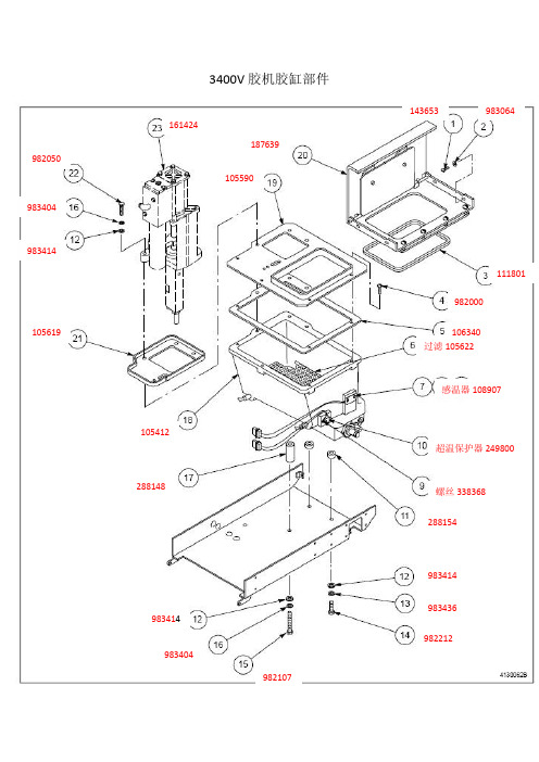
3400V胶机胶缸部件143653983064111801982000106340过滤105622感温器108907超温保护器249800螺丝3383682881549834149834369822129834042881481054121055901876391056199834149834149834049820501614243400V胶机壳体1056182883071824932344341436522254562254551055932254542881602344332882221056142309082308979830053400V 分歧座120324983414288023982096整个滤网105432 2745699412209402813100V胶机胶缸部件143653983064111800982000106339过滤105621感温器108907超温保护器249800螺丝3383682881549834149834369822129834042881481054111055891876261056199834149834149834049820501614243100V胶机壳体1056171448691824932344351436522254562254551055932254542881602344332882221056142309082308979830053100V 分歧座120324983414288023982096整个滤网105432 2745699412209402813000V通用过滤系统(105432)2745782745789411722745139817473000Vista TC 通用电气控制系统234423U 型弹簧锁母操作面板232682开关225451225450297706 含第4、5接头185092控制板248043螺丝9829712325403000Vista TC 活塞泵(161424)1.164601泵维修组件(包含图中1-11项及高温润滑油211228)2.166880 磁叉3.164606 泵换向执行机构4.120306 泵出口密封圈(包含白色和棕色密封圈)166880 164606ProBlue 胶机胶缸分歧座备件明细(P4、P7和P10)活塞泵活塞泵10283031064649 240VAC 1064650 400VAC 1017009 1017060 超温保护器1028321 连接管1017186 密封圈 94116111感温器1028320 感温器1028320P4&P7 1064651 P10 1064653P4 1025885 P7 1025885 P10 10178921017189泄压阀 1028308过滤网 1028305 P4 1051033 P7 1051034 P10 10510351028304 活塞泵维修组件(含高温润滑油) 1028307 ProBlue 胶机活塞泵控制机构(含电磁阀) 磁叉、执行机构的编号和3000系列胶机相同CPU板1028325操作面板P4&P7 1028326P10 1028327挡板1017223诺信喉管1. 按照使用性分防水型喉管、标准喉管和高弹性喉管2. 按喉管内径有9/16”和5/8” 两种3. 按照喉管本身使用的感温器分为RTD 、Feco 和PT100的喉管型号:5/16” , RTD 喉管用于自动喷枪喉管针脚定义(连接胶机一端)1 和 2: 胶枪加热器 3 和 5: 胶枪感温器 4 和 6 : 胶管加热器 5 和 8: 胶管感温器喉管的不正确安装方式:诺信喉管及胶枪胶机连接接头为了保证接头及胶枪、胶管和胶机的螺纹不被损坏,拆装时个部件必须在加热状态,连接胶机和胶枪一端时,先用手慢慢将接头拧入胶机分歧座或胶枪座的螺纹,直到密封圈进入到分歧座或胶枪上的槽内,然后调整好角度并用扳手将锁紧锁母锁死,连接喉管时同样用手拿住喉管一端的锁母,慢慢于接头连接,待全部扣戴正,且用手劲拧不动时,用两把扳手锁紧。
固态继电器手册
DownloadManual
K-160You’ll need these items to complete this kitSpecificationsLength: 78.5”Diameter 4.0”Weight: 76ozRecovery: 48” Nylon ChuteMotor Mount: 54mmFins: 6 - 1/4” PlywoodCG: 57” from nose tip(1) Nose Cone(1) Pre-slotted main body tube (31”)(1) Payload section body tube (31”)(2) Centering rings(1) Coupler(1) Bulkhead(1) Motor tube(6) laser-cut fins(2) Eyebolt, nut and washer(1) Nylon shock cord(2) Rail buttons, (2) screws, (1) weld nut(1) 12x12 Chute Protector (optional)(1) 48” Nylon chute (optional)Parts ListFRENZY5 Minute Epoxy120/220 SandpaperFiller and PaintPencilZap or CASuper GlueLead Shotfor BalanceMotor Retainer®898666001604Step 1 - Sand the glassine coating off of the motor tube.Epoxy will not stick very well to the glassine and roughing the tube will help the epoxy stick.Step 2 - Test fit the centering rings over the motor mount tube and sand if necessary. The ring should slide snug over the motor tube without deforming it. Also test fit the centering rings in the body tube and sand if necessary.Step 3 - One of the rings will have a hole for an eyebolt to attach the shock cord - this will be the forward ring. Spread some epoxy on the outside of one end of the motor tube and -Step 4 - After the forward ring is dry, spread some epoxy on the other side of the motor tube and slide the aft ring until there is 1/2” exposed on the aft end of the motor tube. VERY IMPORTANT: make sure there is not any epoxy on the mo-Step 7 - Wrap the shock chord into a small bundle and stuff it inside the motor tube for this next step. Test fit the motor tube assembly into the aft end (end closest to the slots) of the body tube to ensure a snug fit. Sand the centering rings if neces -sary.Step 8 - When you are satisfied with the fit, spread someepoxy on the inside of the body tube about 5” from the aft end and slide the forward centering ring of the motor assembly into the body tube. Make sure you have the motor as-sembly facing the right way - the centering ring with the eyebolt should slide in first!Keep going by spreading some more epoxy on the inside of the body tube near the aft edge before sliding the aft centering ring into the body tube. Continue sliding the assembly inside the body tube until the aft centering ring is all the way in body tube with the aft end of the motor tube lining up with the aft end of the body tube. It’s a good idea to test fit a fin in each slot here before the epoxy sets. Hold the body tube with the motor tube assembly down until the epoxy sets. Make sure the weight of the motor assembly doesn’t cause it to slide out of alignment.sure the eyebolt is aligned so that it will not interfere with the body tube when the motor assembly is inserted into the body Step 9 - Using a door jam or small section of angle stock, pen -Step 20 - Apply some epoxy to the inside of the coupler and push the bulkhead in so there is about a 1/8” to ¼” of cou -pler exposed. After the epoxy has set, apply a fillet of epoxy Step 10 - Test fit each of the fins into the pre cut fin slots. The fin should seat firmly against the motor tube - sand each fin if necessary.When you are satisfied with the fit, apply some epoxy to the end of the fin tang that will contact the motor tube as well as any fin root that will contact the body tube. Also, spread a thin layer of epoxy on each side of the fin tang. Slide the fin into place and check the alignment. Continue rechecking the fin alignment until you are sure the epoxy has set. Clean any excess epoxy from around the fin joint. Repeat for the Step 21 - Next mark the coupler 3” from the forward edge. Apply some epoxy to the inside of the forward body tube sec -tion and slide the coupler up to the mark. There should be 5” of coupler exposed. Make sure the coupler is straight and Step 16 - Insert the weld nut from the inside of the body tube through the previously drilled hole. You can hold the nut in place with a little CA if you like (be careful not to get any of the CA glue inside the threads. Place the rail button over the weld nut and secure with the short 6-32 screw. It is a good idea to Step 12 - It is also a good idea to CA the sharp tips of the fins to keep them from splintering on hard landings.Step 13 - Drill a 5/64” hole on the rail button line for the aft rail buttons ensuring the hole goes into the aft centering ring.Step 14 - Apply a small amount of epoxy in the hole and at -tach the rail button using the supplied #6 wood screw. Make sure the screw is loose enough for the rail button to spin freely - this ensures the button is not compressed to the point it will hang on the rail guide.Step 15 - Drill a 3/16” hole on the rail button line for the forward rail button. The forward hole should be 6” from the forward end of the main body tube. IMPORTANT: Make sure there is at least 6” from the forward end of the body tube or the rail button will interfere with the coupler.Flying Your ModelIMPORTANT: always use positive motor reten-tion to secure the motor. Failure to use motor retention will cause the motor to be ejected in-stead of the parachute making for a dangerous ballistic reentry.IMPORTANT: always remember to check your balance point and ensure your CG is forward of the specified CG point.IMPORTANT: Always follow the NAR safety code and remember that rockets are not toys and can be dangerous if not prepared and used properly. If you are a beginner, it is a good idea to fly with a club or other group of experienced rocketeers until you have gained some experi-ence.IMPORTANT: In no event shall Madcow Rocket-ry be liable for any direct, indirect, punitive, in -cidental, special consequential damages what -soever arising out of or connected with the use or misuse of it’s products. The buyer assumes all risk and liability resulting from ANY use of any and all products sold by Madcow Rocketry. Your purchase and use of any Madcow Rock-etry product constitutes your agreement to and acceptance of these terms. If you do not agree to these terms and conditions, you must return the unused product in resalable condition for a refund or credit.IMPORTANT: Please contact us via phone or email if you have any questions about con -structing or flying your model.24338 El Toro Rd #E-134Laguna Woods, CA 92637949.547.8847 **************************©2011 MadCow Rocketry™Balancing Your ModelStep 22 - Pack the chute and assemble the rocket. When packing your chute, wrap the chute protector around the chute with the opening in the chute protector facing forward. Always make sure your chute is well protected as the hot ejection mo -tor gasses will melt the nylon chute.Step 23 - Insert the largest motor that you intend to fly (orsimulate the weight with an appropriate substitute) and ensure that the CG (where the rocket balances front to back) is at or in front of the point defined in the specifications on the first page. The CG should be measured from the tip of the nosecone.Step 24 - If the CG is behind the specified point, add weight inside the nose cone by pouring lead shot into the nose cone and adding some epoxy. Hold the nose cone with the tip down so the weight will be as far forward as possible. IMPORTANT: Screw in several screws through the plastic nose cone into the lead to hold it in place. Grind or cut off the screw head before filling and applying the nose cone finish. The epoxy will not stick to the inside of the nose cone and if you do not anchor with screws, the liftoff force will cause the weight to become dislodged causing an unstable model. When you are satisfied with the balance of your model, attach the nose cone to the payloadsection.IMPORTANT: Proper CG is critical to the stability of this model. This model will require some ballast in the nose - the amount will depend on how you build and the size motor you use to fly. Do not fly without balancing this model properly as a dangerous un-stable flight will result.Step 29 - Your model is now ready to paint.At this point your model is ready to fly.Now go have some fun!Step 27 - Drill a small 1/8” hold in the chute compartment to allow venting. Make sure you do this without the chute in thechute compartment.Step 28 - At this point install your positive motor retention device. The kit does not include a motor retention device andthis will need to be purchased separately.Final AssemblyStep 25 - Using the same knot you used in step 6, attach theother end of the shock cord to the payload section eyebolt.Step 26 - Attach the parachute to the shock cord near the nose cone. Also attach the chute protector to the shock cordnear the nose cone.®。
E-3000控制器使用说明书
E3000控制器使用说明书目录1. 安全上的注意事项、标记....................................P. 22. 特征......................................................P. 43. 规格及外观图..............................................P. 44. 系统结构..................................................P. 65. 扭力输出特性图............................................P. 76. 各部分的名称..............................................P. 97. 保险丝的更换方法..........................................P.118. 托架及橡胶垫脚的安装方法..................................P.119. 电源线的连接方法..........................................P.1310. 马达线的连接方法..........................................P.1311. 风管的连接方法............................................P.1412. 操作方法..................................................P.1513. 外部输入/输出连接器.......................................P.1814. 保护功能..................................................P.2715. 参数的设定方法............................................P.2916. 试运转方法................................................P.3717. 故障的原因及对策..........................................P.38非常感谢您此次购买E3000控制器。
电动伺服器 滑动类型系列LEKFS E产品说明书
Instruction ManualElectric Actuator / Slider type Series LEKFS**EMotor: Step motor (servo 24 VDC) with Battery-less absolute encoderThe intended use of this Electrical Actuator is to convert an electrical input signal into mechanical motion.1 Safety InstructionsThese safety instructions are intended to prevent hazardous situations and/or equipment damage. These instructions indicate the level of potential hazard with the labels of “Caution,” “Warning” or “Danger.” They are all important notes for safety and must be followed in addition to International Standards (ISO/IEC) *1), and other safety regulations. *1)ISO 4414: Pneumatic fluid power - General rules relating to systems. ISO 4413: Hydraulic fluid power - General rules relating to systems.IEC 60204-1: Safety of machinery - Electrical equipment of machines. (Part 1: General requirements)ISO 10218-1: Manipulating industrial robots -Safety. etc.∙ Refer to the product catalogue, Operation Manual and Handling Precautions for SMC Products for additional information. ∙ Keep this manual in a safe place for future reference.CautionCaution indicates a hazard with a low level of risk which, ifnot avoided, could result in minor or moderate injury.WarningWarning indicates a hazard with a medium level of riskwhich, if not avoided, could result in death or serious injury.DangerDanger indicates a hazard with a high level of risk which, ifnot avoided, will result in death or serious injury.Warning∙ Always ensure compliance with relevant safety laws and standards. All work must be carried out in a safe manner by a qualified person in compliance with applicable national regulations.2 SpecificationsLEKFS25 seriesModelLEKFS25 A c t u a t o r s p e c i f i c a t i o nStroke [mm] 100 to 500Max. work load [kg]Horizontal 12 25 30 Vertical0.57.515 Speed [mm/s] Note 1)In-Line to 500 stroke 20 to 1100 12 to 750 6 to 400 Parallel to 500 stroke20 to 90012 to 600 6 to 300Max. acceleration / deceleration [mm/s 2]3,000Positioning repeatability [mm] ±0.01 (lead H: ±0.02)Lost motion [mm] Note 2) 0.05 or less Screw Lead [mm]2012 6Impact/Vibration resistance [m/s 2] Note 3) 50 / 20 Actuation method Ball screw Guide typeLinear guide Operating temperature [℃] 5 to 40Operating humidity [%RH] 90 or less (no condensation)E l e c t r i c a lMotor size [mm] □42Motor typeBattery-less absolute (Step motor 24 VDC) Encoder(angular displacement sensor) Battery-less absolute (4096 pulses / rotation)Rated Voltage [V]24 VDC ±10%Power consumption [W] Note 4) 38Standby power consumption [W] Note 5)16 Max. instantaneous power consumption [W] Note 6) 57L o c kLock Type Note 7)Non magnetizing lock Holding force [N] 4778 157Power consumption [W] Note 8)5 Rated voltage [V]24 VDC ±10%LEKFS32 seriesModelLEKFS32 A c t u a t o r s p e c i f i c a t i o nStroke [mm] 100 to 500Max. work load [kg]Horizontal 20 45 50 Vertical41020 Speed [mm/s] Note 1)In-Line to 500 stroke 24 to 1200 16 to 800 8 to 400 Parallel to 500 stroke24 to 800 16 to 6508 to 325Max. acceleration / deceleration [mm/s 2]3,000Positioning repeatability [mm] ±0.01 (lead H: ±0.02)Lost motion [mm] Note 2)0.05 or lessScrew Lead [mm]2416 8Impact/Vibration resistance [m/s 2] Note 3) 50 / 20 Actuation method Ball screw Guide typeLinear guide Operating temperature [℃] 5 to 40Operating humidity [%RH] 90 or less (no condensation)E l e c t r i c a lMotor size [mm] □56.4Motor typeBattery-less absolute (Step motor 24 VDC) Encoder(angular displacement sensor) Battery-less absolute (4096 pulses / rotation)Rated Voltage [V]24 VDC ±10%Power consumption [W] Note 4) 50Standby power consumption [W] Note 5)44 Max. instantaneous power consumption [W] Note 6) 123L o c kLock Type Note 7)Non magnetizing lock Holding force [N] 72108 216Power consumption [W] Note 8)5 Rated voltage [V]24 VDC ±10%2 Specifications (continued)L o c kLock Type Note 7)Non magnetizing lock Holding force [N] 75113 225 Power consumption [W] Note 8)5 Rated voltage [V]24 VDC ±10%Note 1) Speed varies according to the work load. Check the “Speed–Work LoadGraph" as a Guide in the catalogue on the SMC website (URL: https:// ).Furthermore, if the cable length exceeds 5 m, then the speed and work load may decrease by up to 10% for each additional 5 m.Note 2) A reference value for correcting an error in reciprocal operation.Note 3) Impact resistance: No malfunction occurred when the actuator was testedwith a drop tester in both an axial and a perpendicular direction to the lead screw. The test was performed with the actuator in the initialized state. Vibration resistance: No malfunction occurred in a test ranging between 45 to 2000 Hz. The test was performed in both an axial and a perpendicular direction to the lead screw. The test was performed with the actuator in the initialized state.Note 4) The power consumption including the controller is for when the actuator isoperating.Note 5) Standby power consumption when operating (including the controller) iswhen the actuator is stopped in the set position during a positioning operation.Note 6) Maximum instantaneous power consumption (including the controller) iswhen the actuator is operating. This value can be used for the power supply selection.Note 7) For models with lock only.Note 8) For an actuator with lock, add the power consumption for the lock.2.1 Product weightSeriesLEKFS25 Stroke [mm]100 200 300 400 500 Product weight [kg] 1.82.12.4 2.62.9Lock weight [kg]0.3SeriesLEKFS32Stroke [mm]100 200 300 400 500 Product weight [kg] 3.33.74.2 4.65.0Lock weight [kg] 0.52 Specifications (continued)SeriesLEKFS40 Stroke [mm]200 300 400 500 600 Product weight [kg] 5.76.36.97.58.1Lock weight [kg]0.5WarningSpecial products (-X#, -D#) might have specifications different from those shown in this section. Contact SMC for specific drawings.3 Installation3.1 InstallationWarning∙ Do not install the product unless the safety instructions have been read and understood.∙ Do not use the product in excess of its allowable specification.∙ When installing, inspecting or performing maintenance on the product, be sure to turn off the power supplies. Then, lock it so it cannot be tampered with while work is happening.∙ Keep the flatness of the mounting surface to within 0.1 mm maximum. Insufficient flatness of a work piece or actuator mounting surface can cause play in the guide and increased sliding resistance. In the case of overhang mounting (including cantilever), use a support plate or support guide to avoid deflection of the actuator body.∙ When mounting the actuator, use all mounting holes.If all mounting holes are not used, this will not maintain the specified performance. e.g. the amount of displacement of the table will increase. ∙ When mounting the actuator leave a gap of 40 mm or more to allow for bending of the actuator cable.∙ When mounting the actuator or workpiece, use screws with adequate length and tighten them with adequate torque.Tightening the screws with a torque higher than recommended may cause malfunction, whilst tightening with a torque lower than recommended can cause displacement of the mounting position, or dropping of the work piece.Model Screw sizeMax. tightening torque [N.m]∅ A [mm]L [mm] LEKFS25 M4 1.5 4.5 24 LEKFS32 M5 3.0 5.5 30 LEKFS40M65.26.631ORIGINAL INSTRUCTIONSLEKFS40 seriesModelLEKFS40 A c t u a t o r s p e c i f i c a t i o nStroke [mm] 200 to 600Max. work load [kg] Horizontal 25 55 65 Vertical 2223Speed [mm/s]Note 1) In-Line to 500 stroke30 to 1200 20 to 850 10 to 300 501 to 600 stroke30 to 1200 20 to 850 10 to 300 Parallel to 500 stroke30 to 750 20 to 550 10 to 300 501 to 600 stroke 30 to 750 20 to 550 10 to 300Max. acceleration / deceleration [mm/s 2] 3,000Positioning repeatability [mm] ±0.01 (lead H: ±0.02)Lost motion [mm] Note 2) 0.05 or lessScrew Lead [mm] 3020 10Impact/Vibration resistance [m/s 2] Note 3) 50 / 20 Actuation method Ball screw Guide type Linear guide Operating temperature [℃] 5 to 40Operating humidity [%RH] 90 or less (no condensation)E l e c t r i c a lMotor size [mm] □56.4Motor type Battery-less absolute (Step motor 24 VDC) Encoder (angular displacement sensor) Battery-less absolute (4096 pulses / rotation)Rated Voltage [V] 24 VDC ±10%Power consumption [W] Note 4) 100 Standby power consumption [W] Note 5) 43 Max. instantaneous power consumption [W] Note 6) 141L o c kLock Type Note 7)Non magnetizing lock Holding force [N] 75113 225Power consumption [W] Note 8)5Rated voltage [V] 24 VDC ±10% Actuator Mounting3 Installation (continued)Work piece Mounting∙In order to prevent the work piece fixing screws from damaging the table, use screws at least 0.5 mm shorter than the maximum thread depth. Longer screws can hit the body and cause operation failure.Model Screw size Max. tighteningtorque [N.m]L Max. threaddepth [mm]LEKFS25M5 x 0.8 3.0 8LEKFS32 M6 x 1.0 5.2 9LEKFS40M8 x 1.25 12.5 133.2 EnvironmentWarning∙Do not use in an environment where corrosive gases, chemicals, salt water or steam are present.∙Do not use in an explosive atmosphere.∙Do not expose to direct sunlight. Use a suitable protective cover.∙Do not install in a location subject to vibration or impact in excess of the product’s specificatio ns.∙Do not mount in a location exposed to radiant heat that would result in temperatures in excess of the product’s specifications.∙Prevent foreign particles from entering the product.3.3 MountingWarning∙Observe the required tightening torque for screws.Unless stated otherwise, tighten the screws to the recommended torque for mounting the product.∙Do not make any alterations to the product.Alterations made to this product may lead to a loss of durability and damage to the product, which can lead to injury and damage to other equipment and machinery.Do not scratch or dent the sliding parts of the table or mounting face etc., by striking or holding them with other objects. The components are manufactured to precise tolerances, so that even a slight deformation may cause faulty operation or seizure.∙Do not use the product until it has been verified that the equipment can be operated correctly.After mounting or repair, connect the power supply to the product and perform appropriate functional inspections to check it is mounted correctly.∙Do not use the product until it has been verified that the equipment can be operated correctly.After mounting or repair, connect the power supply to the product and perform appropriate functional inspections to check it is mounted correctly.3.4 LubricationCaution∙SMC products have been lubricated for life at manufacture, and do not require lubrication in service.∙If a lubricant is used in the system, refer to the catalogue for details. ∙The recommended grease is lithium grade No.2Apply for Grease Pack order No.Ball screw and Guide GR-S-010(10g)GR-S-020(20g)4 Wiring4.1 WiringWarning∙Adjustment, mounting or wiring changes should not be carried outbefore disconnecting the power supply to the product.Electric shock, malfunction and damage can result.∙Do not disassemble the cables.∙Use only specified cables.Use only specified cables otherwise there may be risk of fire anddamage.∙Do not connect or disconnect the wires, cables and connectors whenthe power is turned on.Caution∙Wire the connector correctly and securely.Check the connector for polarity and do not apply any voltage to theterminals other than those specified in the Operation Manual.∙Take appropriate measures against noise.Noise in a signal line may cause malfunction. As a countermeasureseparate the high voltage and low voltage cables, and shorten thewiring lengths, etc.∙Do not route input/output wires and cables together with power or highvoltage cables.The product can malfunction due to noise interference and surgevoltage from power and high voltage cables close to the signal line.Route the wires of the product separately from power or high voltagecables.∙Take care that actuator movement does not catch cables.∙Operate with all wires and cables secured.∙Avoid bending cables at sharp angles where they enter the product.Avoid twisting, folding, rotating or applying an external force to thecable. Risk of electric shock, wire breakage, contact failure and loss ofcontrol of the product can result.∙Select “Robotic cables”in applications where cables are movingrepeatedly (encoder/ motor/ lock).∙Confirm correct insulation.Poor insulation of wires, cables, connectors, terminals etc. can causeinterference with other circuits. Also there is the possibility thatexcessive voltage or current may be applied to the product causingdamage.∙R efer to the auto switch references in “Best Pneumatics“ when an autoswitch is to be used4.2 Wiring of Actuator to Controller4.3 Actuator Ground connection∙The Actuator must be connected to ground to shield the actuator fromelectrical noise. The screw and cable with crimping terminal andtoothed washer should be prepared separately by the user.∙The ground wire cross sectional area should be 2 mm2 minimum.∙Avoid shared grounding points with other devices.5 How to OrderRefer to the catalogue on the SMC website(URL: https://) for the How to Order information.6 Outline Dimensions (mm)Refer to the drawings / operation manual on the SMC website(URL: https://) for outline dimensions.7 Maintenance7.1 General MaintenanceCaution∙Not following proper maintenance procedures could cause the productto malfunction and lead to equipment damage.∙If handled improperly electricity and compressed air can be dangerous.∙Maintenance of electromechanical and pneumatic systems should beperformed only by qualified personnel.∙Before performing maintenance, turn off the power supply and be sureto cut off the supply pressure. Confirm that the power has beendischarged and the air is released to atmosphere.∙After installation and maintenance, apply operating pressure andpower to the equipment and perform appropriate functional andleakage tests to make sure the equipment is installed correctly.∙If any electrical or pneumatic connections are disturbed duringmaintenance, ensure they are reconnected correctly and safety checksare carried out as required to ensure continued compliance withapplicable national regulations.∙Do not make any modification to the product.∙Do not disassemble the product, unless required by installation ormaintenance instructions.∙Incorrect handling can cause an injury, damage or malfunction of theequipment and machinery, so ensure that the procedure for the task isfollowed.∙Always allow sufficient space around the product to complete anymaintenance and inspection.7.2 Periodical Maintenance∙Maintenance should be performed according to the table below:FrequencyAppearanceCheckInternalcheckBeltCheckBefore daily operation ✓Every 6 months* ✓✓✓Every 1,000 km* ✓✓✓Every 5 million cycles* ✓✓✓*whichever of these occurs first.∙Following any maintenance, always perform a system check. Do notuse the product if any error occurs, as safety cannot be assured ifcaused by any un-intentional malfunction.7.3 Appearance Check∙The following items should be visually monitored to ensure that theactuator remains in good condition and there are no concerns flagged;・Loose Screws,・Abnormal level of dust or dirt,・Visual flaws / faults,・Cable connections,・Abnormal noises or vibrations.7.4 Belt Check∙If one of the 6 conditions below are seen, do not continue operatingthe actuator, contact SMC immediately.・Tooth shaped canvas is worn out.Canvas fibre becomes “fuzzy”, rubber is removed, and the fibre gainsa white colour. The lines of fibre become very unclear.・Peeling off or wearing of the side of the belt.The corner of the belt becomes round and frayed, with threadsbeginning to stick out.・Belt is partially cut.Belt is partially cut. Foreign matter could be caught in the teeth andcause flaws.・Vertical line of belt teeth.Flaw which is made when the belt runs on the flange.・Rubber back of the belt is softened and sticky.・Crack on the back of the belt.8 Limitations of Use8.1 Limited warranty and Disclaimer/Compliance Requirements∙Refer to Handling Precautions for SMC Products.9 Product disposalThis product should not be disposed of as municipal waste. Check yourlocal regulations and guidelines to dispose of this product correctly, inorder to reduce the impact on human health and the environment.10 ContactsRefer to or www.smc.eu for your local distributor /importer.URL : http// (Global) http// www.smc.eu (Europe)SMC Corporation, 4-14-1, Sotokanda, Chiyoda-ku, Tokyo 101-0021, JapanSpecifications are subject to change without prior notice from the manufacturer.© 2021 SMC Corporation All Rights Reserved.Template DKP50047-F-085MElectric Actuator / Slider typeJXC#1 ControllerActuator cableLE-CP-*(no lock or sensor)LE-CP-*-B(with lock and sensor)。