AC驱动相关问题
“问题驱动教学法”的实践与反思

“问题驱动教学法”的实践与反思问题驱动教学法(Problem-Based Learning, PBL)是一种以问题为核心、学生自主学习、团队合作的教学方法。
本文将结合实际教学经验,从实践和反思的角度探讨问题驱动教学法的优点和局限性,并提出相应的改进建议。
一、问题驱动教学法的实践在问题驱动教学法中,教师通常会设计一个开放性的问题,让学生在小组中讨论并解决。
学生们通过阅读、讨论、研究和实践,自主获取知识,培养问题解决能力和团队合作意识。
在我自己的教学实践中,我深刻体会到了问题驱动教学法的许多优点。
问题驱动教学法能够激发学生的学习兴趣和动力。
在传统的教学模式下,学生可能只是被动地接受知识,而问题驱动教学法则更加注重学生的主动参与和探究。
学生们在尝试解决问题的过程中,会产生强烈的求知欲望,自觉地去寻找答案,从而激发出他们内在的学习动力。
问题驱动教学法能够培养学生的批判性思维和解决问题的能力。
通过与同学的讨论和交流,学生们会接触到不同的观点和想法,从而培养出批判性思维。
在解决实际问题的过程中,学生们还会逐渐培养出解决问题的能力,这对于他们未来的职业发展具有非常重要的意义。
问题驱动教学法还能够促进学生的自主学习和团队协作能力。
在问题驱动的学习环境下,学生们需要自主地搜集、整理和分析相关的信息,同时还需要和同学们进行讨论和合作。
这种学习模式能够培养学生的自主学习和团队协作的能力,从而更好地适应未来社会的需求。
从教学实践来看,问题驱动教学法能够在很大程度上激发学生的学习兴趣和动力,同时培养学生的批判性思维和解决问题的能力,促进学生的自主学习和团队协作能力。
问题驱动教学法也存在着一些不足之处,需要我们在实践中进行反思和改进。
在实际教学中,我也发现了问题驱动教学法的一些不足之处。
问题设置可能存在难易不均。
有时候,教师在设计问题的时候可能会偏向于过于简单或者过于复杂,导致学生们无法有效地解决问题。
学生的自主学习意识和团队协作能力可能存在欠缺,一些学生可能会依赖他人,缺乏主动探究的精神。
AC-PDP驱动电路关键技术分析与比较
t.Z ei g Wal U iesy D P K y L b r oy t曲 oZ ein 1 1o hn ; 1 hj n ni nvri S e aoa r,Nn hj g 3 5 o,C ia a t t a
【 y w rs D ;d v gcru ;A S LS E E Ke o d 】P P r i i i D ;A I;T R S i n ct
1 引 言
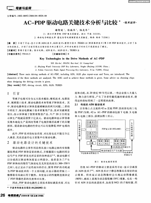
等 离 子 电视 可分 为 五 大 技 术 模 块 : 机 技 术 、 源 技 整 电 术 、 频 接 口技 术 、 动 电路 技 术 和 等 离 子 屏 体 技 术 。其 视 驱 中 , 动 电路 和 显 示 屏 体 是 最 难 解 决 的两 大 问题 。 者 的 驱 二 不 同在 于 , 动 电 路 属 于 技 术 密 集 型 产 品 , 术 突 破 难 度 驱 技 很 大 ; 示 屏 体 属 于投 资 密 集 型 产 品 , 产 2 显 年 0万 台 的 显 示 屏 生 产 线 就 需 投 资 2亿 美 元 。驱 动 电路 和 显示 屏 很 难 实现 本 地 化 生 产 是 国 内等 离 子 电视 价格 居 高 难 下 的 关 键
Y
原 因。 提高驱 动电路的性 价 比可 以有效 降低 P P电视 的 D
成本 。 圆 圆
光 耦
P P D 显示 屏 ( 5 x 8 8 2 4 0)
X
电 极
驱
此 外 ,D P P技 术 指 标 如 亮 度 、 比度 也 还 不 能 完 全 让 对 人 满意 , 改 进 途 径 也 主 要 集 中在 驱 动 电路 。 其
AC基础知识重要术语
是
是
否
是
力波数量铺货率: 75% 力波加权铺货率: 80%
铺货主要用于衡量: - 产品目前的市场渗透程度如何? - 我们的铺货质量如何?
- 我们所有的单品是否得到了平等的铺货支持?
- 我们是否错失了铺货机会?
- 我们的销售队伍是否实现了铺货目标?
零售研究服务
数据综合整合
• 数据的使用必须综合考虑以下因素: - 历史趋势 - 特定目标 - 与市场整体/竞争对手的相对比例 - 自身的运作模式 - 媒体/促销投入 - 其它消费者行为/习惯的资料
数量铺货率(Numeric Distribution):
售卖该种商品的商店数量的百分比,不计商店的类型、销 售额的重要性
加权铺货率(Weighted Distribution):
售卖该种商品的商店的总体品类销售额占所有商店总体品类销售额的 百分比
整个品类销售额
$20
$力波产品
• 尼尔森数据帮你解决: – 零售市场的趋势和变化 – 各品类的发展趋势 – 产品发展以及价格策略 – 自己以及竞争对手的市场份额
市场管理
• 市场部门关心的问题: – 营销组合: • 产品(分类、包装、容量) • 价格(定价策略、产品价格) • 促销 • 陈列 – 监控销售计划的实施 – 建立信息平台,并监督实施
等到它有货为止
Base: All respondents who buy regularly
• 我们有的时候会遇到这样问题:
– 为什么一个产品的加权铺货在快速的上升,但 销售却增长缓慢或维持原有的水平?
常用指标—— SPPD/SIH 单点卖力
去除铺货高低带来的份额升降,我在商店中的卖力怎样?
单点销售Sales Per Point of Distribution:
无线局域网按钮灰色

无线局域网按钮灰色无线局域网按钮灰色通常是指在电脑或移动设备上,无线局域网(Wi-Fi)的开关按钮显示为灰色,无法点击或激活。
这种情况可能由多种原因导致,以下是一些可能的原因和相应的解决方法:1. 驱动程序问题:无线网卡的驱动程序可能出现问题或过时。
解决此问题的方法是更新或重新安装无线网卡的驱动程序。
可以通过设备管理器查找无线网卡,然后右键点击选择“更新驱动程序”或“卸载设备”。
在卸载后,重新启动设备,系统将尝试自动重新安装驱动程序。
2. 硬件开关:许多笔记本电脑都有一个物理开关或键盘快捷键来控制无线网卡的开启和关闭。
请检查您的设备是否有这样的开关,并确保它处于开启状态。
3. BIOS设置:有时无线网卡可能在BIOS中被禁用。
重启电脑进入BIOS设置,查找与无线网卡相关的选项,并确保它被启用。
4. 系统服务:某些系统服务可能控制着无线网卡的功能。
打开“服务”应用程序,检查与无线网络相关的服务(如WLAN AutoConfig)是否正在运行。
如果未运行,尝试启动这些服务。
5. 系统故障:操作系统可能存在故障,导致无线局域网按钮显示为灰色。
尝试重启电脑,或者在安全模式下启动,看是否可以解决问题。
6. 硬件故障:如果以上方法都无法解决问题,可能是无线网卡硬件出现了故障。
这种情况下,可能需要联系设备制造商或专业技术人员进行进一步的检查和维修。
7. 操作系统限制:在某些情况下,操作系统可能因为安全或策略设置限制了无线网络的使用。
检查系统设置,确保没有启用任何可能限制无线网络访问的设置。
8. 软件冲突:某些第三方软件可能与无线网卡的正常工作发生冲突。
尝试关闭或卸载最近安装的软件,看是否解决了问题。
9. 网络设置:检查网络设置,确保无线网络配置正确无误。
有时错误的网络设置也可能导致无线局域网按钮显示为灰色。
10. 系统更新:操作系统的更新可能会引入新的设置或修复已知的问题。
确保您的操作系统是最新的,并检查更新日志,看是否有与无线网络相关的更新。
LS电子标准AC驱动S100说明书

S1000.4~2.2kW(0.5~3HP) 1-Phase 200~240Volts0.4~15kW(0.5~20HP) 3-Phase 200~240Volts0.4~75kW(0.5~100HP) 3-Phase 380~480VoltsIP66 NEMA4X 0.4~2.2kW(0.5~3HP) 1-phase 200V~240VoltsIP66 NEMA4X 0.4~15kW(0.5~20HP) 3-Phase 200~240VoltsIP66 NEMA4X 0.4~22kW(0.5~30HP) 3-Phase 380~480Volts2C o n t e n t s0410121417212832S100 Features IP66/NEMA 4X Model and Type SpecificationsWiring / Terminal Configuration Keypad Functions Peripheral Devices DimensionsPowerful sensorless control, and a diverse range of user friendly functions delivers added value to our customers.Meet the new standard drive S100 by LS for the global market.Strong Power with a Compact Size !S10 0High-performanceStandard Drive3High-performance Standard Drive• Built-in safe torque off (STO) • Redundant input circuitSafetyFunctions • Sensorless control functions• Starting torque (200%/0.5Hz)Strong Performance• Side-by-side installation • Decreased dimensions Space EfficientDesign • Various field networksSuitable for Users• Built-in EMC filter • International standardsStandard ComplianceScan the QR code on your drive front and check the key use information4Specialized FeaturesS100 Improves User Convenience with Smart Copier .Drive Control PartDrive Input/Output Part (Flash Memory)Auto-synchronization When Power-onSmart Copier Receives From Drive Input/Output PartSmart Copier Sends to Drive Input/Output PartRead Parameter Memory Write Parameter MemorySmart CopierSmart Copier Flow ChartThe drive does not need to be powered when using the smart copier.Functions Without Power InputI/O input and output can be shared among master and slave drive (RS485 wiring required)P2P Function EmbeddedThe run LED flickers during normal operation. The error LED flickers when events such as communication errors occur.LED Lamp FeedbacksParameters can be copied/loaded from the drive to the smart copier and vise versa,simply with the keypad.Read / Write Function of ParametersMultiple drives can be controlled and monitored with single keypad. (RS485 wiring required)Multi Keypad FunctionParameters saved in the smart copier can be down-loaded to both the drive I/O and the control part.Simple InstallationSimple PLC sequences can be operated with various function block combinations.User Sequence FunctionUser ConvenienceRJ45(Included if Smart Copiers are Purchased)Smart CopierGraphic LCD can be used for parameter copy from drive to drive.6Suitable for UsersS100 Offers a Variety of Customer Conveniencesto Compete in the Global Market.① Profibus-DP ④ CANopen ② Ethernet IP ⑤ EtherCAT ③ Modbus TCP⑥ PROFInet[Various Field Bus Options]Various Field Bus Options Easy to Install and Use.Conduit Kit Acquired UL open type & enclosed type1 certification※ UL open type is offered as default※ UL enclosed type1 needs conduit kit(option) installationThe heat sink can be mounted outside of the panel in case the space is limited.Flange Type• Relay output: 2ea (NO/NC selectable)• Digital input: 3ea (NPN/PNP selectable)• Analog I/O: 2ea/1ea eachExtension I/O Option CardPossible to connect to a variety of fieldbus networks Easy maintenance and mountingSimple Cooling Fan ReplacementReplaceable fan without complete disassemblyMasterSlave2Slave1※ LCD keypad (same as iS7 model) enables handy parameter set up.※ Multi language support will be available.Multi-Keypad FunctionSingle LCD keypad can be used to set up the parameters of a RS485 connected drives.Parameter Change with a Keypad.7High-performance Standard DriveDriveView9 Connection with RJ45 PortiS7 Normal CableRJ45 to USB Cable* RJ45 to USB Cable : Available as option8Space Efficient DesignS100 Increases Efficiency of the Control Panel.50mm50mm2mm2mm50mm 50mm50mm50mmiG5A (500mm) S100 (404mm) Minimized distance between drives enables panel size reduction for multiple drives installation.Side-by-side InstallationMain components have been optimally designedthrough thermal analysis and 3D design to reducethe dimension up to 60% compared to iG5A.Smaller SizeHDWSize Reduction60%400V 11kW Basis9High-performance Standard DriveStandard ComplianceS100 Has Built-in Safety Functions Suitable for Modern Safety Standards.※ Safety relay needs to be purchased separately.Main PowerSafety RelaySC 24VSA SBGate BlockMControl Circuit• Meets the electrical noise reduction regulation.• Related standards: 2nd Environment/Category C3(Class A) - CE standard is certified※ 1-phase 200V 0.4~2.2kW (C2) / 3-phase 400V 0.4~45kW (C3]Designed to be used for heavy and normal duty applications.• Overload capacity - H eavy duty operation: 150% of rated current, 60 seconds - Normal duty operation: 120% of rated current, 60 seconds※ Excludes IP66/NEMA 4XDual Rating OperationThe Safety input function meets EN ISO 13849-1 PLd and EN 61508 SIL2 (EN60204-1, stop category 0).This feature is standard and enables compliance with current safety standards.Built-in Safe Torque Off(STO)Built-in EMC FilterEffective in improving power factor and decreasing THD.※ 3-phase 400V 30~75kWBuilt-in DC ReactorRedundant Input CircuitStandstill or rotary auto-tuning options are available as standard to find motor constants with or without rotating the motor for optimized motor performance.Selectable Rotary / Standstill Auto-tuningGlobal standard complianceGlobal Compliance10High-performance Standard DriveS100 IP66/NEMA 4X SeriesProtected Against Foreign Substances Such as Fine Dust and High Pressure Water Spray.• Satisfies NEMA standard type 4X for indoor use.• Satisfies IEC 60529 standard IP66•1Ø 200V 0.4~2.2kW / 3Ø 200V 0.4~15kW / 3Ø 400V 0.4~22kW • PDS / Non-PDS (PDS; Power Disconnect Switch)The Drive for Harsh Ambient Conditions.IP66 / N EMA 4X※ (F): Built-in EMC or Non-EMC type selectable ※ 55~75kW satisfies EMC class 3* For the rated capacity, 200 and 400V class input capacities are based on 220 and 440V, respectively.* The rated output current is limited depending on the setup of carrier frequency (CN-04).* The output voltage becomes 20~40% lower during no-load operations to protect the drive from the impact of the motor closing and opening (0.4~4.0kW models only). * Dual rating is supported except IP66/NEMA 4X* For the rated capacity, 200 and 400V class input capacities are based on 220 and 440V, respectively.* The rated output current is limited depending on the setup of carrier frequency (CN-04).* The output voltage becomes 20~40% lower during no-load operations to protect the drive from the impact of the motor closing and opening (0.4~4.0kW models only). * Dual rating is supported except IP66/NEMA 4Xequest saLes peRson FoR ensoRLess FunctionDC InputShort Bar2) Use copper wires with 600V, 75°C specification.connected .DC ReactorBraking ResistorR(L1)S(L2)T(L3)P1(+)P2(+)BN(-)U V WR(L1)S(L2)T(L3)P2(+)P3(+)N(-)U V WDC InputBraking Unit1)2) Standard I/O is only provided for P5.3) In case of Standard I/O, Pulse input TI and multi-function terminal P5 share the same terminal. Set the ln.69 P5 define to 54(TI).4) In case of Standard I/O, Pulse output TO and multi-function output Q1 share the same terminal. Set the OU.33Q1 define to 38(TO).S+S-SG VR V1CM I2AO P5P6P7CM SA SB SC TO A1B1C1Q1EG24P1P2P3P4TIS+S-SG VR V1CM I2AOP4P5CM SA SB SC A1B1C1Q1EG24P1P2P30.4~22kW30~75kW0.4~22kWStandard I/OMultiple I/OStandard I/O※ LSLV-S100 can be supplied with either standard I/O or multiple I/O※ I/O board is supplied built in. IS7 LCD loader can be mounted on the front of the drive. ※ NC: Terminal not in use.DisplayFWD during acceleration/deceleration)operationSETLearning how to operate a S100(Smart device with android)2) Visible only when setting the function item of In.65~71 multi-function input terminal as no.26(2nd motor).1) Indicates only the target frequency when LCD keypad is installed. The first code of the operation group is a place to set a target frequency. It had been set as 0.00 when shipping fromthe factory, however, if a user changes the operating frequency, it indicates the changed operating frequency.2) Visible only when setting the function item of In.65~71 multi-function input terminal as no.26(2nd motor).Therefore, an over current trip (OCT) or over voltage trip (OVT) may occur when there is a low-resistance ground fault.1)If you do not want to enter the modified value, you can press the left, right, up or down keys (◀) (▶) (▲) (▼) except the enter key (ENT) in the ON condition to cancel the input.calculated at twice the standard.• The resistance/rated capacity/braking torque/%ED of DB Resistor are valid only for the DB unit of type A and the values of DB Resistor for type B and C refer to the manual of DB Unit..• Rating Watt of DBU has to be doubled when %ED is doubled.• It is not necessary to use option type dynamic braking unit for S100 below 22kW capacity because basically the dynamic braking unit is built in.• You must refer to dynamic braking unit manual for usage recommended dynamic braking unit in the table above due to changeable table.Terminal ArrangementGroup 1Group 3Group 2 :Group 4, 5braking unit.LSLV0022S100-1 / 0037S100-2 / 0037S100-4 / 0040S100-2 / 0040S100-4LSLV0004S100-1 / 0004S100-4 / 0008S100-4 (Built-in EMC)LSLV0008S100-1 / 0015S100-1 / 0015S100-4 / 0022S100-4 (Built-in EMC)LSLV0022S100-1 / 0037S100-4 / 0040S100-4 (Built-in EMC)LSLV0055S100-2 / 0075S100-2 / 0055S100-4 / 0075S100-4LSLV0110S100-2 / 0110S100-4 / 0150S100-4LSLV0150S100-2 / 0185S100-4 / 0220S100-4LSLV0300S100-4LSLV0370S100-4 / 0450S100-4LSLV0550S100-4 / 0750S100-4IP66(NEMA4X) 0.4~4.0kWIP66(NEMA4X) 5.5~7.5kWIP66(NEMA4X) 11~22kWCommunication Option Module (Installation Example)Conduit OptionConduit Option1) eMc LteRBuiLt-in c La※c onduit s ize:1/2inches(Ø:22.3MM),3/4inches(Ø:28.6 MM) 1 inches (Ø : 35 MM), 1+1/4 inches (Ø : 44.5 MM)1) eMc LteRBuiLt-in c Lass3 ※c onduit s ize:1/2inches(Ø:22.3MM),1+1/4inches(Ø:44.5MM) 1+1/2 inches (Ø : 50.8 MM), 2 inches (Ø : 63.5 MM)Flange OptionFlange OptionFlange Option。
AC Servo Motor 750W 与驱动器说明书

AC SERVO MOTOR 750W & DRIVERMODEL: MSMF082L1U2M + MCDLN35SGServo Motor Specification:Type Low inertia, Lead wire typeFamily Name MINAS A6Enclosure IP65About Enclosure Except rotating portion of output shaft and lead wire end. Environmental Conditions For more details, please refer to the instruction manual. Flange sq. dimension 80 mm sq.Flange sq. dimension (Unit: mm) 80Motor lead-out configuration Lead wireMotor encoder connector Lead wirePower supply capacity (kVA) 1.3Voltage specifications 200 VRated output 750 WRated current (A (rms)) 4.1Holding brake withoutMass (kg) 2.3w w w.e k t2.c o mOil seal withShaft Key-way, center tap Rated torque (N ⋅ m) 2.39 Continuous stall torque (N ⋅ m) 2.39 Momentary Max. peak torque (N ⋅ m) 7.16Max. current (A (o-p)) 17.4Regenerative brake frequency Without option: No limitWith option: No limit, Option (External regenerative resistor) Part No. : DV0P4283About regenerative brake frequency Please refer to the details of [Motor SpecificationDescription] , Note: 1, and 2.Rated rotational speed (r/min) 3000Rated rotational Max. speed (r/min) 6000Moment of inertia of rotor( x10-4 kg⋅m²)0.96Recommended moment of inertia ratio ofthe load and the rotor 20 times or lessAbout recommended moment of inertia ratio of the load and the rotor Please refer to the details of [Motor Specification Description] ,Note: 3.Rotary encoder: specifications 23-bit Absolute/Incremental systemNotice When using a rotary encoder as an incremental system (not using multi-turn data), do not connect a battery for absolute encoder.Rotary encoder: Resolution 8388608w w w.e k t2.c o mDuring operation: Thrust load A,B-direction (N)147About permissible load For details, refer to the [Motor Specification Description]"Permissible Load at Output Shaft".Servo Driver Description:Details A6SG seriesRS485/RS232 Communication type (Pulse train only) without safety functionType RS485/RS232 Communication typeFrame C-FrameFrequency response 3.2 kHzControl method Position controlSafety Function without the safety functionSupply voltage Single/3-phase 200 VI/F Classification of type Pulse, Modbus (RS485 /RS232)Dimensions (W) (Unit: mm) 65Dimensions (H) (Unit: mm) 150Dimensions (D) (Unit: mm) 170Mass (kg) 1.6Environment For more details, please refer to the instruction manual Input power: Main circuit Single/3-phase 200 to 240V +10% -15% 50/60 Hz Input power: Control circuit Single phase 200 to 240V +10% -15% 50/60 Hz Encoder feedback 23-bit (8388608 resolution) absolute encoder, 7-wireserialParallel I/O connector: Control signal Input General purpose 10 inputsThe function of general-purpose input is selected by parameters.Parallel I/O connector: Control signal Output General purpose 6 outputThe function of general-purpose output is selected by parameters.Parallel I/O connector:Analog signal Output 2 outputs (Analog monitor: 2 output)2Parallel I/O connector:Pulse signal Input2 inputs (Photo-coupler input, Line receiver input) Parallel I/O connector:Pulse signal Output4 outputs (Line driver: 3 output, open collector: 1 output)Communication function USB, RS232, RS485, Modbus-RTUCommunication function: USB USB interface to connect to computers for parametersetting or status monitoring.Communication function: RS232 1:1 communicationCommunication function: RS485 1: n communication (max 31)Communication function: Modbus-RTU 1: n communicationRegeneration built-in regenerative resistor (external resistor only)Control mode Switching among the following 3 mode is enabled,(1) Position control, (2) Internal velocity command, (3) Position/Internal velocity commandMade in China 2。
PowerFlex 750-Series AC 驱动器通信选项及配件说明书
Communication Option Kits and AccessoriesDescription (see page 119 for specifications)Cat. No.BACnet/IP Option Module 20-750-BNETIP Coaxial ControlNet™ Option Module 20-750-CNETC ControlNet Communication Adapter (Coax)20-COMM-C (3)(3)Requires a Communication Carrier Card (20-750-20COMM or 20-750-COMM-F1). Refer to page 118 for compatibility details.ControlNet Communication Adapter (Coax) Conformal Coat 20-COMM-C-MX3 (3)DeviceNet™ Option Module 20-750-DNET DeviceNet Communication Adapter20-COMM-D (3)DeviceNet Communication Adapter Conformal Coat 20-COMM-D-MX3 (3)Dual-port EtherNet/IP Option Module 20-750-ENETR EtherNet/IP™ Communication Adapter20-COMM-E (3)EtherNet/IP Communication Adapter Conformal Coat 20-COMM-E-MX3 (3)HVAC Communication Adapter (Only Modbus RTU can be used)20-COMM-H (3)CANopen® Communication Adapter 20-COMM-K (3)LonWorks® Communication Adapter 20-COMM-L (3)Modbus/TCP Communication Adapter 20-COMM-M (3)Profibus DPV1 Option Module 20-750-PBUS Single-port Profinet I/O Option Module 20-750-PNET Dual-port Profinet I/O Option Module 20-750-PNET2P PROFIBUS™ DP Communication Adapter 20-COMM-P (3)(4)(4)Not supported in Frame 1.ControlNet Communication Adapter (Fiber)20-COMM-Q (3)Remote I/O Communication Adapter20-COMM-R (3)(5)(5)This item has Silver Series status. For information, refer to /silver .Remote I/O Communication Adapter Conformal Coat 20-COMM-R-MX3 (3)(5)RS485 DF1 Communication Adapter20-COMM-S (3)RS485 DF1 Communication Adapter Conformal Coat 20-COMM-S-MX3 (3)External Communications Kit Power Supply 20-XCOMM-AC-PS1DPI External Communications Kit (1)(1)Only compatible with the following; 20-COMM-E EtherNet/IP , 20-COMM-C ControlNet (coax), 20-COMM-Q ControlNet (fiber),20-COMM-D DeviceNet (Series B or later), 20-COMM-M Modbus/TCP .20-XCOMM-DC-BASE External DPI I/O Option Board (2)(2)For use only with DPI External Communications Kits 20-XCOMM-DC-BASE.20-XCOMM-IO-OPT1Compact I/O™ Module (3 Channel)1769-SM1Serial Null Modem Adapter1203-SNM Smart Self-powered Serial Converter (RS232) includes 1203-SFC and 1202-C10 Cables 1203-SSS Universal Serial Bus™ (USB) Converter includes 2 m USB, 20-HIM-H10 & 22-HIM-H10 Cables 1203-USB ControlNet T-Tap Straight1786-TPSCommunication Carrier Card for PowerFlex 750-Series Frame 1 drives 20-750-20COMM-F1(6)(6)Refer to the description for applicable frames.Communication Carrier Card for PowerFlex 750-Series Frame 2 or higher drives20-750-20COMM (6)Specifications - Communication Options and Accessories20-750-CNETC20-COMM-C 20-750-DNET 20-COMM-D 20-COMM-E20-COMM-HNetwork Protocol:Data Rate:ControlNet 5 Mbps (fixed)ControlNet 5 MbpsDeviceNet125, 250, and 500 kbpsDeviceNet125, 250, and 500 kbpsEtherNet/IP10/100 Mbps, Half/Full Duplex Modbus RTU, Metasys N2 or Siemens P1 FLN RTU: 4800…38400 bpsN2: 9600 bpsP1: 4800 or 9600 bps Drive Protocol: Data Rates:DPI 500 Kbps DPI125 or 500 Kbps DPI 500 Kbps DPI125 or 500 Kbps DPI125 or 500 Kbps DPI125 or 500 Kbps Consumption Drive (DPI):Network:250 mA at 14V DC None275 mA at 5V DC None50 mA at 14V DC 60 mA at 24V DC 150 mA at 5 VDC 60 mA at 24 VDC 370 mA at 5 VDC N/A150 mA at 5 VDC N/ADimensions:H x L x W 68.0 x 150.0 x 26.0 mm (2.70 x 5.90 x 1.00 in.)16.0 x 103.0 x 80.0 mm (0.62 x 4.00 x 3.13 in.)68.0 x 150.0 x 26.0 mm (2.70 x 5.90 x 1.00 in.)19.0 x 86.0 x 78.5 mm (0.75 x 3.39 x 3.09 in.)19.0 x 86.0 x 78.5 mm (0.75 x 3.39 x 3.09 in.)19.0 x 86.0 x 78.5 mm (0.75 x 3.39 x 3.09 in.)Weight:62 g (2.1 oz.)85 g (3 oz)62 g (2.1 oz.)85 g (3 oz)85 g (3 oz)85 g (3 oz)Compliance UL:c-UL:CE:C-Tick:UL508CCAN/CSA C22.2 No. 14-05EN61800-3EN61800-3UL508CCAN/CSA C22.2 No. 14EN50178 and EN61800-3EN61800-3UL508CCAN/CSA C22.2 No. 14EN61800-3EN61800-3UL508CCAN/CSA C22.2 No. 14EN50178 and EN61800-3EN61800-3UL508CCAN/CSA C22.2 No. 14EN50178 and EN61800-3EN61800-3UL508CCAN/CSA C22.2 No. 14EN50178 and EN61800-3EN61800-320-COMM-K20-COMM-L 20-COMM-M20-750-PBUS20-COMM-Q Network Protocol:Data Rate:CANopen10 Kbps…1 Mbps LonWorks 78 Kbps Modbus/TCP10/100 Mbps, Half/Full Duplex Profibus9600 bps…12 Mbps (autobauds)ControlNet 5 Mbps Drive Protocol: Data Rates:DPI125 or 500 Kbps DPI125 or 500 Kbps DPI125 or 500 Kbps DPI 500 Kbps DPI125 or 500 Kbps Consumption Drive (DPI):Network:500 mA at 5V DC None200 mA on DPI N/A350 mA at 5V DC N/A250 mA at 14V DC None275 mA at 5V DC N/ADimensions:H x L x W 19.0 x 86.0 x 78.5 mm (0.75 x 3.39 x 3.09 in.)20.0 x 86.0 x 78.5 mm (0.79 x 3.39 x 3.09 in.)19.0 x 86.0 x 78.5 mm (0.75 x 3.39 x 3.09 in.)15.8 x 130.0 x 83.0 mm (0.62 x 5.12 x 3.27 in.)16.0 x 103.0 x 80.0 mm (0.62 x 4.00 x 3.13 in.)Weight:85 g (3 oz)85 g (3 oz)85 g (3 oz)57 g (2 oz)85 g (3 oz)Compliance UL:c-UL:CE:C-Tick:UL508CCAN/CSA C22.2 No. 14EN61000-6-4 & EN61000-6-2–UL508C –EN50081-2 (93), EN61000-6-2 (99)–UL508CCAN/CSA C22.2 No. 14EN50178 & EN61800-3EN61800-3UL508CCAN/ CSA C22.2 No.14-M91IEC50178 and IEC61800-3EN61800-3UL508CCAN/CSA C22.2 No. 14EN50178 & EN61800-3EN61800-320-COMM-R (1)(1)This item has Silver Series status. For information, refer to /silver .20-COMM-S 1203-SSS 1203-USB1769-SM1Network Protocol:Data Rate:Remote I/O57.6, 115.2 or 230.4 kbps DF11200…38400 bps DF19600…38400 bps Universal Serial Bus (USB)115.2 kbps–Drive Protocol: Data Rates:DPI125 or 500 Kbps DPI125 or 500 Kbps DPI or SCANport125 or 500 Kbps (DPI only)SCANport, DPI or DSI 125, 125/500, 19.2 Kbps DPI or SCANport125 or 500 Kbps (DPI only)Consumption Drive (DPI):Network:250 mA at 5V DC N/A150 mA at 5V DC N/A130 mA at 12V DC N/A130 mA at 12V DC 170 mA at +5V DC (DSI)Module:280 mA at 5V DC Channel: 60 mA at 12V DC Dimensions:H x L x W 19.0 x 86.0 x 78.5 mm (0.75 x 3.39 x 3.09 in.)16.0 x 86.0 x 81.0 mm (0.63 x 3.34 x 3.16 in.)103.5 x 73.4 x 23.6 mm (4.08 x 2.89 x 0.93 in.) 103.5 x 73.4 x 23.6 mm (4.08 x 2.89 x 0.93 in.) 103.5 x 73.4 x 23.6 mm (4.08 x 2.89 x 0.93 in.) Weight:85 g (3 oz)60 g (2 oz)71 g (2.5 oz)71 g (2.5 oz)71 g (2.5 oz)ComplianceUL:c-UL:CE:C-Tick:UL508C CAN/CSA C22.2 No. 14EN50178 and EN61800-3EN61800-3UL508C CAN/CSA C22.2 No. 14EN50178 and EN61800-3EN61800-3UL508CCAN/CSA C22.2 No. 14EN50178 and EN61800-3EN61800-3UL508CCAN/CSA C22.2 No. 14EN50178 and EN61800-3EN61800-3UL508CCAN/CSA C22.2 No. 14EN50081-2 and EN61000-6-2AS/NZS 2064, 1997, Group 1, Class AAdditional ResourcesThese documents contain additional information concerning related products from Rockwell Automation.Y ou can view or download publications at /literature/. T o order paper copies of technical documentation, contact your local Allen-Bradley distributor or Rockwell Automation sales representative.Product OverviewThe PowerFlex 750-Series is a robust family of AC drives that provide ease of use, flexibility, and performance for a variety of industrial applications. The PowerFlex 753 provides general purpose control for applications ranging up to 350 Hp and 250 kW. The PowerFlex 755 provides maximum flexibility and performance ranging up to 2000 Hp and 1500 kW.Maximize your productivity by taking advantage of the following key features offered in the PowerFlex 750-Series:•DeviceLogix ™ – Embedded control technology that supports the manipulation of discrete outputs and drive control functions, while using discrete inputs and drive status information onboard the drive.•Predictive Diagnostics – Allows the drive to keep track of informationthat affects the life of its cooling fans and relay outputs. The drive can also be programmed to monitor the run time hours for machine or motor bearings.•Option Cards – Each drive has a slot-based architecture. Supported hardware control options are common for both products, to help reduce your inventory and spare parts requirements.•Safe T orque-Off and Safe Speed Monitor – provides a choice for safety levels depending on your application requirements.•Communications – The PowerFlex 755 comes with a built-in Ethernet port. Ethernet can easily be added to the PowerFlex 753 with a communication module.TitlePublicationPowerFlex 750-Series Drive Installation Instructions 750-IN001PowerFlex 750-Series Programming Manual750-PM001Enhanced PowerFlex 7-Class Human Interface Module (HIM) User Manual 20HIM-UM001PowerFlex 750-Series Safe Torque Off User Manual750-UM002Safe Speed Monitor Option Module for PowerFlex 750-Series AC Drives Reference Manual 750-RM001PowerFlex 7-Class Network Communication Adapter User Manuals 750COM-UM Dynamic Braking Resistor CalculatorPFLEX-AT001Wiring and Grounding Guidelines for PWM AC DrivesDRIVES-IN001Preventive Maintenance of Industrial Control and Drive System EquipmentDRIVES-TD001Safety Guidelines for the Application, Installation and Maintenance of Solid State ControlSGI-1.1•I/O – option cards are available for additional analog and discrete I/O. The PowerFlex 753 comes with built-in I/O that can also be easily expanded with option cards.•Packaging – Factory and field installable enclosure options are available to meet most environmental requirements: Open Type and Flange Mount options to support Cabinet Mount requirements, Extra Protection W all Mount for harsh environments, and supporting debris hoods and conduit plate kits.•Standard Power Structure – a common power structure is shared to provide the same physical footprint and power range.PowerFlex 750-Series Drive FamilyFrame 1 (7)IP00/IP20, NEMA/UL Type Open Drive Frames 8 (10)IP20, NEMA/UL Type 1 Drive(2500 MCC Style Cabinet)Frames 8 (10)IP20, NEMA/UL Type 1 Drive with Options(2500 MCC Style Cabinet)includes:•DC link choke•Internal brake transistor standard on Frames 1 (5)and optional on Frames 6…7includes:•DC link choke•Integrated AC line fuses•Roll-out designincludes:•DC link choke•Integrated AC line fuses•Roll-out design•Option bay for control/protection devices Roll-out Cart•Required for Frame 8 and larger drives•Adjustable Curb Height: 0…182 mm (0…7.2 in.) •Adjustment for Curb Offset/Reach: 0…114 mm (0…4.5 in.)。
AC-DC 非隔离式LED 驱动电路的设计
AC-DC 非隔离式LED驱动电路的设计一、简单阻容降压LED驱动电路电路是直接采用电容作为限流元件,在此电路中,由于电容上的分压几乎达到了全部电源电压,所以具有良好的限流特性,当电源电压在±10%波动时,输出电流也在≤±10%内波动,只要在设计中把LED 的额定值留有一定的裕量,就能保证在电源电压波动时LED 仍处于良好的工作状态。
由于电容的介质损耗极小,所以电路的损耗很小,电阻R 的作用是在断电时,保证电容上的电压能及时放掉,其阻值可≥3MΩ,每组串联的LED 中,可加有一个IN4007 二极管,当两组串联的LED 有一个内部开路时,另一组有可能被反向电压击穿,如串入一个IN4007 二极管,则可保护剩余的LED 不损坏,当然IN4007 的加入也使效率略有下降,(当输出电流30mA 时,IN4007 上的功耗约0.02W)。
对于一体化小夜灯,可省略IN4007,此时这一驱动电路效率≥90%。
用此驱动电路做成的LED 小夜灯,效率高于采用气体放电光源的小夜灯,并且使用寿命远大于采用其它光源的小夜灯。
此电路在30 个LED 串联时还能稳定工作。
但是此电路输出的光具有一定的频闪(在50Hz 时有100Hz 的频闪),不适用于运动物的照明场合,并且使用时LED 应做成不可触及,否则将影响安全。
注意﹐大部分应用电路中没有连接压敏电阻或瞬变电压抑制晶体管﹐建议连接上﹐因压敏电阻或瞬变电压抑制晶体管能在电压突变瞬间( 如雷电﹑大用电设备起动等 )有效地将突变电流泄放﹐从而保护二级关和其它晶体管﹐它们的响应时间一般在微毫秒级 .电路工作原理﹕电容C1的作用为降压和限流﹕大家都知道﹐电容的特性是通交流﹑隔直流﹐当电容连接于交流电路中时﹐其容抗计算公式为﹕XC = 1/2πf C式中﹐XC 表示电容的容抗﹑f 表示输入交流电源的频率﹑C 表示降压电容的容量.流过电容降压电路的电流计算公式为﹕I = U/XC式中 I 表示流过电容的电流﹑U 表示电源电压﹑XC 表示电容的容抗在220V﹑50Hz的交流电路中﹐当负载电压远远小于220V时﹐电流与电容的关系式为﹕I = 69C 其中电容的单位为uF﹐电流的单位为mA下表为在220V﹑50Hz的交流电路中﹐理论电流与实际测量电流的比较电阻R1为泄放电阻﹐其作用为﹕当正弦波在最大峰值时刻被切断时﹐电容C1上的残存电荷无法释放﹐会长久存在﹐在维修时如果人体接触到C1的金属部分﹐有强烈的触电可能﹐而电阻R1的存在﹐能将残存的电荷泄放掉﹐从而保证人﹑机安全.泄放电阻的阻值与电容的大小有关﹐一般电容的容量越大﹐残存的电荷就越多﹐泄放电阻就阻值就要选小些.经验数据如下表﹐供设计时参考﹕D1 ~ D4的作用是整流﹐其作用是将交流电整流为脉动直流电压.C2﹑C3的作用为滤波﹐其作用是将整流后的脉动直流电压滤波成平稳直流电压压敏电阻( 或瞬变电压抑制晶体管 )的作用是将输入电源中瞬间的脉冲高压电压对地泄放掉﹐从而保护LED不被瞬间高压击穿.LED串联的数量视其正向导通电压( Vf )而定﹐在220V AC电路中﹐最多可以达到80个左右.组件选择﹕电容的耐压一般要求大于输入电源电压的峰值﹐在220V,50Hz的交流电路中时﹐可以选择耐压为400伏以上的涤纶电容或纸介质电容.D1 ~D4 可以选择IN4007.滤波电容C2﹑C3的耐压根据负载电压而定﹐一般为负载电压的1.2倍.其电容容量视负载电流的大小而定. 下列电路图为其它形式的电容降压驱动电路﹐供设计时参考﹕D1 ~ D4的作用是整流﹐其作用是将交流电整流为脉动直流电压.C2﹑C3的作用为滤波﹐其作用是将整流后的脉动直流电压滤波成平稳直流电压压敏电阻( 或瞬变电压抑制晶体管 )的作用是将输入电源中瞬间的脉冲高压电压对地泄放掉﹐从而保护LED不被瞬间高压击穿.LED串联的数量视其正向导通电压( Vf )而定﹐在220V AC电路中﹐最多可以达到80个左右.组件选择﹕电容的耐压一般要求大于输入电源电压的峰值﹐在220V,50Hz的交流电路中时﹐可以选择耐压为400伏以上的涤纶电容或纸介质电容.D1 ~D4 可以选择IN4007.滤波电容C2﹑C3的耐压根据负载电压而定﹐一般为负载电压的1.2倍.其电容容量视负载电流的大小而定.二、可控硅构成的阻容降压LED驱动电路三、线性简易设计方案四、ROHM公司BP5061设计的5V/350mA开关型LED驱动电路五、台硕电子TAC9918设计的LED驱动电路六、集成恒流源NUD4001 的LED 驱动电路七、TAC9910设计的开关型LED驱动电路八、荷兰Philips菲力普公司TEA152X设计的LED驱动器九、韩国动运国际DW8520设计的开关型LED驱动电路十、深圳敦泰科技FT6610DB1设计的开关型LED驱动电路十一、HUF604设计的开关型LED驱动电路十二、Onsemi公司CAT4240设计的开关型LED驱动电路十三、Onsemi公司NCP1200/NCP1216设计的开关型LED驱动电路十四、Addtk 广鹏科技A704设计的开关型LED驱动电路十五、芯联半导体CL6804/CL6808设计的开关型LED驱动电路十六、Consonance 如韵电子CN5616设计的开关型LED驱动电路十七、IR公司IRS2541设计的开关型LED驱动电路十八、PI公司LNK306设计的开关型LED驱动电路十九、National美国国家半导体LM3445设计的开关型LED驱动电路二十、NK南科公司ADT0160设计的四路跑马灯二十一、安森美NCP1216设计的开关型LED驱动电路二十二、安森美NUD4011设计的线性LED驱动电路二十三、安森美NCP3065设计的开关型LED驱动电路二十四、PI公司使用填峰电路来改善功率系数的9 W LED驱动器二十五、PI公司设计的开关型LED驱动电路二十六、PI公司LNK306设计的开关型LED驱动电路二十七、三肯公司LC5205D/5210D设计的高功率因数LED驱动电路二十八、三肯公司STR0W6251设计的开关型LED驱动电路二十九、三肯公司SPI-9150设计的开关型LED驱动电路三十、三肯公司SSC2001设计的开关型LED驱动电路三十一、Supertex美国超科HV9906设计的带PFC功能的LED驱动电路三十二、Supertex美国超科HV9910设计的开关型LED驱动电路三十三、Supertex美国超科HV9921/9922/9923设计的LED驱动电路三十五、Supertex美国超科HV9931设计的PFC功能LED驱动电路••••••三十六、ST公司L6561设计的开关型LED驱动电路三十七、普诚科技股份有限公司PT6901设计的LED驱动电路三十八、华润矽威公司PT4115设计的MR16射灯LED驱动电路三十九、华润矽威公司PT4107设计的宽范围开关型LED驱动电路四十、荷兰NXP恩智浦公司SSL2101构成的LED驱动电路四十一、Sanyo三洋公司LA5121设计的开关型LED驱动电路四十二、Sanyo三洋公司LA5121设计的开关型LED驱动电路。
AC 伺服驱动器 EPS-BS 系列 应用技术手册
请勿握住电缆、电机轴或检出器进行搬运。 否则会导致受伤或故障。
2
安装 注 意
请勿堵塞吸气口与排气口。也不要使异物进入产品内部。 否则会因内部元件老化而导致故障或火灾。
请务必遵守安装方向的要求。 否则会导致故障。
安装时,请确保伺服驱动器与控制柜内表面以及其他机器之间具有规定的间隔。 否则会导致火灾或故障。
他相关损失情况,本公司不承担相关责任。 本手册中所包含的信息为一般描述或者特征介绍,在实际应用中并不总是与所述完全一致,或者可
能由于产品的进一步开发而不完全适合。
4
目录
安全注意事项...................................................................................................................................................................... 2
★★★ 新机调试快速入门..............................................................................................................................................8
混合动力汽车结构原理与故障诊断试题库及答案
混合动力电动汽车结构原理与故障诊断试题库项目1 混合动力汽车的总体认知与检查(一)名称解释(每题2分,共10分)1.混合动力汽车2.串联式混合动力汽车3.并联式混合动力汽车4.混联式混合动力汽车5.插电式混合动力汽车(二)填空题(每空1分,共40分)1.到2035年,我国汽车要全面实现电驱动化,其中传统能源汽车将全部转为混合动力汽车,且混合动力汽车与新能源汽车将各占汽车总产量的50%,全面电动化已经成为我国汽车发展的主要方向,混合动力汽车将进入快速发展期。
2.混合动力汽车的动力一般采用发动机和驱动电机,能量储存装置一般采用锂离子蓄电池或金属氢化物镍蓄电池。
3.按照混合度数值的大小,可以将混合动力汽车分为微混合型混合动力汽车、轻度混合型混合动力汽车和重度混合型混合动力汽车。
4.串联式混合动力汽车的结构主要由发动机-发电机组、DC/DC转换器、电机控制器、驱动电机及动力蓄电池等部件组成。
5.串联式混合动力汽车的工作模式主要有纯电驱动模式、纯发动机驱动模式、混合驱动模式、D.车辆正常行驶时由电机驱动5.丰田普锐斯混合动力汽车属于( D )。
A.微混合型混合动力汽车B.轻度混合型混合动力汽车C.重度混合型混合动力汽车D.混联式混合动力汽车6.插电式混合动力汽车,下列哪些说法是正确的(ABC )。
A.属于新能源汽车B.可以对动力蓄电池充电C.可以在加油站给汽车加油D.属于节能汽车7.串联式混合动力汽车,下列哪些说法是正确的(AC )。
A.电力驱动是唯一的驱动模式B.发动机直接参与驱动C.发动机不直接参与驱动D.发动机和驱动电机可混合驱动8.并联式混合动力汽车,下列哪些说法是正确的(BD )。
A.电力驱动是唯一的驱动模式B.发动机直接参与驱动C.发动机不直接参与驱动D.发动机和驱动电机可混合驱动9.并联式混合动力汽车驱动电机,下列哪些说法是正确的(ABCD )。
A.P0表示电机安装在发动机前端B.P1表示电机位于发动机后和离合器前C.P2表示电机位于发动机与变速器之间,位于离合器后D.P4表示电机位于后桥上10.混联式混合动力汽车,下列哪些说法是正确的(ABD )。
- 1、下载文档前请自行甄别文档内容的完整性,平台不提供额外的编辑、内容补充、找答案等附加服务。
- 2、"仅部分预览"的文档,不可在线预览部分如存在完整性等问题,可反馈申请退款(可完整预览的文档不适用该条件!)。
- 3、如文档侵犯您的权益,请联系客服反馈,我们会尽快为您处理(人工客服工作时间:9:00-18:30)。
LED光源作为绿色、节能、省电、长寿命的第四代照明灯具而异军突起、广受关注、如
火如荼地迅速发展。目前的LED光源是低电压(VF=2→3.6V)、大电流(IF=200→1500mA)
工作的半导体器件,必须提供合适的直流流才能正常发光。 直流(DC)驱动LED光源发光
的技术已经越来越成熟,由于我们日常照明使用的电源是高压交流(AC 100~220V),所以
必须使用降压的技术来获得较低的电压,常用的是变压器或开关电源降压,然后将交流(AC)
变换成直流(DC),再变换成直流恒流源,才能促使LED光源发光。因此直流驱动LED光源
的系统应用方案必然是:变压器+整流(或开关电源)+恒流源(图1)。
LED灯具里必然要有一定的空间来安置这个模块,但是对于E27标准
螺口的灯具来说空间十分有限,很难安置。无论是经由变压器+整流或是开关电源降压,系
统都会有一定量的损耗,DC LED在交流、直流之间转换时约15%~30%的电力被损耗,系统
效率很难做到90%以上。如果能用交流(AC)直接驱动LED光源发光,系统应用方案将大大
简化,系统效率将很轻松地达到90%以上。
韩国公司早在2005年已发明可以用交流直接驱动使其发光的AC LED,其次是美国
III-N Technology,3N技术开发MOCVD生长技术基础上的氮化镓衬底,可以增进照明和传
感器的应用,并降低成本和提高生产效率。对大大小小的硅发光二极管提供6英寸生产技术。
3N发明的单芯片交流发光二极管(AC LED) ,建立了全面的专利组合,以保护和改善技术,
牢固地确立其专有的立场,是首屈一指的大规模商业化生产的交流发光二极管产品。
中国台湾“工业技术研究院”2008年也完成可产业化生产并有实际应
用系统方案的AC LED产品,可直接插电于60Hz或更高频率的AC 110V 交流压使其交流发
光,应用于指示灯、霓虹灯、低瓦数照明灯,能有效解决现有 LED 无法直接在交流源下使
用,造成产品应用成本较高的缺点。台湾工研院的On Chip AC LED(片上AC LED)因此获
得素有美国产业创新奥斯卡奖之称的2008年R&D 100 Award大奖。现在全世界只有美国、
韩国与中国台湾有此技术,台湾工研院开发出白光、蓝光及绿光AC LED的制程技术,不仅
与国际同步,也是全球领先者之一
AC LED灯具的优点
与白炽灯、卤素灯、荧光日光灯、荧光节能灯、直流LED灯相比,AC
LED灯具有更节能省电、更长寿、更有能效的高性价比。AC LED发光省去了成本不菲的AC/DC
转换器和恒流源。交流LED与现有的照明灯具性能比较如表1所示。
AC LED光源超细晶粒采用特殊交错的矩阵排列
AC LED光源的重大技术突破是超细LED晶粒在封装时的特殊排列组合技术,同时
利用LED PN结的二极管特性兼作整流,半导体制程在其中扮演着相当重要的角色。AC LED
通过半导体制程整合成一堆微小晶粒,采用交错的矩阵式排列工艺,并加入桥式电路至芯片
设计,使AC电流可双向导通,实现发光。晶粒的排列如图2所示,左图是AC LED晶粒采用
交错的矩阵式排列示意图,右小图是实际AC LED晶粒排列照片,AC LED晶粒在接上交流后
通体发光,因此只需要二根引线导入交流源即能发光工作。
AC LED光源的工作原理
AC LED光源的工作原理如图3,将一堆LED微小晶粒采用交错的矩阵
式排列工艺均分为五串,AC LED晶粒串组成类似一个整流桥,整流桥的两端分别联接交流
源,另两端联接一串LED晶粒,交流的正半周沿蓝色通路流动,3串LED晶粒发光,负半周
沿绿色通路流动,又有3串LED晶粒发光,四个桥臂上的LED晶粒轮番发光,相对桥臂上的
LED晶粒同时发光,中间一串LED晶粒因共用而一直在发光。
在60Hz的交流中会以每秒60次的频率轮替点亮。整流桥取得的直流是脉动直流,LED
的发光也是闪动的,LED有断电余辉续光的特性,余辉可保持几十微秒,因人眼对流动光点
记忆是有惰性的,结果人眼对LED光源的发光+余辉的工作模式解读是连续在发光。LED有
一半时间在工作,有一半时间在休息,因而发热得以减少40%~20%。因此AC LED的使用寿
命较DC LED长。
AC LED成熟的产品如首尔用于AC110V的AX3201、AX3211和用于220V
的AX3221、AX3231。用于AC110V功率在3.3W~4W,工作电流40mA;用于AC220V功率在
3.3W-4W,工作电流20mA(图4)。LED晶粒直接邦定在铜铝基板上。引脚如图5所示。
LED在大批量生产时,其阻抗有一定的离散性,AC LED也如此,为便于下游厂家的大批
量应用,LED光源生产厂商在出厂时对批量生产的产品按阻抗分档,客户在使用时可按LED
光源厂家提供的VF分档表查用相应阻值的限流电阻,如表2所示是AX3221/AX3231的VF
分档与限流电阻表。
AC LED在家用电力上的方便性,不需要像DC LED一样另外得帮灯具装上一个交流转直流
的转换器,不但节省了这颗转换器的成本,也避免LED光源本身还没坏,但转换器却先坏
掉的窘境。交直流转换器可说是一种随着时间会老化、坏掉的电子元器件,其寿命比LED
光源本身更短,故目前很多LED灯具坏掉,并不是LED光源寿命已尽,而是LED灯具使
用的交直流转换器先坏掉了。AC LED还有一个特性,就是因为其工艺采用交错的矩阵式排
列,是轮流点亮的,在60Hz的交流中会以每秒60次的频率轮替点亮,也让AC LED的使
用寿命较DC LED长。
不过,AC LED现阶段有两个缺点,其一是发光效率并没有DC LED高,这是因为DC
LED发展目前是主流,AC LED刚刚起步,AC LED的发光效率是可以追上,甚至超过DC
LED的。其二是AC LED有触电的风险。故AC LED如果要应用在LED照明灯具上,应避
免金属鳍片的裸露,而应是间接地把热带走,这也就是发展新的充液LED固态照明灯具的
设计核心概念。
AC LED刚刚步入成长期,目前在发光亮度、功率等方面还不够理想,但AC LED的
应用简便、无需变压转换器和恒流源,以及低成本、高效率已显现强大的生命力。AC LED
的技术在飞跃发展,要不了几年,高亮度、大功率、低成本的产品将大量面世。(
反驳
目前AC LED的问题
1. 直接在工频下工作,光输出会以工频频率闪动。
这一点其实正是直流驱动LED批驳其它光源(如白炽灯、荧光灯等)的武器,现在被这
个AC LED丢掉了。如果说工频的闪烁对人眼没有多大影响,那么,LED不是在自己打自
己的脸吗?若工频闪烁对人眼有影响,那么,这种AC LED又有什么好处?
2. AC LED中的部分LED交替发光,就能说它的寿命比DC LED长吗
AC LED的工作状况与DC LED的工作状况有所不同。假如以相同数量的微LED组合,
一个是组合成AC式,一个组合成DC式,以相同有效值的电流工作,应该是DC式的光效
高的多。虽然部分AC LED的微芯片分时工作,但其电流峰值远高于有效值,而封装相同
时,热阻没有变,所以,高峰值电流产生的瞬间的高热量散热没有达到平衡时,另一组又开
始产生高热。所以总的热量和散热状况并不见得好。
从介绍文章看,“LED有一半时间在工作,有一半时间在休息,因而发热得以减少40%~
20%”,这并不能完全认为热量减少了,是因为它的工作微芯片量减少了!如果我们把组合
的结果不是按微芯片的数量来组合,而是以总光通量相等来组合,那么,DC LED的微芯片
数量就会减少,总热量照样会减少!
相反,从已有的试验看,电流有效值相同时,脉动电流工作的LED寿命不如稳定直流的
LED寿命。所以说AC LED的寿命比DC LED的寿命长是没有道理的。
3. 工作效率的问题
从AC LED的工作要求看,需要串接限流电阻。以分档等级D档看, 需串联的电阻总
值为1.97K,在20mA下,电阻消耗的功率为0.7W。即使对于现在的4W级AC LED,总效
率也只有84%。与采用DC LED相比,也没什么优势可言。