基于BP神经网络的车型识别外文翻译
车联网英文文献globalpos...
Global Positioning System Automatic V ehicle Location SystemBill J. Papatheofanis, Marvin L. Hasenack, Robert T. Teller,and Gerald F. RamseyAbstractLos Alamos National Laboratory (LANL) is a unique facility covering over 43 square miles. The Emergency Management and Response Office (EM&R) is required to respond, provide Incident Command(IC), and coordination for all Laboratory emergencies. This requires IC’s and support staffto respond to the actual scene of the incident. Since the IC is under numerous constraints and stress, the office wanted the capability of locating the EM&R vehicles on an electronic map. An automated vehicle location (AVL) system was required for the additional safety of the emergency response personal. The requirements for the AVL system include total automatic tracking and low cost. Mer carefkl consideration, it was determined that the most efficient and cost effective system would be based on packet radio technology as the transmission media. The location is determined by the Department of Defense Global Positioning System (GPS) communicate with each other. The first component was a GPS receiver which actually provides the location information, equipped with a digital hte- to communicate location information remotely. The second component is a modem that interfaces the GPS digital interface information to a radio. The third component is the radio itself which allows for the actual information transfer from the remote GPS receiver and modem. The fourth component is the software package that provides moving maps and displays the vehicle location on that map for the AVL application. This paper describes the steps taken in the integration of the equipment into the AVL package.1. IntroductionLos Alamos National Laboratory (LANL) is a unique facility covering over 43 square miles. The Emergency Management and Response (EWR) office has the overall responsibility for coping with and mitigating the effects of any emergency at LANL. The EM&R office supplies an Incident Command (IC) which responds to all laboratory emergencies. This requires the IC and support staff to respond to the actual scene of an incident. The EMBER office wanted the capability of locating their vehicles on an electronic map because of the lack of markings on facilities, unmarked secondary roads, unmarked trails, and the lack of marked terrain fames. This automated location system would provide the additional safety for the IC's in cases where something adverse happens to the responders. Many times the EM&R IC is required to respond to a scene at night or during adverse weather conditions. With the automatic location system the IC can be directed to the scene even if land features are not availabb. The vehicle can also be located if the responderis incapacitated for any reason. Position System (GPS). The satellite based GPS system provides information to special receivers which collect data from several satellites and are then processed by a built in navigational computer. The GPS receiver then displays its location to within 100 feet in a selectable coordinate system. In addition to providing x-y coordinates the receiver calculates altitude, speed, direction of travel, date and time.The simplest method of vehicle tracking using GPS would be to install a receiver in a vehicle, and using a two-way radio, transmit the displayed Coordinates to a dispatcher who can take the received coordinates and mandy plot them on a paper map. Today's technologyenables this process to be totally automated. This paper discusses how to put together a totally automated system using commercial off-theshelf equipment.The automatic vehicle location (AVL) system is based on the Department of Defense Global2. EM&R VehiclesEM&R has two response vehicles which are equipped with AVL. Figure 1 is a photo of the 1994 Chevrolet Suburban which is the primary response vehicle. Figure 2 is a photo of the 1994 Jeep Cherokee which is the back-up vehicle that provides field support for the primary vehicle. Both vehicles cany numerous radios and cellular telephone for communications with the Emergency Operations Center (EOC)and multi agencies which respond to emergencies at LANL. The vehicles also carry documentation on Laboratory information required for the IC’s to carry out their function.3. Vehicle AVL PackageThe vehicle AVL package consists of three components. The first is the GPS unit, the second is the modem, and the third is the radio. Zn this section we will describe each component, the required specifications, and which manufacture’s equipment was u sed (see Appendix 1 for addresses and phone numbers).A. The GPS unit used is a Trimble Scout Master which met all the foxlowing requirements:1. External Antenna - The GPS receiver requkes an outdde remote antenna to work properly when mounted inside a vehicle.2. External Power - The GPS receiver should have external power capabdity. This allows the unit to get power directly from the vehicle and also provides a way of controlling when the receiver is powered on and off.3. Serial Port - This allow the GPS receiver to communicate its position information with an external device via RS-232.4. NEMA 183 Protocol - The output of the GPS receiver’s serial port is programmable for various standard and proprietary protocols. NEMA 183 is the National Electrical Marine Associations 183 standard protocol which has become a standard in the GPS world. Most commercial mapping SaRWare recognizes the NEMA I83 protocol as well as do most radio modems.B. The radio modem used is a Kantronics WM1200 packet radio modem. Thismodem met all of the following requirements:1. Packet Radio Standard AX.25 Protocol - This protocol provides a standardtransmission method which is specifically written for radio networking and provides error correction.2. Radio Interface - This modem is specifically manufactured to be connected to a radio.3. GPS Ready - The wM1200 has built-in software specifically written tointerpret NEMA 183 sentences from a G PS receiver and then broadcast them over theradio.4. Unique Identification - Each modem has a unique programmable identifkation callsign. The call sign allows each vehicle to have a unique address.5. Programmable Reporting - The modem allows the user to program vehicle reporting intervals allowing the system optimization.C. The radio used was a Motorola Maxtrac 300. This radio was selected because of the following features:1. External programmable interface - The Motorola Maxtrac 300 radio has a 16 pin external programmable interface. This interface is programmable through the radios programming software which allows the user to program the functionality of each pin onthe 16 pin connector. This feature allows the modem to interface with the correct internal radio circuits to hction most efficiently. This also allows for all the wiring to beexternal to the radio: no wires hang out from the inside of the radio that could provide interference paths to the radio and the modem.2. Multiple encodeldecode capability - The Motorola Maxtrac 300 is capable of generating and detecting all standard coded squelch signaling. This allows the radio toprovide the necessary signaling to access the repeater. This also allows the same radio channel to be used for both data and voice without the two modes interfering with each other.4. RepeaterThe LANL system required a repeater for reliable coverage over the 43 square mile complex and additional areas outside the Laboratory. The repeater is required due to the propagation o f V ” F radio being limited to line of sight. As LANL, terrain varies fiom mountain top to canyon bottom, the repeater was located on top of Pajarito Mountain which overlooks most of the Laboratory. The repeater is a Motorola Quanta Repeater which is a standard repeater station. The standard voice repeater was chosen over a digital repeater to avoid the hidden station problem. Digital repeaters rely on store forward technology which allows the repeater to transmit and receive on a single fiequency. The digital repeater does not retransmit received signal simultaneously. It actually receives data, stores the data in a buffer, and then transmits the data from the buffer. The store forward repeater can hear all the stations on the network, but they cannot hear each other. The hidden station problem occurs when all the stations cannot hear each other, allowing multiple stations to try to transmit at the same time causiig interference.5. Base StationThe base station is located at the EOC and consists of four components. The first two are the same 85 in the vehicle paw: the radio and the modem. The third component is a computer which is capable of running the software to interpret the received data and display that data on a map. The computer for this installation is an IBM PC. The fourth component is the software itself. The software package that we have implemented on the system is from ERM. ERM software is specifically written to interpret NEMA 183 sentences anddisplay this hfbrmation an a moving map. The ERN sohare is very sophisticated and provides not only location information but is capable of displaying and recording multiple vehicle’s positions at the same time.6. Vehicle ConfigurationThe equipment was selected and initial tests were performed on the bench. When it was time to integrate the components into a vehicular package, the first attempt was under the premise that the vehicle users should have access to the GPS unit so that they know their position information as well as the same equipment peiforming the AVL bction. This did work for a short period of time, however, problems with the AVL started to OCCUT which were traced back to the GPS unit being set to erroneous parameters. Everyone that saw the GFS unit in the vehicle had to press all the buttons which placed the Unit in an unusable operating state. At that point, we decided that the system should operate autonoumsly and the equipment should be packaged in a “Black Box” without any user selectable options. Figure 3 is an assembleThe next issue was where to put the boxes in both of the vehicles so that they w ere protected from daily vehicle use. In the Suburban, the “Black BOX” was located underneath the pull out drawer that is in the cargo campartanent of the vehicle (see Figure 5). In the Jeep, the “Black Box” was mounted in the rear cargo compartment next to one of the other radios (see Figure 6).iagram of the “BIack Box”. Figure 4 is a photo of the inside of one of the actual boxes.The other problem that we encountered was where to mount the GPS antennas on the vehicles. The antennas that came with the GPS units were intended to be temporarily mounted using a built in magnetic base. The units also came with a mast mount which is great for mounting the antenna on a boat mast. The mast mount adapter mounted to the bottom of the antenna with four screws. The four screw mount was used to mount the antennas on top of the emergency fight bar on each vehicle. Figure 7 is a photo of the antenna mounted on one of the light bars.9. ConclusionThe system described in this paper is in operation today and is providing location information to LANL”s EM&R EOC. The two emergency vehicles have been in operation for two months and continue to operate without any problems. This project met all of the requirements for a low cost reliable AVL system.10. AcknowledgmentsSpecial Thanks to the following people who made this project possible. Doug Tuggle, FSS-20, for providing coordination in vehicle availability. Dave Howard, FSS-20, for computer support and photographs. Abedon Ortiz Jr. and Pedro W. Romero, CIC-4, for installing the boxes and communications equipment on both of the emergency vehicles. Midshipman Matthew W. Fan, USN, for assisting in drawings and assembly.。
智能小车中英文对照外文翻译文献

中英文资料对照外文翻译Intelligent VehicleOur society is awash in “machine intelligence” of various kinds.Over the last century, we have witnessed more and more of the “drudgery” of daily living being replaced by devices such as washing machines.One remaining area of both drudgery and danger, however, is the daily act ofdriving automobiles. 1.2million people were killed in traffic crashes in 2002, which was 2.1% of all globaldeaths and the 11th ranked cause of death . If this trend continues, an estimated 8.5 million people will be dying every year in road crashes by 2020. in fact, the U.S. Department of Transportation has estimated the overall societal cost of road crashes annually in the United States at greater than $230 billion .when hundreds or thousands of vehicles are sharing the same roads at the same time, leading to the all too familiar experience of congested traffic. Traffic congestion undermines our quality of life in the same way air pollution undermines public health.Around 1990, road transportation professionals began to apply them to traffic and road management. Thus was born the intelligent transportation system (ITS). Starting in the late 1990s, ITS systems were developed and deployed。
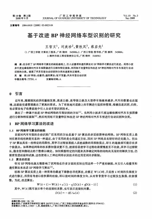
基于改进BP神经网络车型识别的研究
B P网络学 习算法 的改进
11 B . P网络 学 习算法 的缺 陷
目前对汽车车型的自动识别广泛采用 的方法是基于 B P算法 的多层前馈神经网络 。B P网络实质上是 对任意非线性映射关系的一种逼近, 由于采用的是全局逼近方法 , 因而 B P网络具有较好 的泛化能力。但 由 于B P算法具有一些特定的局限性 , 其学习过程容易陷入误差函数的局部极值点 , E的超曲面可能存在多 即
M2( ,) √l z =
( )
( ,) +1 z l z I ( ,) wi
en a( )
() 3
() 4
其中 V ( 和 w; ( ,) ,) z 分别为原图 像的水平和垂直方向的边缘信息。
若图像 厂 , 二阶小波变换的局部极值点是点( , )在该点上 , ( ) , 则沿着由 A2 , 给定 的梯度 ( ) 方向上的 w2 , ) ( 为局部最大 , 即在尺度为 2 时, 图像 厂 , 的灰度突变点对 应于沿梯度方 向的 ( ) ( ) z , 局部极大值。这些取极大值点 的位置就给出了图像的一个多尺度边缘。通过对不 同种类车型 的识别结果表明, 这种基于小波变换模局部极大值的多尺度边缘检测方法 , 能够较好地检测出所有车型的轮 廓信息 , 是一种 比较有效的边缘检测方法 , 为后续 的车型特征值的提取和分类打下了良好的基础 。 2 2 车型 的特 征提取 和识 别 .
摘
要: 在分析 了 B P网络学习算 法的缺陷基础上 , 引入动 量项和遗传 算法对 B P网络学习算法进行改进 。利用小波
多尺度边缘检测对汽车车型图像进行分 割和特征提取 , 利用矩不变量特征 和改进 B P神经 网络对 汽车车型进 行 自动
识别 和分类 。提高了汽车车型 自 动识别 和分 类的速度和正 确率 。 关 键 词 :P网络 ; B 动量项 ; 遗传算法 ; 矩不变量 ; 汽车车 型 自动识 别
基于深度卷积-长短期记忆神经网络的整车道路载荷预测
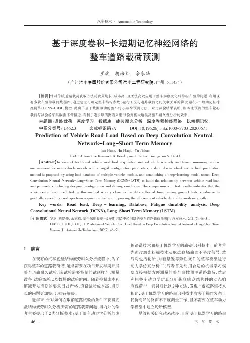
拟路谱技术和基于机器学习的路谱识别技术。前者首 先通过激光扫描技术获取试验场路面不平度信号,然 后对包括轮胎、衬套悬置等弹性元件的整车模型进行 动力学仿真分析 ;后 [1-4] 者首先利用合适的机器学习模 型直接根据方便测量的整车参数预测道路载荷,然后 利用整车动力学仿真分析获取底盘结构件的动态响 应载荷 。 [5-8] 通过对比这 2 种方法,发现与虚拟路谱技术 相比,基于机器学习的路谱识别技术省去了操作复杂且 代价高昂的路面不平度测量工作,且不需要在整车动力 学模型中建立轮胎模型。
经 网 络(DCNN-LSTM)模 型 ,提 出 了 基 于 数 据 驱 动 的 整 车 轮 心 载 荷 预 测 方 法 。 对 比 试 验 结 果 表 明 ,该 方 法 预 测 的 整 车 轮 心
载荷与试验场采集数据非常接近,有利于逐步取消路谱采集试验并极大地提高整车耐久性分析的效率。
主题词:道路载荷 深度学习 数据库 疲劳耐久分析 深度卷积神经网络 长短期记忆
每小块求取统计值(如均值或最大值)即可得到池化层 的输出信息。在整车道路载荷预测中,需要处理的汽车
算和求和运算,然后通过非线性转换获得卷积层的输出 信息。在池化层,输入的数据被分为很多小块,通过对
运行参数属于一维时序数据,因此 DCNN 层选用如图 2 所示的一维卷积神经网络层。
x(1) x(2)
x(S - 1) x(S)
1 前言
在现有的汽车底盘结构疲劳耐久分析流程中,为了 获得整车的道路载荷谱,通常需要在项目开发早期开展 整车道路耐久试验,该试验需要特制的试制样车、测量 设备、试验场所以及数周的试验时间。随着控制成本和 缩减开发周期的要求日益严格,道路试验成本高、周期 长的问题更加突出,亟待解决。
基于深度神经网络的驾驶行为识别研究

基于深度神经网络的驾驶行为识别研究随着科技的快速发展,深度学习技术得以逐步普及和应用到诸多领域中,其中非常重要的一个领域就是自动驾驶技术,而驾驶行为识别作为其中的关键技术之一,其应用不仅有助于提高自动驾驶的安全性和可靠性,而且还有助于提高人类驾驶者的驾驶技能和安全意识。
本文旨在探讨基于深度神经网络的驾驶行为识别研究,介绍其相关技术和应用,并分析其存在的问题和未来的发展方向。
一、深度神经网络简介深度神经网络,也称作深度学习,是一种基于神经网络的机器学习技术,其由多个隐藏层组成,可以自动地提取和学习数据的复杂特征,并用于分类、回归等领域。
在自然语言处理、计算机视觉、语音识别等领域中已经得到广泛应用,并呈现出极强的表现性能。
其中,在驾驶行为识别领域的应用也逐渐得到拓展和普及,被广泛运用于自动驾驶技术、智能设备等领域。
二、基于深度神经网络的驾驶行为识别技术基于深度神经网络的驾驶行为识别技术,主要通过分析驾驶员的行为特征,来判断其当前的驾驶状态和行为意图。
这种技术可以通过对驾驶员的生理数据、车辆数据等多种类型数据的采集和处理,来识别和分析驾驶员的驾驶行为,从而实现对驾驶员状态的自动检测和分析。
该技术在驾驶员监控、安全驾驶等多个领域上具有广泛的应用前景。
1.驾驶行为特征提取驾驶行为特征提取是基于深度神经网络的驾驶行为识别技术的关键环节之一。
该技术通过对驾驶员的行为数据进行分析、特征提取和特征下采样等操作,来实现对驾驶员行为特征的高效提取和学习。
其中,驾驶员的生理数据和车辆传感器数据是提取驾驶行为特征的重要数据源。
通过对这些数据源的数据进行处理和分析,就可以提取出驾驶员的驾驶行为特征,包括车速、方向盘转角、行驶路径等。
2.驾驶行为分类基于深度神经网络的驾驶行为识别技术,主要通过对驾驶员行为的分类和判断,来确定当前的驾驶状态和行为意图。
该技术可以通过多种分类算法的组合和优化,来实现对驾驶员驾驶行为的高效分类和识别。
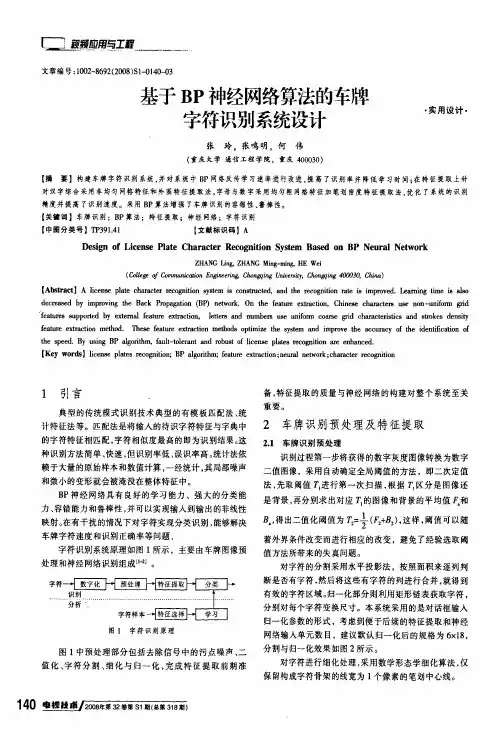
基于BP神经网络算法的车牌字符识别系统设计(精品)
[:j型蜒曰墅霹麓………。
文章编号:1002—8692(2008)S1-0140—03基于B P神经网络算法的车牌字符识别系统设计张玲,张呜明,何伟(重庆大学通信工程学院,重庆400030)·实用设计·【摘要】构建车牌字符识别系统,并对系统中B P网络反传学习速率进行改进,提高了识别率并降低学习时间;在特征提取上针对汉字综合采用非均匀网格特征和外围特征提取法,字母与数字采用均匀粗网格特征加笔划密度特征提取法。
优化了系统的识别精度并提高了识别速度。
采用B P算法增强了车牌识别的容错性、鲁棒性。
【关键词】车牌识别;B P算法;特征提取;神经网络;字符识别【中图分类号】TP391.41【文献标识码】AD es i gn of L i cens e Pl at e C ha r act er R ecogn i t i on Syst e m B a se d o n B P N e ur a l N et w or kZ H A N G L i n g,Z H A N G M i ng-m i ng,H E W e i(Co l l ege of C om m uni c at i on E ng i neer i ng,C ho ngqi ng U ni ve rs饥C hongqi ng400030,C hi na)【A bs t ra ct】A l i cens e pl at e cha r act er r ecogni t i on sys t em i s con st r uc t ed,a nd t he r ecogni t i on r a te i s i m pr o ved。
Lear ni n g t i m e i s als o de cr ea sed by i m pr ov i ng t he B ack Propagat i on(B P)net w ork.O n t he f eat ur e ext r act i on,C h i nese char act er s non—uni f orm鲥d 。
智能车辆中英文对照外文翻译文献
中英文对照外文翻译文献(文档含英文原文和中文翻译)原文:Intelligent vehicle is a use of computer, sensor, information, communication, navigation, artificial intelligence and automatic control technology to realize the environment awareness, planning decision and automatic drive of high and new technology. It in aspects such as military, civil and scientific research has received application, to solve the traffic safety provides a new way.With the rapid development of automobile industry, the research about the car is becoming more and more attention by people. Contest of national competition and the province of electronic intelligent car almostevery time this aspect of the topic, the national various universities are also attaches great importance to research on the topic, many countries have put the electronic design competition as a strategic means of innovative education. Electronic design involving multiple disciplines, machinery and electronics, sensor technology, automatic control technology, artificial intelligent control, computer and communication technology, etc., is a high-tech in the field of many. Electronic design technology, it is a national high-tech instance is one of the most important standard, its research significance is greatThe design though just a demo model, but is full of scientific and practical. First we according to the complex situation of road traffic, in accordance with the appropriate author to make a road model, including bend, straight and pavement set obstacles, etc. On curved and straight, the car along the orbit free exercise, when the small car meet obstacles, pulse modulation infrared sensors to detect the signal sent to the microcontroller, a corresponding control signal according to the program MCU control cars automatically avoid obstacles, to carry on the back, forward, turn left, turn rightSubject partsIntelligent vehicle is a concentration of environment awareness, planning decision, multi-scale auxiliary driving, and other functions in an integrated system, is an important part of intelligent transportation system.In military, civilian, space exploration and other fields has a broad application prospect. The design of smart car control system are studied, based on path planning is a process of the intelligent car control system2.1 theory is put forwardThe progress of science and technology of intelligent led products, but also accelerated the pace of development, MCU application scope of its application is increasingly wide, has gone far beyond the field of computer science. Small to toys, credit CARDS, big to the space shuttle, robots, from data acquisition, remote control and fuzzy control, intelligent systems with the human daily life, everywhere is dependent on the single chip microcomputer, this design is a typical application of single chip microcomputer. This design by implementing the driverless car, on the tests, by the reaction of the single chip microcomputer to control the car, make its become intelligent, automatic forward, turn and stop function, after continuing the perfection of this system also can be applied to road testing, security patrol, can meet the needs of society.In design, the use of the sensors to detect road surface condition, sensor central sea are faint and adopts a comparing amplifier amplification, and the signal input to the controller, the controlled end using stepper motor, because of the step motor is controlled electrical pulse, as long as the output from the controller to satisfy stepper motor merits of fixed control word. In operation of stepping motor and a drivingcircuit, it also to join a drive circuit in the circuit, each function module is different to the requirement of power supply current, the power supply part set up conversion circuit, so as to meet the needs of the various parts. After comparison choice element, design the circuit principle diagram and the circuit board, and do the debugging of hardware, system software and hardware is often the combination of organic whole. Software, on the use of the 51 single-chip timer interrupt to control pavement test interval and the car movement and speed. Due to take that road is simple, it is using more traditional assembly language for programming. For the correctness of the program design, using a commonly used keil c51 simulation software simulation validation, the last is integrated debugging of software and hardware, and prove the correctness and feasibility of the design scheme.2.2 electronic intelligent car design requirements(1) electric vehicles can be able to according to the course to run all the way; (2) electric vehicles can store and display the number of detected metal and sheet metal to the starting line in the distance; (3) are accurately electric cars after exercising all the way to the display of the electric vehicle the entire exercise time; (4) electric cars can't collisions with obstacles in the process of exercise.2.3 the general conception of computer network teaching websiteUsing 89 c51 as the car's control unit, sensor eight-way from outside,in the front of the car, as a black belt in the process of the car into the garage detecting element, at the rear end of the car when connected to eight-channel infrared sensors as the car pulled out of the garage of a black belt in detecting element, the LJ18A3-8 - Z/BX inductive proximity switch as garage iron detecting element, the microcontroller after receiving sensor detects the signal through the corresponding procedures to control the car forward, backward, turn, so that the car's performance indicators meet the requirements of the design.Intelligent car is a branch of intelligent vehicle research. It with the wheel as mobile mechanism, to realize the autonomous driving, so we call it the smart car. Smart car with the basic characteristics of the robot, easy to programming. It with remote control car the difference is that the latter requires the operator to control the steering, start-stop and in a more advanced remote control car can also control the speed (common model car belong to this type of remote control car); The smart car Is to be implemented by computer programming for the car stop, driving direction and speed control, without human intervention. Operator the smart car can be changed by a computer program or some data to change its drive type. This change can be controlled through programming, the characteristics of the car driving way is the biggest characteristic of smart car. The control system of smart car research purpose is to make the car driving with higher autonomy. If any given car a path, through the system,the car can get system for path after image processing of data moving and Angle (a), and can be scheduled path, according to the displacement and Angle information.The control system structure analysisAccording to the above design idea, the structure of the intelligent car control system can be divided into two layers1, the planning layerPC control system, the planning layer provides the information of the whole car driving, including path processing module and communication module. It has to solve the basic problem(1) using what tools to deal with the car path graph;(2) the car movement model is established, the data to calculate the car driving;(3) set up the car's motion model, the data to calculate the car driving;Layer 2, behaviorLower machine control system, the behavior is the underlying structure of a smart car control system, realize the real-time control of the car driving, it includes communication module, motor control module and data acquisition module. It to solve the basic problems are:(1) receiving, processing, PC sends data information;(2) the design of stepping motor control system;(3) information collection and the displacement and Angle of the car, car positioning posture, analysis system control error;The total design schemeSmart car control system are obtained by system structure, order process:(1) start AutoCAD, create or select a closed curve as the cart path, pick up the car starting $path graph(2) to choose the path of the graphics processing, make the car turning exist outside the minimum turning radius of edges and corners with circular arc transition(3) to generate a new path to simulate the motion process of car;(4) to calculate the displacement of the car driving need and wheel Angle, and then sends the data to the machine(5) under the machine after receiving data, through software programming control the rotation speed and Angle of the car wheels and make it according to the predetermined path A complete control system requirements closely linked to each function module in the system, according to the order process and the relationship between them, the total design scheme of the system is available.Design of basically has the following several modulesPart 1, the information acquisition module, data collection is composed of photoelectric detection and operation amplifier module,photoelectric detection were tracing test and speed test of two parts. To detect the signal after budget amplifier module lm324 amplifier plastic to single chip, its core part is several photoelectric sensor.2, control processing module: control processing module is a stc89c52 MCU as the core, the microcontroller will be collected from the information after the judgement, in accordance with a predetermined algorithm processing, and the handling results to the motor drive and a liquid crystal display module, makes the corresponding action.3, perform module: executable module consists of liquid crystal display (LCD), motor drive and motor, buzzer of three parts. LCD is mainly based on the results of single chip real-time display, convenient and timely users understand the current state of the system, motor driver based on single chip microcomputer instruction for two motor movements, can according to need to make the corresponding acceleration, deceleration, turning, parking and other movements, in order to achieve the desired purpose. Buzzer is mainly according to the requirements in a particular position to make a response to the report.译文一、引言智能车辆是一个运用计算机、传感、信息、通信、导航、人工智能及自动控制等技术来实现环境感知、规划决策和自动行驶为一体的高新技术综合体。
基于BP分类器的数字识别研究
基于BP分类器的数字识别研究作者:李恩佳高庆敏李慧朱娟来源:《科技创新导报》2011年第27期摘要:本文通过分析BP(Back Propogation)神经网络的结构、原理及其算法,对已经经过预处理的图像进行分析和识别,使分类器能够对0~9之间的数字在最短的时间进行准确分类,从而达到识别出图片中的数字。
系统既可以单独使用,也可以作为一个识别系统的软件核心应用到大规模数据统计、财务、税金、金融和车牌识别等系统中。
关键词:BP神经网络数字识别BP算法分类中图分类号:TP391.4 文献标识码:A 文章编号:1674-098X(2011)09(c)-0109-01引言人工神经网络,即从生物学神经系统的信号传递而抽象发展而成的一门科学。
它是一个高度并行、非线性、具有很高冗余度的系统,其结构特点使知识的表达与存储,都与传统的方法有很大的不同。
本文采用BP神经网络进行数字识别。
利用神经网络极强的非线性的数据处理能力、良好的容错能力和自学习能力等,通过大量的样本进行的网络训练,最终得到以识别的数字输出。
1 BP(Back Propagation)神经网络人工神经网络是从生物学神经系统的信号传递而抽象发展而成的一门科学。
在神经网络中,最基本的单元就是神经元。
神经元由三部分组成:树突、细胞体和轴突。
树突是树状的神经纤维接受网络,它将电信号传递给细胞体。
轴突是单根长纤维,它把细胞体的输出信号导向其他的神经元。
神经元的排列拓扑结构和突触的连接强度确立了神经网络的功能。
形象的说,神经网络是由大量处理单元广泛连接而成的网络,是对人脑的抽象、简化和模拟、反映人脑的基本特征。
它能够通过学习过程从外部环境中获取知识,并且它内部的神经元可以存储这些已经学到的知识。
BP网络是前向网络的一种,是典型的多层前馈网络,在多层网络中,一般有三个层次:一个输入层、一个输出层、一个或多个隐层。
神经元网络模型用于模拟人脑神经元活动的过程,包括对信息的加工、处理、存储和搜索的等的过程。
Intelligent Vehicles
Steve Shladover outlines the benefits to be gained from vehicles ['vi??k(ə)l] that could drive themselves and discusses how this could be achieved.斯蒂夫·施多弗阐述了能自动运行的车辆的诸多裨益,并详细论述了如何将其变为现实。
Intelligent Vehicles [in'telidʒent] Steve Shladover1 Even when cars were still young, futurists ['fju:tʃərist] began thinking about vehicles that could drive themselves, without human help. Perhaps the best known of these conjectures [kən'dʒektʃə] was the General Motors Futurama[,fju:tʃə'ræmə], the hit of the 1939 New York World's Fair[fεə] . Now, at the start of the new century, it's worth taking a fresh look at this concept and asking how automation might change transportation and the quality of our lives.[laivz]Fair[fεə]n. 展览会;市集;美人adj. 公平的;美丽的,白皙的;[气象] 晴朗的adv. 公平地;直接地;清楚地网络释义:公平的集市交易会fresh [freʃ] n. 开始;新生;泛滥adj. 新鲜的;清新的;淡水的;无经验的adv. 刚刚,才;最新地网络释义:新鲜的清新的鲜艳的concept ['kɔnsept] n. 观念,概念智能车辆斯蒂夫·施多弗还在汽车问世之初,未来学家就开始设想无需人来操纵便能自动运行的车辆将是什么样儿的。
车型识别综述
车型识别综述一.课题的背景和意义智能交通系统(ITs,IntelligentTransportationSystem)是集计算机、信息、电子及通信等多种高新科技手段于一体的交通控制和管理系统,是21世纪交通的重要发展方向。
智能交通系统中的核心功能是对过往车辆的准确检测和正确的车型识别。
当前对车辆检测分类技术的研究主要有两个技术流派:车辆自动识别(Auto Ve hlcle Identification)和车辆自动分类(AutoVehicle Classification)。
前者是利用车载设备与地面基站设备互识进行,该技术主要用于收费系统中,在发达国家使用范围较广,如美国[2]的AE-PASS系统、日本的ETC系统,全球卫星GPS定位等。
后者是通过检测车辆本身固有的参数,在一定车辆分类标准下运用适当的分类识别算法,主动地对车辆进行分型,这一类技术应用比较广泛,己经有很多成熟的系统应用在实际生活中,该类技术可以通过射频微波、红光、激光、声表面波等方式来自动识别车辆信息,也可以使用视频图像处理的方式来识别车牌、车型等车辆信息。
比较成熟技术有环形线圈检测、激为红外线检测、超声波/微波检测、地磁检测等[3],但这几种方法各有优劣,优点是识别精确比较高,但缺点也很明显,主要缺点有施工和安装过程十分复杂,影响正常交通秩序,维护困难,主要设备易损坏,花费较大等。
近年来随着计算机多媒体技术和图像处理技术的发展,基于视频的车辆自动分类识别技术在现代交通控制系统中占的分量也越来越大,社会各界投入的研究力量也越来越多。
该类技术可以适应动态交通状况的变化,通过实时采集大量的交通流量数据并将其传输到交通管理中心,中心通过系统提供的数据可以迅速做出控制决策,解决交通拥堵等问题。
同时,利用该技术可以分析道路的车流量信息,有利于公路网的总体规划及道路建设。
但上述功能的实现依赖于交通数据的采集和处理,传统的数据采集器方法,不能大范围覆盖检测区域,缺乏灵活性且功能单一。
- 1、下载文档前请自行甄别文档内容的完整性,平台不提供额外的编辑、内容补充、找答案等附加服务。
- 2、"仅部分预览"的文档,不可在线预览部分如存在完整性等问题,可反馈申请退款(可完整预览的文档不适用该条件!)。
- 3、如文档侵犯您的权益,请联系客服反馈,我们会尽快为您处理(人工客服工作时间:9:00-18:30)。
、外文资料License Plate Recognition Based On Prior KnowledgeAbstract - In this paper, a new algorithm based on improved BP (back propagation) neural network for Chinese vehicle license plate recognition (LPR) is described. The proposed approach provides a solution for the vehicle license plates (VLP) which were degraded severely. What it remarkably differs from the traditional methods is the application of prior knowledge of license plate to the procedure of location, segmentation and recognition. Color collocation is used to locate the license plate in the image. Dimensions of each character are constant, which is used to segment the character of VLPs. The Layout of the Chinese VLP is an important feature, which is used to construct a classifier for recognizing. The experimental results show that the improved algorithm is effective under the condition that the license plates were degraded severely.Index Terms - License plate recognition, prior knowledge, vehicle license plates, neural network.I. INTRODUCTIONVehicle License-Plate (VLP) recognition is a very interesting but difficult problem. It is important in a number of applications such as weight-and-speed-limit, red traffic infringement, road surveys and park security [1]. VLP recognition system consists of the plate location, the characters segmentation, and the characters recognition. These tasks become more sophisticated when dealing with plate images taken in various inclined angles or under various lighting, weather condition and cleanliness of the plate. Because this problem is usually used in real-time systems, it requires not only accuracy but also fast processing. Most existing VLP recognition methods [2], [3], [4], [5] reduce the complexity and increase the recognition rate by using some specific features of local VLPs and establishing some constrains on the position, distance fromthe camera to vehicles, and the inclined angles. In addition, neural network was used to increase the recognition rate [6], [7] but the traditional recognition methods seldom consider the prior knowledge of the local VLPs. In this paper, we proposed a new improved learning method of BP algorithm based on specific features of Chinese VLPs. The proposed algorithm overcomes the low speed convergence of BP neural network [8] and remarkable increases the recognition rate especially under the condition that the license plate images were degrade severely.II. SPECIFIC FEATURES OF CHINESE VLPSA. Dime nsionsAccord ing to the guideli ne for vehicle in spect ion [9], all lice nse plates must be recta ngular and have the dimensions and have all 7 characters written in a single line. Under practical environments, the distanee from the camera to vehicles and the inclined angles are constant, so all characters of the license plate have a fixed width, and the distanee between the medium axes of two adjoining characters is fixed and the ratio between width and height is nearly con sta nt. Those features can be used to locate the plate and segme nt the in dividual character.B. Color collocati on of the plateThere are four kinds of color collocati on for the Chin ese vehicle lice nse plate .These color collocatio ns are show n in table I.Moreover, military vehicle and police wag on plates contain a red character which bel ongs to a specific character set. This feature can be used to improve the recog niti on rate.C. Layout of the Chi nese VLPSThe criteri on of the vehicle lice nse plate defi nes the characters layout of Chin ese lice nse plate. All sta ndard lice nse plates contain Chin ese characters, nu mbers and letters which are shown in Fig.1. The first one is a Chinese character which is an abbreviation of Chinese provinces. The second one is a letter ranging from A to Z except the letter I. The third and fourth ones are letters or nu mbers. The fifth to seve nth ones are nu mbers ranging from 0 to 9 only. However the first or the seve nth ones may be red characters in special plates (as show n in Fig.1). After segme ntatio n process the in dividual character is extracted. Taking adva ntageof the layout and color collocati on prior kno wledge, the in dividual character will en ter one of the classes: abbreviati ons of Chin ese provi nces set, letters set, letters or nu mbers set, nu mber set, special characters set.Chin ese character(b) Special characterFig.1 The layout of the Chin ese lice nse plateIII. THE PROPOSED ALGORITHMThis algorithm consists of four modules: VLP location, character segmentation, character classification and character recognition. The main steps of the flowchart of LPR system are show n in Fig. 2.Firstly the lice nse plate is located in an in put image and characters are segme nted. The n every in dividual character image en ters the classifier to decide which class it bel ongs to, and fin ally the BP n etwork decides which character the character image represe nts.(a)Typical layoutFig.2 The flowchart of LPR systemA. Preprocess ing the lice nse plate1) VLP Locati onThis process sufficie ntly utilizes the color feature such as color collocati on, color cen ters and distributi on in the plate regi on, which are described in sect ion II. These color features can be used to eliminate the disturbance of the fake plate ' s regions. The flowchart of the plate locati on is show n in Fig. 3.The regions which structure and texture similar to the vehicle plate are extracted. Theprocess is described as followed:Here, the Gaussia n varia nce is set to be less tha n W/3 (W is the character stroke width), so R gets its maximum value M at the center of the stroke. After convolution, binarization is performed according to a threshold which equals T * M (T<0.5). Median filter is used to preserve the edge gradie nt and elimi nate isolated no ise of the bi nary image. An N * N recta ngle median filter is set, and N represents the odd integer mostly close to W.Morphology clos ing operati on can be used to extract the can didate regi on. The con fide nce degree of can didate regi on for being a lice nse plate is verified accord ing to the aspect ratio and areas. Here, the aspect ratio is set between 1.5 and 4 for the reason of inclination. The prior kno wledge of color collocati on is used to locate plate regi on exactly. The locat ing process of the lice nse plate is show n in Fig. 4.P x >thelse (1)⑵Fig.3 The flowchart of the plate location algorithm2) Character segme ntati onThis part presents an algorithm for character segmentation based on prior knowledge, usingcharacter width, fixed nu mber of characters, the ratio of height to width of a character, and so on. The flowchart of the character segmentation is shown in Fig. 5.Firstly, preprocess the lice nse the plate image, such as uneven illu min ati on correct ion, contrast enhan ceme nt, in cli necorrect ion and edge enhan ceme nt operati ons; sec on dly, elim in at ing space mark which appears betwee n the sec ond character and the third character;thirdly, merging the segmented fragments of the characters. In China, all standard license plates con tain on ly 7 characters (see Fig. 1). If the nu mber of segme nted characters is larger tha n seve n, the merging process must be performed. Table II shows the merging process. Fin ally, extracti ng the in dividual character ' image based on the nu mber and the width of the character. Fig. 6 shows the segmentation results. (a) The incline and broken plate image, (b) the incline and distort plate image, (c)the serious fade plate image, (d) the smut lice nse plate image.[vT【八"⑴小](f) Pl ate ex tt AC ting(e > Srinctiire veHtlcation Fig. 4 The whole process of locat ing lice nse plate(c)M ed inni filler i nfFig. 5 The flowchart of the character segme ntati onGet NfIf NF> MaxFFor each character segme ntsCalculate the medium point M iFor each two con secutive medium pointsCalculate the distanee D K Calculate the mi nimum dista nee Merge the character segme nt k and the character segme nt k +1 NF = NF - 1End of algorithmwhere Nf is the nu mber of character segme nts, MaxF is thenu mber of the lice nse plate, and i is the in dex of each character segme nt.The medium point of each segme nted character is determ ined by:(3)where is the in itial coord in ates for the character segme nt,and S i2 is the final coord in ate for the character segme nt. The dista nee betwee n two con secutive medium points is calculated by:(4)B. Using specific prior knowledge for recognitionThe layout of the Chin ese VLP is an importa nt feature (as described in the sect ion II),TABLEII+ ^2(u)Fig.6 Thesegme ntati on resultswhich can be used to con struct a classifier for recog nizing. The recog nizing procedure adopted conjugate gradie nt desce nt fast lear ning method, which is an improved lear ning method of BP neural network[10]. Conjugate gradient descent, which employs a series of line searches in weight or parameter space. One picks the first desce nt directi on and moves along that direct ion un til the minimum in error is reached. The sec ond desce nt direct ion is the n computed: this direct ion the “ conjugate direct ion ” is the one along which the gradie nt does not cha nge its direct ion will not “ spoil ” the con tributi on from the previous desce nt iterati ons. This algorithm adopted topology 625-35-N as show n in Fig. 7. The size of in put value is 625 (25*25 ) and in itial weights are with ran dom values, desired output values have the same feature with the in put values.Input X XI X2 … Xi …K625Fig. 7 The n etwork topologyAs Fig. 7 shows, there is a three-layer n etwork which contains worki ng sig nal feed forward operati on and reverse propagati on of error processes. The target parameter is t and the len gth of n etwork output vectors is n. Sigmoid is the non li near tran sfer fun cti on, weights are in itializedwith ran dom values, and cha nged in a directi on that will reduce the errors.The algorithm was trained with 1000 images of differe nt backgro und and illu min ati on most of which were degrade severely. After preprocess ing process, the in dividual characters are stored. All characters used for training and test ing have the same size (25*25 ).The in tegrated process for lice nse plate recog niti on con sists of the follow ing steps:1) Feature extract ingThe feature vectors from separated character images have direct effects on the recog niti on rate. Many methods can be used to extract feature of the image samples, e.g. statistics of data at vertical directi on, edge and shape, framework and all pixels values. Based on exte nsive experime nts, all pixels values method is used to con struct feature vectors. Each character was reshaped into a column of 625 rows ' feature vector. These feature vectors are divided into two categories which can be used for training process and testing process.2) Training modelThe layout of the Chin ese VLP is an importa nt feature, which can be used to con struct aclassifier for training, so five categories are divided. The training process of nu mbers is show n in Fig. 8.As Fig. 8 shows, firstly the classifier decides the class of the in put feature vector, and the n(a) Training process(b)Test ing processFig.9 The recog niti on processthe feature vector enters the neural network correspondingly. After the training process theoptimum parameters of the net are stored for recog niti on. Thetraining and testi ng process issummarized in Fig. 9. i n pulfknluixvectorFig. 8 The architecture of a n eural n etwork for character recog nition3) Recog nizing modelAfter training process there are five n ets which were completely trained and the optimum parameters were stored. The untrained feature vectors are used to test the n et, the performa nee of the recognition system is shown in Table III. The license plate recognition system is characterized by the recog niti on rate which is defi ned by equati on (5).Recognition rate =(number of correctly read characters) / (number of found characters) (5)TABLE IIIIV. COMPARISON OF THE RECOGNITION RATE WITH OTHER METHODS In order to evaluate the proposed algorithm, two groups of experime nts were con ducted.One group is to compare the proposed method with the BP based recog niti on method [11]. The result is show n in table IV. The other group is to compare the proposed method with the method based on SVM [12].The result is show n in table V. The same training and test data set are used. The comparis on results show that the proposed method performs better tha n the BP n eural n etwork and SVM coun terpart.In this paper, we adopt a new improved learning method of BP algorithm based on specificfeatures of Chinese VLPs. Color collocation and dimension are used in the preprocessing procedure, which makes location and segmentation more accurate. The Layout of the Chinese VLP is an important feature, which is used to construct a classifier for recognizing and makes the system performs well on scratch and inclined plate images. Experimental results show that the proposed method reduces the error rate and consumes less time. However, it still has a few errors when dealing with specially bad quality plates and characters similar to others. This often takes place among these characters (especially letter and number):3 —8 4—A 8—B D —0. In order to improve the incorrect recognizing problem we try to add template-based model [13] at the end of the neural network.REFERENCES[1] P. Davies, N. Emmottand N. Ayland ,“ License Plate Recognition Technology for Toll Violation Enforcement ” Proceedings of IEE Colloquium on Image analysis for Transport Applications , Vol . 035, pp. 7/ 1- 7/5, February 16, 1990.[2] V. Koval , V. Turchenko, V . Kochan, A. Sachenko, G. Markowsky , “Smart. License Plate Recognition System Based on Image Processing Using Neural Network ” IEEE International Workshop on Intelligent Data Acquisition and Advanced Computing System: Technology Applications 8- 10 September 2003.[3] Abdullah , S.N.H. S.; Khalid , M. ;Yusof , R.; Omar, K. “ License Plate Recognition using multi - cluster and Multilayer Neural Networks ” Information and Communication Technologies, 2006. ICTTA ' 06. 2nd Volume 1, 24-28 April 2006 Page( s): 1818 - 1823.[4] Nathan, V.S. L.; Ramkumar, J.; Kamakshi Priya, S. “ New approaches for license plate recognition system” Intelligent Sensing and Information Processing, 2004. Proceedings of International Conference on 2004 Page(s): 149 - 152.[5] Mei Yu; Yong Deak Kim , “ An approach to Korean license plate recognition based on vertical edge matching” Volume 4, 8-11 Oct. 2000 Page(s): 2975 - 2980 vol.4.[6] Tindall, D.W. ” Application of neural network techniques to automatic licence platerecognition ” Security and Detection, 1995., European Convention on 16-18 May 1995 Page(s): 81 - 85.[7] Aghdasi, F.; Ndungo, H. “Automatic licence plate recognition system” AFRICON , 2004. 7th AFRICON Conference in AfricaVolume 1, 2004 Page(s): 45 - 50 Vol. 1[8] Richard O. Duda Peter E.Hart David G.Stork, “Pattern Classification Second Edition ”PP 333 - 373.[9] Standard for vehicle license plate number in the People' s Republic of China (GA 36- 92).[10] Richard O. Duda Peter E. Hart David G. Stork, “ Pattern Classification Second Edition ” PP 373 - 376.[11] Nukano , T.; Fukumi , M. ;Khalid , M.; “ Vehicle license plate character recognition by neural networks ” Intelligent Signal Processing and Communication Systems, 2004. ISPACS 2004. Proceedings of 2004 International Symposium on18- 19 Nov. 2004 Page( s): 771-775.[12] Xiaojun Chi; Junyu Dong ; Aihua Liu; Huiyu Zhou, “ A Simple Method for Chinese License Plate Recognition Based on Support Vector Machine ” Communications , Circuits and Systems Proceedings, 2006 International Conference on Volume 3, June 2006 Page( s): 2141 - 2145.[13] Yo- Ping Huang;Shi- Yong Lai ;Wei- Po Chuang, A template- based model for license plate recognition ” Networking , Sensing and Control , 2004 IEEE International Conference on Volume 2, 2004 Page( s): 737 - 742 Vol .2.二、译文基于先验知识的车牌识别摘要-本文基于一种新的改进的BP (反向传播)神经网络算法对中国的车辆车牌识别(LPR)进行了介绍。