SiC泡沫/Al双连续相复合材料连续性的研究
泡沫铝复合材料的研究
泡沫铝复合材料的研究泡沫铝复合材料的研究/刘欣等?79?泡沫铝复合材料的研究刘欣,薛向欣,张瑜,张淑会,段培宁,张虎(东北大学材料与冶金学院硼资源生态化综合利用技术与硼材料重点实验室,沈阳110004)摘要泡沫铝材料具有优越的综合性能,已被广泛应用于各个领域.系统阐述了国内外泡沫铝材料的应用现状,指出泡沫铝材料复合化是进一步完善其结构与功能的有效途径,并在此基础上详细介绍了国内外泡沫铝复合材料的研究情况.关键词泡沫铝性能应用复合材料中国分类号:TB383;TG146.2;TB34 StudyonAluminiumFoamsCompositesLIUXin,XUEXiangxin,ZHANGYu,ZHANGShuhui,DUANPeining,ZHANGHu (LiaoningKeyLabforEcologicallyComprehensiveUtilizationofBoronResource& MaterialsinSchoolofMaterialsandMetallurgy,NorthestemUniversity,Shenyang110004) AbstractAluminiumfoamsmaterialsarealreadyusedinvariousfieldswidlybecauseofitsex cellentcombi—nationproperty.Theinternalandoverseasapplicationstatusofaluminiumfoamsisdescribed systematicallyinthepa—per.Theavailableapproachisputforwardtoperfectthestructureandfunctionofaluminiumfo amsthroughpreparingaluminiumfoamscomposities.Andonthebasementionedabove,theresearchesaboutthealu miniumfoamscompositearepresenteddetailedly.Keywordsaluminiumfoams,performance,application,composities 0引言1?1多孔泡沫金属材料由金属骨架及孔隙所组成[】-z],是近几十年发展起来的一种功能材料.自问世以来,作为结构材料,它具有轻质,高比强度的特点;作为功能材料,它具有多孔,减振, 阻尼,吸音,隔音,散热,吸收冲击能,电磁屏蔽等多种物理性能, 兼之其可回收的特点,适应了当前发展的需要,在国内外一般工业领域及高技术领域得到了越来越广泛的应用[3川].目前已研制出的多孔泡沫金属材料有泡沫铝(及泡沫铝合金),泡沫镍,泡沫锌,泡沫铅,泡沫钛,泡沫铸铁及泡沫钢等,其中泡沫铝的研究最为成熟,并在实际应用中展现出广阔的前景L9.10J.我国对泡沫铝的研究始于2O世纪8O年代,起步较晚,在结构特征,制备工艺,性能研究等方面略落后于世界水平但是,针对泡沫铝材料自身的缺陷,以及其未来的发展趋势,国内研究者尝试研制出各种新型的泡沫铝复合材料,并取得了很好的成果.1泡沫铝的应用研究自1956年泡沫铝问世以来,人们对泡沫铝的结构特征,制备工艺,力学性能及其各种功能展开了深入全面的研究,已取得实质性进展,相关理论也较为成熟.在此基础上,人们利用泡沫铝优越的综合性能,即相对优异的力学性能,高阻尼性能,抗冲击性能,声学性能,热物理性能,渗透性能及电磁屏蔽性能等,在不同场合加以选择使用r.刘欣:女,1978年生,博士研究生E-mail;*******************泡沫铝在结构材料方面的应用泡沫铝具有一定的强度,延伸率和]jn-r性能,可用于结构材料,目前多用在交通运输,航空工业以及建筑工业_2"].泡沫铝可以用作汽车以及铁路运输车辆的缓冲部件,尤其是在汽车制造业上的应用,被认为是一种大有前途的未来汽车与其它交通运输工具的良好材料.轻质,高刚度且有吸能和隔音性能的泡沫铝已在汽车上得到应用,如顶盖板,底盖板和滑动顶板等高刚度构件C2,14~16].在航空领域,泡沫铝一般用作轻质, 传热的支撑结构,如机翼金属外壳的支撑体,导弹的防外壳高温坍塌支撑体,雷达的反射材料等.在建筑领域,泡沫铝一般用于制造质量轻,硬度高,有耐火性能要求的元件或构件l_1.叫引. 1.2泡沫铝在功能材料方面的应用因泡沫铝具有如高阻尼性能(吸声减震),冲击能吸收性能,优良的热物理性能(耐高温强热),电磁屏蔽等多种功能,令泡沫铝展现出广阔的应用前景L3"""l18].(1)利用高阻尼特性的领域.缓冲器及吸震器是泡沫铝的重要用途之一,其应用从汽车的防冲档直至宇宙飞船的起落架, 此外已被成功地用于升降机,传送器安全垫,高速磨床防护罩吸能内衬.泡沫铝轻质高阻尼性能特征,以及容易采取措施提高阻尼性能和结构加固的特点,使之特别适合高技术领域应用. (2)利用声学性能领域.开孔泡沫铝具有优异的声吸收能力,采用合适的声结构可以获得好的声吸收效果.日本已在高速列车发电机,无线电录音室及新干线吸音等多方面获得有应用前景的结果.泡沫铝还可用于消声减震方面l】.80材料导报2007年1月第21卷第1期(3)利用电磁屏蔽特征的领域.泡沫铝的电磁屏蔽性能可用于屏蔽,电磁兼容器件,根据需要可将其夹在塑料之间.(4)利用优异热物理性能的领域.开孔泡沫铝可以制作热交换器及散热器;闭孔泡沫铝可用作绝热材料,其强度及耐热能力优于相应的传统材料.作为一种新型的结构功能材料,泡沫铝材料已向人们展示了不可估量的应用前景,它的开发利用将对人类社会与科学技术的发展有着深远的意义.2泡沫铝的复合化研究目前,在实际应用中,人们为提高泡沫铝的功能特征常常以牺牲其力学性能为代价,同时由于泡沫铝生产成本高,性能可重现性差,使之无法有效地投入生产应用.针对这些问题,研究人员在致力于改善泡沫铝制备工艺,结构特征及综合性能的基础上,设计开发泡沫铝复合材料,充分发挥其质轻,多功能性的特点,使泡沫铝的推广应用得到保证.当前国内外泡沫铝复合材料的研究主要有以下几个方面.2.1泡沫铝层合结构为了充分发挥泡沫铝的各种特性,人们往往将其制成层合结构.与其它材料的层合结构相比,各种形式的泡沫铝层合结构具有耐热,各向同性,成本低等优势.在汽车,航空,航天,建筑等方面有着广泛的应用领域0.2.1.1泡沫铝三明治结构众所周知,泡沫铝最大的弱点就是强度不高,限制了它的应用领域.如果将它与传统的致密金属结合起来,组成夹芯构件使用将是其最有利的发展方向.泡沫铝夹芯结构基本上可分为夹芯板结构与填充管结构两种[2,目前应用较多的是泡沫铝夹芯板结构夹芯板结构是由金属面板与泡沫铝芯构成,即所谓的三明治结构,该结构具有轻质,高比刚度的特点,以及良好的减振(阻尼)性能,在充分发挥泡沫铝材料自身特点的同时解决了其强度低的问题,因此越来越受到研究者的重视r2.;这种泡沫铝三明治结构可以用很多方法生产,其中最简单最直接的方法是将预先制备好的泡沫材料和平板粘接在一起. 但胶黏部分不耐高温,易老化,很多情况下很不实用.另外就是采用以泡沫材料为芯的压铸方法.通过轧制一包覆工艺在发泡预制板上包覆面板,然后采用发泡的方法制备外表美观的泡沫铝三明治结构.现存的传统连接方法还有螺钉连接,铆接,钎焊,激光束焊接.但这些方法都是将制备完的中问发泡预制体或泡沫体裸板与面板进行连接I2q.当前泡沫铝三明治制备方法的研究热点是粉末冶金发泡法,该方法使面板与芯部达到冶金结合,有望克服不耐温,易老化等问题,图1为梁晓军等采用粉末冶金发泡法制备的铁面板/泡沫铝三明冶板_2.图1铁面板(1ram)/泡沫铝三明治结构Fig.1Ironplate(1mm)/Mumbfiumcoresandwichstructure[~].目前,泡沫铝材在汽车制造中的应用多为三明冶式结构.用三明治式泡沫铝材制造的某些汽车零件的质量只有原钢件质量的1/2,而其刚度却为钢件的10倍,绝热性能比铝高95,对频率大于800Hz的噪声有很强的消声能力.同时因泡沫铝材还是一种热稳定的不可燃材料,也是一种抗破坏的耐用材料,并可以完全回收与再生利用,被认为是一种大有前途的用于未来汽车与其它交通运输工具上的良好材料.德国卡曼汽车公司用三明治式复合泡沫铝材制造的"吉雅"轻便轿车(Ghiaroadster) 的项盖板的刚度达到原来钢构件的7倍左右,而其质量却比原钢件轻25.此外,其还具有更好吸收冲击能与声能的效果[.在航天工程中,同时具有多项优良性能的泡沫铝是理想的结构材料.在火箭实际运载能力有限的条件下,如能减轻结构质量,增加有效载荷则可以大大降低发射成本.如果把泡沫铝用在航天器上,经济效益将是显而易见的.美国波音公司对使用三明治式泡沫铝制造直升机的尾桁进行了评估,达到了理想的效果[3o]2.1.2泡沫铝复合板结构对于泡沫铝声学性能上的利用与完善多采用泡沫铝复合板结构.单一泡沫结构具有较好的吸音效果,但比不上玻璃纤维类传统吸音材料,特别是在低频(1000Hz)以下,其吸音系数要低得多.然而,可利用泡沫金属与其它吸音材料的组合,或从吸音结构上进行改进等方法获得高性能吸音器,如AISi.泡沫+玻璃纤维+空气垫的组合就表现出了优越的吸音特性r3.另外通过热处理工艺研制的氧化铝陶瓷和泡沫铝合金的夹层复合板可以提高陶瓷的抗冲击能力【3.];用热压固化法制备的泡沫铝/树脂/铝合金叠层复合材料的界面结合良好,弯曲强度达300MPa左右,具有优良的冲击性能和阻尼吸振性能【3.总之,为了充分发挥泡沫铝材料的性能,更多的泡沫铝层合结构正在研制开发中,以适应社会不断发展的各种需求.2.2填充高分子材料的泡沫铝复合材料泡沫铝具有一系列独特的性能,特别是它所具备的高阻尼性能和广义阻尼性能,将在阻尼技术领域尤其是航空及国防高技术领域发挥更大的作用L3q.提高泡沫铝的力学性能,同时进一步增强其阻尼性能,可以使泡沫铝的结构功能趋于完善.目前普遍采用的方法是在泡沫铝孔洞中渗入粘弹性高分子材料,利用不同材料的优势,形成一种高阻尼的复合材料.由于开孔泡沫铝较闭孔泡沫铝的阻尼性能优越,同时其力学性能较差,因此当前的研究主要是针对其开孔材料与高分子材料的复合.由于这种复合材料中的铝及高分子材料各自呈连续状,相互穿插,因此称之为网络交织复合材料(Interpenetra—tingPhaseComposite,简称IPC材料),将其中任何一相去除便剩下另外一相的三维连通孔结构的多孔材料,并能独立承载.高分子材料的阻尼性能优于泡沫铝,但在力学性能方面,金属相铝的强度远高于高分子材料,这种在泡沫铝基础上填充高分子相所组成的复合材料,有望综合两者的优势而获得新型的泡沫铝复合材料_3.目前在泡沫铝中渗入的高分子材料包括硅橡胶,环氧树脂和松香.程和法["盯]及田杰等[3B]对硅橡胶填充泡沫铝进行了相对系统的研究,针对泡沫铝/硅橡胶复合材料的动静态压缩行为及应变率敏感问题做了较为详尽的描述,为高分子填充泡泡沫铝复合材料的研究/刘欣等?81?沫金属的设计和应用提供了依据.李晓静等_39]提出了泡沫铝/纳米环氧树脂复合材料的设想,并对它的性能进行了预测,其结果如图2,图3所示,指出新型复合材料将综合发挥泡沫铝与纳米环氧树脂各自的性能特点,使其具备功能结构一体化的性能特征,从而扩大泡沫铝的应用范围.图2泡沫铝及泡沫铝/纳米环氧树脂压缩应力一应变曲线示意图Fig.2Schematicplanofcompressionstress-straincurv~of aluminiumfoamsandaluminiumfoams/nanoepoxide图3泡沫铝,铝硅合金及泡沫铝/纳米环氧树脂屈服强度与孔隙率的关系Fig.3Relationbetweenyieldstrengthandporosityofa!uminium foams.aluminium-siliconalloyandaluminiumfoams/nanoepoxide刘建英等[4o3对松香,环氧树脂及环氧树脂填料渗入泡沫铝的3种材料分另U进行了阻尼性能研究,得出复合泡沫铝材料的阻尼性能明显高于纯泡沫铝阻尼性能的结论.但是,目前有关这种填充高分子材料的泡沫铝复合材料尚未形成系统全面的理论体系,有待人们的进一步探索研究.2.3表面改性的泡沫铝复合材料泡沫铝合金因其具有很大的表面积有望用作催化剂载体,其互相通连的孔隙兼之具备阻尼,吸声,选择通过等特性,也已在过滤,消声等方面得到应用但泡沫铝合金表面易遭受腐蚀,限制了它的应用,故应对泡沫铝表面进行改性处理(如在其微孔表面上镀覆金属或其它涂层),以改善表面抗腐蚀能力,满足其在催化剂载体,过滤等领域的应用.杜楠等[41]对泡沫铝表面镀镍工艺进行了研究.为了满足泡沫铝合金制备时熔体流动性的要求,常常以高硅铸铝为原料.在高硅铸铝上电镀的难度很大,加上泡沫铝合金的孔径较小,对前处理的要求很高.因此,研究适合于泡沫铝合金的镀镍工艺, 包括镀液成分,工艺条件和前处理方法显得尤为重要.为了在防护性能方面改善泡沫铝的抗腐蚀性,耐磨性,耐光性和经受大气环境影响的能力,以及在装饰性能方面模拟贵金属工艺制品,以美化制品外观,李海娟等[4]进行了泡沫铝阳极氧化电解着金黄色的试验研究.该工艺制成的金黄色泡沫铝, 色泽均匀美观,为制造大型泡沫铝装饰品提供了参考作用.试验获得的仿金色(金黄色)膜具有耐蚀,耐晒,耐光,色调稳定,色差均匀等优点.研究的泡沫铝着金黄色工艺流程具有工艺简单,重现性好,条件易于控制等特点.随着泡沫铝材的大量投入使用,该工艺将会有更加广阔的应用前景.3结语综上所述,泡沫铝材料具有各种优异的性能,展现出不可估量的应用前景如何充分利用这种新型的结构功能材料,使之在社会发展中发挥应有的作用,是泡沫金属研究工作者最终的目标.因此,有必要深入了解和认知泡沫铝材料,改善其过程的控制和性能;努力寻求解决问题的途径,促进这种多孔泡沫金属产品的产业化进程.泡沫铝复合材料的研究有望获得结构功能一体化的新型材料,是实现泡沫铝材料广泛应用的有效途径.纵观材料的发展历程,复合化应该是泡沫金属材料的发展趋势之一.相信新一代多孔泡沫金属材料泡沫铝将有着更美好的前景_7].123参考文献朱震刚.金属泡沫材料研究EJ],物理,1999,28(2):84 DaviesGJ,ZhenShu.Reviewmetallicfoams:theirproduc—tion,propertiesandapplications[J]-JMaterSci,1983,18:1899何德坪,陈锋,张勇.发展中的新型多空泡沫金属[J].材料导报,1993,7(4):llPat,2434775.1948EllictJCUSPat,2751289.1956AllenBCUSPat.3087807.1963陈祥,李言祥.金属泡沫材料研究进展[J].材料导报,2003, 17(5):5戴长松,张亮,王殿龙,等.泡沫材料的最新研究进展EJ].稀土金属材料与工程,2005,34(3):337DegischerHP,Kristy13.多孔泡沫金属[M].北京:化学工业出版社,2005.5于英华,梁冰,李智超.多孔泡沫金属研究现状及分析EJ]. 青岛建筑工程学院,2003,24(1):54韩福生.一种新型的物理功能材料——泡沫铝rJ].中外技术情报,1996,(6):3程和法.泡沫铝合金阻尼性能的研究_J].材料科学与工程,2003,21(4):522BanhartJ,BaumeisterJ,WeberMDampingpropertiesofa—luminumfoamsi-J]+MaterSciEng,1996,A205:221王祝堂.泡沫铝材:生产工艺,组织性能及应用市场(1)[J]. 轻合金加工技术,1999,27(10):5王祝堂.泡沫铝材:生产工艺,组织性能及应用市场(2)厂J]. 轻合金加工技术,1999,27(11):1王祝堂.泡沫铝材:生产工艺,组织性能及应用市场(3)[J]. 轻合金加工技术,1999,27(12):1刘培生,李铁藩,傅超,等.多孔金属材料的应用_J].功能材料,2001,32(1):12孔培他9630,疆噬固uM:2"82材料导报2007年1月第21卷第1期18魏莉,唐骥,姚广春,等.粉末冶金法制备泡沫铝材料发泡过程中孔形态的演变EJ].铸造,2004,53(6):45919KitazonoK,SatoE,KuribayashiK.Novelmanufacturing processofclosed-cellaluminumfoambyaccumulativeroll- bonding[J]+ScrMater,2004,50:4952O尚金堂,何德坪.泡沫铝层和梁的三点弯曲变形LJ].材料研究,2003,17(1);3121于英华,杨春红.泡沫铝夹芯结构的研究现状及发展方向[J]-机械工程师,2006,(3):4322梁晓军,朱勇刚,陈峰,等.泡沫铝芯三明治板的粉末冶金制备及其板/芯界面研究[J].材料科学与工程,2005,23(1):7723CondeY,PollienA,MorternsenAFunctionalgradingof metalfoamcoresforyield-limitedlightweightsandwichbeams口].ScrMater,2006,54:53924HarteAM,FleckNA,AshbyMFthefatiguestrengthof sandwichbeamswithanaluminiumalloyfoamcore[J-I.IntJ Fatigue,2001,23:49925RadfordDD,FleckNA,DeshpandeVS.theresponseof clampedsandwichbeamssubjectedtoshockloading[J-I.Int JImpactEng,2006,32:96826朱勇刚,陈峰,梁晓军,等.粉末冶金发泡时泡沫铝孔结构及泡壁的微观组织演变[J3.中国有色金属,2004,14(7):11O627魏鹏,郑兆明,柳林.粉末冶金法制备泡沫Al的工艺研究[刀.粉末冶金技术,2005,23(6):44528张敏,祖国胤,姚广春+泡沫铝夹心板的制备及其界面结合机理的研究EJ-I.功能材料,2006,37(2):28129姜玉波.铝合金材料在汽车轻量化中的应用分析[J].试验技术与试验机,2004,44(3,4):313O魏鹏,柳林.孔径可调的泡沫铝材料制备研究[J].材料工(上接第78页)29MukherjeeSK,BandyopadhyaySMechanicalandinterfa—cialcharacterizationofFe3Al_Al2O3intermetalliccomposite madebymechanicalsmearingandhotisostaticpressingEJ]. CompositesB,1997,28:453OSchickerS,GarciaDE,BruhnJ,eta1.ReactionsynthesizedAl2Osbasedintermetalliccomposites[J].ActaMa—ter,1998,46:248531KrasnowskiM,WitekA,KulikT.TheFeAl一3OTIC nanocompsiteproducedbymechanicalalloyingandhot- pressingconsolidation[J]-Intermetallics,2002,10:37132InoueM,NagaoH,SuganurnaK,eta1.Fractura[proper—tiesofFe-40A1matrixcompositesreinforcedwithceramic particlesandfibresrJ].MaterSciEng,1998,A258:29833杨开明,朱敏,等.反应热压制备FEAl/TiC复合材料的研究[J-I.硬质合金,2004,21(1):2134刘晓峰,刘咏,等.加Ni的FeA1/TiC复合材料的制备与性能研究[J3.矿冶工程,2004,24(5):8635尹衍升,龚宏宇.A1zOs/FeaA1复合材料的制备及性能[J-I. 硅酸盐,2003,31(8):72136夏国栋,孙康宁,等.Fe-A1/Alz03复合材料与ZTA陶瓷的抗热震性研究EJ-1.现代技术陶瓷,2003,4:637李嘉,尹衍升,等.3YZr02/Fe.Al复合材料的抗热震性能程,2005,(9):3031左孝青,孙加林.泡沫金属的性能及应用研究进展[J-I.昆明理工大学(理工版),2005,3o(1):1332王二恒,李剑荣,虞吉林,等.硅橡胶填充多孔金属材料静态压缩力学行为研究[J].中国科学技术大学,2004,34(5:57533金明江,赵玉涛,戴起勋,等.泡沫铝/PC树脂/铝合金叠层复合材料的制备与性能研究[J-I.材料科学与工程,2005,23(4):58534赵典增,张勇,李杰.泡沫金属的研究及其应用进展[J].轻合金加工技术,1998,26(11):135杨振海,罗丽芬,陈开斌.泡沫铝技术的国内外进展EJ].轻金属,2004,(6):336KaviH,ToksoyAK,GudenM.Predictingenergyabsorp—tioninafoam-filledthin-walledaluminumtubebasedonex—perimentallydeterminedstrengtheningcoefficient[J].Mater Des,2006,27:26337程和法,黄笑梅,李剑荣,等.铝/硅橡胶复合材料动态压缩行为的研究[J-I.爆炸与冲击,2004,24(1):4438田杰,胡时胜.填充硅橡胶的泡沫铝复合材料的力学性能[J].爆炸与冲击,2005,25(5):40039李晓静.泡沫铝/纳米环氧树脂新型复合材料设计[J-I.机械工程师,2003,(1O):554o刘建英,徐平,于英华.泡沫铝复合材料的制备及其阻尼性能[J].煤矿机械,2004,(5):3341杜楠,赵晴,林翠,等.泡沫铝合金镀镍工艺研究[J-I.南昌航空工业学院,1999,13(4):3242李海娟,王录才,王芳.泡沫铝表面处理电解着金黄色试验研究[J].太原重型机械学院,2003,24(3):191(责任编辑海鹰)EJ].硅酸盐,2003,31(12):116638Munoz-MorrisMA,GarciaC,MorrisDG.Ananalysisof strengtheningmechanisminamechanicallyalloyed.o】【ide dispersionstrengthenedironaluminideintermetallicLJ]. ActaMater,2002,50:282539吴一,尹传强,等.自蔓延高温合成Al2()3一Tic/Fe_Al复合材料的研究[J-I.材料工程,2005,7:340KoSe-Hyun,ParkBong—Gyu,HashimotoHitoshi,eta1. EffectofMAonmicrostructureandsynthesispathofin-situ TiCreinforcedFe-28atAlintermetalliccompositesI-J]. MaterSciEng,2002,A329—331:7841陈君平.机械活化一放电等离子法烧结FeAl/AlzO.纳米复合材料LJ].机械工程材料,2005,29(10):5142邢毅,麻洪秋,等.FesAl金属问化合物多孔材料的研究I-J-I.粉末冶金技术,2005,23(4);26343刘英才,李静,等.FesA1金属间化合物基摩擦材料的制备工艺与性能I-J-I.机械材料工程,2005,29(6);2344尹衍升,许庆奎.Fe-Al/Al203新型陶瓷复合材料在刀具方面的规模化应用开发口].材料导报,2001,15(2):1245王海兵,望斌.机械活化Fe-AI粉在SPS烧结条件下的相变特征[J-I.武汉大学(工学版),2006,39(4):54(责任编辑张敏)。
《SiCp-Al复合材料微观断面磨抛与两相三维重构试验研究》范文
《SiCp-Al复合材料微观断面磨抛与两相三维重构试验研究》篇一SiCp-Al复合材料微观断面磨抛与两相三维重构试验研究一、引言SiCp/Al复合材料由于高强度、高硬度及优良的耐磨、耐热等性能,广泛应用于航空航天、汽车制造、机械加工等领域。
随着科技的进步,对其微观结构和性能的研究越发重要。
因此,本试验主要对SiCp/Al复合材料的微观断面进行磨抛处理,并对两相进行三维重构,以期更深入地了解其微观结构和性能。
二、试验材料与方法1. 试验材料本试验所使用的SiCp/Al复合材料为市售产品,其主要成分为硅颗粒和铝基体。
2. 试验方法(1)微观断面磨抛首先,将SiCp/Al复合材料样品进行切割,得到所需的断面。
然后,采用逐级细化的磨抛纸和抛光布对断面进行磨抛处理,直至获得光滑的表面。
(2)两相三维重构利用X射线衍射仪和扫描电子显微镜对磨抛后的样品进行观察,通过图像处理软件对Si颗粒和铝基体两相进行三维重构。
三、试验结果与分析1. 微观断面磨抛结果经过逐级磨抛处理后,SiCp/Al复合材料的微观断面呈现出光滑的表面,颗粒分布均匀,无明显缺陷。
这为后续的两相三维重构提供了良好的基础。
2. 两相三维重构结果通过X射线衍射仪和扫描电子显微镜的观察,得到了Si颗粒和铝基体的二维图像。
利用图像处理软件对二维图像进行处理,得到了两相的三维模型。
从三维模型中可以看出,Si颗粒在铝基体中分布均匀,两相之间的界面清晰可见。
四、讨论通过对SiCp/Al复合材料微观断面的磨抛处理和两相三维重构,我们可以更深入地了解其微观结构和性能。
首先,光滑的表面和均匀的颗粒分布有利于提高材料的力学性能和耐磨性能。
其次,两相三维模型清晰地展示了Si颗粒和铝基体的分布情况,为进一步研究其性能提供了有力的工具。
此外,本试验方法为其他复合材料的微观结构和性能研究提供了参考。
五、结论本试验通过对SiCp/Al复合材料微观断面的磨抛处理和两相三维重构,得到了其光滑的表面和清晰的两相分布情况。
SiCP_Al基复合材料的研究与进展

SiCP/Al基复合材料的研究与进展罗洪峰 林 茂 陈致水 廖宇兰(海南大学机电工程学院 海南 570228)摘 要: 综述了SiCP/Al基复合材料的国内外研究现状,从材料的选择、制备技术和性能等方面,分析了该材料发展过程中存在的一些问题,并且展望了该材料今后的发展。
关键词:铝基复合材料 碳化硅颗粒 研究进展1、前言SiC P/Al基复合材料具有较高的比强度、比刚度、弹性模量、耐磨性和低的热膨胀系数等优良的物理性能,且制造成本低,可用传统的金属加工工艺进行加工,引起了材料研究者们的极大兴趣,在航空航天、军事领域及汽车、电子仪表等行业中显示出巨大的应用潜力。
从80年代初开始,国外投入了大量财力致力于颗粒增强铝基复合材料的研究,并已在航空航天、体育、电子等领域取得应用。
如DWA公司生产的25V ol%SiC P/6061Al基复合材料仪表支架已用于Lockheed飞机的电子设备。
美国海军飞行动力试验室研制成SiC P/Al基复合材料薄板并应用于新型舰载战斗机。
俄罗斯航空、航天部门将SiC P/Al基复合材料应用于卫星的惯导平台和支承构件。
国内从80年代中期开始在863计划的支持下,经过十几年的努力,SiC P/Al基复合材料的研究方面有了很大提高,在材料组织性能、复合材料界面等方面的研究工作己接近国际先进水平。
2、SiC P/Al基复合材料的制备工艺目前用于生产颗粒增强铝基复合材料的工艺方法大体可分为四类:液态工艺(搅拌铸造、液态金属浸渗、挤压铸造等)、固态法(粉末冶金等)、双相(固液)法(喷射共沉积、半固态加工等)、原位复合法。
2.1、搅拌铸造法搅拌铸造法是通过机械搅拌装置使增强体颗粒与固态或半固态的合金相互混合,然后浇注成锭子的技术。
与其它制备技术相比,该方法工艺设备简单、制造成本低廉,可以进行大批量工业生产,而且可制造各种形状复杂的零件,因此是目前最受重视、用得最多的制备铝基复合材料的实用方法。
SiCCu(Fe)双连续相复合材料的制备及腐蚀与摩擦性能研究的开题报告

SiCCu(Fe)双连续相复合材料的制备及腐蚀与摩擦性能研究的开题报告1. 研究背景与意义随着工业化进程的不断推进,材料科学和技术得到了迅速的发展和应用,特别是纳米材料和复合材料的出现与应用,使得材料的各项性能得到了极大的提高,满足了现代工业的多种需求。
双连续相材料是一种具有特殊结构的复合材料,它由两种不同的相组成,且这两种相互穿插、互相分散,相互连接,表现出优异的工程性能。
因此,双连续相材料具有广泛的应用前景,被广泛地研究和发展。
SiCCu(Fe)双连续相复合材料是近年来研究的热点之一,在摩擦、磨损、腐蚀等领域有很大的应用价值。
SiC是一种高硬度、高强度、高温耐性、耐腐蚀性能优异的陶瓷材料,而Cu(Fe)是一种优异的导电、导热性能材料,两者组成的复合材料将表现出优异的性能。
本研究旨在探究SiCCu(Fe)双连续相复合材料的制备工艺以及其在不同环境下的腐蚀与摩擦性能,并探究其应用前景。
2. 研究内容和方法本研究将采用热交换法制备SiCCu(Fe)双连续相复合材料,通过SEM、XRD等测试手段对其进行表征。
同时,进行腐蚀、摩擦、磨损等实验,探究其在不同环境下的性能表现,包括腐蚀失重量、摩擦系数等参数的变化。
最后,结合实验结果对其应用前景进行探讨。
3. 研究进度安排阶段一:综述研究现状和意义(完成时间:1周)阶段二:制备SiCCu(Fe)双连续相复合材料、进行SEM、XRD等测试(完成时间:2周)阶段三:腐蚀、摩擦、磨损等实验(完成时间:3周)阶段四:分析数据,撰写论文(完成时间:2周)4. 预期成果本研究通过制备SiCCu(Fe)双连续相复合材料,并通过腐蚀、摩擦、磨损等实验探究其性能表现,最终得出该复合材料在不同环境下的腐蚀与摩擦性能,为该材料的应用提供理论依据和实验数据支撑,为双连续相材料的研究和发展提供参考。
铸造技师论文参考文献范例
铸造技师论文参考文献一、铸造技师论文期刊参考文献[1].从铸造工岗位走出来的“江苏省企业首席技师”.《金属加工(热加工)》.2013年11期.郭春和.[2].勤于思考善钻研技能精湛硕果累——记东风汽车公司铸造一厂高级技师裴炎奎.《金属加工(热加工)》.2013年21期.施一知.[3].用内涵发展铸造品牌访广东省技师学院院长夏青.《职业》.2015年22期.杨生文.强音.李明.[4].走技能立校之路铸造特色技校品牌——中山市高级技工学校《中国组织工程研究与临床康复》.被中信所《中国科技期刊引证报告》收录ISTIC.被北京大学《中文核心期刊要目总览》收录PKU.2010年34期.侯康林.刘洪臣.邓斌.温宁.洪浩.[6].穿合适鞋走自己路——访沈阳机床银丰铸造有限公司大件铸型车间工人、高级质量孙龙师傅启示录.《铸造》.被中信所《中国科技期刊引证报告》收录ISTIC.被北京大学《中文核心期刊要目总览》收录PKU.2010年7期.田世江.[7].汽车铸件及其铸造技术发展趋势.《铸造》.被中信所《中国科技期刊引证报告》收录ISTIC.被北京大学《中文核心期刊要目总览》收录PKU.2013年12期.孙亚玲.刘海峰.孙锋.[8].嵌体部分冠修复老年人后牙大面积缺损的临床观察.《中华老年口腔医学杂志》.被中信所《中国科技期刊引证报告》收录ISTIC.2004年1期.王燕一.宁江海.刘洪臣.侯康林.金悦.陈颖萍.[9].带模整体铸造支架卡环固位臂折断的原因分析.《临床口腔医学杂志》.被中信所《中国科技期刊引证报告》收录ISTIC.1999年3期.杜莉.周敏.胡国瑜.[10].用劳动和智慧的双手铸造强国梦中航工业沈阳黎明航空发动机集团公司李志强班.《中国职工教育》.2014年9期.二、铸造技师论文参考文献学位论文类[1].不同饰核瓷厚度比对IPSe.maxPress全瓷修复体断裂载荷及遮色能力的影响.被引次数:1作者:靳海立.口腔医学第四军医大学2012(学位年度)[2].基于ACIS的数字化适形铅模设计技术研究.被引次数:1作者:胡瑛.机械制造及其自动化天津大学2006(学位年度)[3].基于PMAC的义齿加工数控系统的研究.作者:张振东.模式识别与智能系统东北大学2010(学位年度)[4].纯钛金属全冠微渗漏及密合度的研究.作者:任晓娟.口腔临床医学河北联合大学2014(学位年度)三、铸造技师论文专著参考文献[1]上海船厂青铜艺术铸造概述.陈林才,1999中国艺术铸造第一届年会[2]巧用基台重新种植冠修复.刘利苹.张日媚,2011第七届全国口腔种质学术会议[3]稀土元素Gd对Zr基块体非晶合金形成能力的影响.梁顺星.宗海涛.宋爱君.张卫国.马明臻,2008第十二届全国特种铸造及有色合金学术年会、第六届全国铸造复合材料学术年会暨2008年福建省铸造学术年会[4]120t吊架铸件造型模具的设计.贾泽春,20122012年中国铸造活动周[5]原位自生TiCpLD7复合材料高温蠕变应力指数及激活能.嵇峰.宋爱君.张卫国.宗海涛.梁顺星.马明臻,2008第十二届全国特种铸造及有色合金学术年会、第六届全国铸造复合材料学术年会暨2008年福建省铸造学术年会[6]SHS法合成TiCP/2A12基复合材料的组织与性能.马明臻.韦娜.张卫国,2006第十一届全国特种铸造及有色合金学术年会、第五届全国铸造复合材料学术年会、第十二届全国铸钢及熔炼学术年会暨中国有色金属加工工业协会重有色分会技术交流会[7]TiCP/2024复合材料蠕变性能.张卫国.宋爱君.稽峰.马明臻,20072007年中国压铸、挤压铸造、半固态加工学术年会[8]添加Al<,2>O<,3>对重力分离SHS法制备Al<,2>O<,3>/Fe复合管组织的影响.张卫国.王煦.邢剑申.马明臻,20052005年中国压铸、挤压铸造、半固态加工学术年会[9]SiC泡沫/Al双连续相复合材料连续性的研究.赵龙志.何向明.赵明娟.熊光耀.何柏林.张劲松,2007第六届中国功能材料及其应用学术会议。
SiC_p_2024Al复合材料界面的表征及评价_英文_柳培
Trans. Nonferrous Met. Soc. China 25(2015) 1410−1418Characterization and evaluation of interface in SiC p/2024 Al compositePei LIU1, Ai-qin WANG1, Jing-pei XIE1, Shi-ming HAO21. School of Materials Science and Engineering, Henan University of Science and Technology, Luoyang 471023, China;2. School of Physical and Engineering, Zhengzhou University, Zhengzhou 450052, ChinaReceived 25 May 2014; accepted 13 July 2014Abstract: 35% SiC p/2024 Al (volume fraction) composite was prepared by powder metallurgy method. The microstructures of SiC p/Al interfaces and precipitate phase/Al interfaces were characterized by HRTEM, and the interface conditions were evaluated by tensile modules of elasticity and Brinell hardness measurement. The results show that the overall SiC p/Al interface condition in this experiment is good and three kinds of SiC p/Al interfaces are present in the composites, which include vast majority of clean planer interfaces, few slight reaction interfaces and tiny amorphous interfaces. The combination mechanism of SiC and Al in the clean planer interface is the formation of a semi-coherent interface by closely matching of atoms and there are no fixed or preferential crystallographic orientation relationships between SiC and Al. MgAl2O4 spinel particles act as an intermediate to form semi-coherent interface with SiC and Al respectively at the slight reaction interfaces. When the composite is aged at 190 °C for 9 h after being solution-treated at 510 °C for 2 h, numerous discoid-shaped and needle-shaped nanosized precipitates dispersively exist in the composite and are semi-coherent of low mismatch with Al matrix. The Brinell hardness of composites arrives peak value at this time. Key words: SiC p/2024 Al composite; interface; precipitate phase; characterization1 IntroductionBecause of their high specific strength and elasticmodulus, good wear resistance and low CTE values,metal matrix composites (MMCs) have received muchattention in recent years and become attractive ascandidate materials in aerospace applications [1,2]. Thealuminum matrix composites containing particulate andwhiskers of silicon carbide are the most promisingmaterials [3,4]. The load would be transferred from thematrix to the reinforcements by the interface during thedeformation process, and thus a strengthening matrix andgood bonding interface between reinforcement andmatrix are favorable to the mechanical properties.As the load transfers from the matrix to thereinforcements during the deformation process, theinterfacial structures between SiC and Al are critical tocontrol mechanical properties of the composite. It isaccepted that good bonding interfaces with coherency orsemicoherency are favorable to the mechanicalproperties, whereas interfaces with incoherency,especially those with the presence of brittle intermetallicphases at the interfaces, degrade these properties [5,6].During the fabrication of the SiC p/Al composite, a majortechnical problem occurs with the formation of Al4C3phase at the interface. This brittle reactant Al4C3, in theshape of thin hexagonal platelet, degrades the strength,modulus, and corrosion resistance of the composite. Sofar, the following methods have been proposed in orderto prevent the formation of Al4C3 reactant at the SiC p/Alinterface.1) Addition of excessive Si into the matrixcomposition. The Si element in the Al melt caneffectively inhibit the formation of Al4C3 throughincreasing activity a[Si] of the solution, as evidenced fromthe following reaction:3SiC(s)+4[Al]=Al4C3(s)+3[Si] (1)where the elements in the brackets are in the moltensolution. This method is effective but the matrixcomposition is modified, which may affect the compositeglobal properties [7].2) Pre-oxidation of SiC to introduce a thin coatinglayer of SiO2 on the SiC surface, which is believed to actas an intermediate to form stable interfacial structuresFoundation item: Project (51371077) supported by the National Natural Science Foundation of ChinaCorresponding author: Ai-qin WANG; Tel: +86-139********; E-mail: aiqin_wang888@DOI:10.1016/S1003-6326(15)63740-2Pei LIU, et al/Trans. Nonferrous Met. Soc. China 25(2015) 1410−1418 1411that prevent direct contact of SiC and Al. In the presence of SiO2 layers on the SiC surface, the following reactions may occur in the Al melt containing Mg element:SiO2(s)+2[Mg]=2MgO(s)+[Si] (2) 2SiO2(s)+2[Al]+[Mg]=MgAl2O4+2[Si] (3) LIU et al [8] prepared the oxidized SiC p/Al−Mg alloy composites by squeeze casting. MgAl2O4 forms on the surface and the interface action can be controlled via SiC p oxidation technical parameters.3) Powder metallurgy method. According to the reactivity between SiC particles and molten Al, powder metallurgy becomes an effective way to produce SiC p/Al composites in solid state by eliminating the reaction between reinforcement and matrix. CHENG et al [9] used a powder metallurgy route followed by hot extrusion to fabricate the SiC p/Al composites. They found that the reinforcement SiC particles were bonded well with Al matrix through an amorphous layer with thickness of 20−30 nm by diffusion of Al and Mg into SiO2 layer on the SiC particles. FAN [10] gained the SiC p/1100 Al and SiC p/7075 Al composites by powder metallurgy. The results indicated that clean planar interfaces with zero thickness and without morphology change of SiC particles were found in the composites hot-pressed below the solidus temperature of the matrix. Several kinds of interfaces were present in the composites hot-pressed between the melting point and the solidus temperature of the matrix.For some aluminum alloy matrix composites, especially 2xxx and 6xxx aluminum alloy matrix composites, heat treatment is an effective method to strengthen the matrix because numerous nanosized precipitates can distribute diffusely in the matrix after heat treatment, coherent or semi-coherent with matrix, which can inhibit the dislocation motion and significantly increase properties of some aluminum alloy matrix composites [11−13]. According to Ref. [14], the main strengthening phases of 2024 Al are θ(Al2Cu) and S(Al2CuMg). The addition of reinforcement in aluminum matrix composite does not fundamentally change its aging precipitation process.From the above analysis, the interface types of SiC p/Al composites are especially complex, mainly including SiC p/Al interfaces and different kinds of precipitate/Al interfaces. So, it is important to characterize the interface microstructure in the aluminum matrix composites. In this study, a 35% SiC p/2024 Al composite (volume fraction) was produced by using the PM technique. The aim of this work is to characterize and evaluate various kinds of interfaces in the composites by transmission electron microscopy (TEM), stress−strain curve and Brinell hardness measurement. 2 Experimental2.1 Experimental materialsSiC particles (mean particle size of 15 µm) and gas atomized 2024 aluminum powders with an average particle size of 10 µm were used as reinforcement and base alloy, respectively. The chemical composition of 2024 aluminum is listed in Table 1.Table 1 Chemical composition of 2024 aluminum matrix alloy (mass fraction, %)Cu Mg Mn Fe Al4.4 1.5 0.5 0.1 Bal.2.2 Experimental processIn this research, the aluminum matrix composite was manufactured by powder metallurgy technique. The powders (35% SiC particles, volume fraction) and balls with the ratio of 2:1 were blended in the Y style mixer for 24 h at the revolving speed of 50 r/min and then the mixed powers were put into the mold and hot-pressed upto 580 °C at 8 °C/min in the VDBF−250 experiment machine with the vacuum degree of 2.3×10⁻³ Pa. The stress of 80 MPa was applied to the powders at 580 °C for 3 h and then the powders were cooled in the furnace with the protection of vacuum. When the temperature dropped to room temperature, the stress was removed and the composite was acquired. The tensile tests of composites were conducted using the Shimadzu AG−I250KN precision universal testing machine at a constant crosshead speed of 1 mm/min.Various specimens were obtained from the composite and solution-treated at 510 °C for 2 h, water- quenched, and then aged at 190 °C for periods up to 40 h. The age-hardening responses of composite were characterized using Brinell hardness (HB) measurement, with triplicate specimens and five measurements per condition to ensure the accuracy of results. The metallographic samples were ground and polished following standard metallographic practices, and then were etched using Keller’s reagent (1 mL HF+1.5 mL HCl+2.5 mL HNO3+95 mL H2O). The samples for TEM observation were machined into 0.5 mm by wire- electrode cutting and ground to 50 μm by mechanical thinning, and then cut into foils with 3 mm in diameter. After that, foils were prepared by argon ion milling using Gatan 691 precision ion polishing system. Transmission electron microscopy (TEM) investigations were performed on a JEM−2100 HRTEM microscope operatedat 200 kV.3 Results and discussion3.1 Structure of SiCFigure 1(a) shows the SEM image of the SiCPei LIU, et al/Trans. Nonferrous Met. Soc. China 25(2015) 1410−1418 1412powders used in the present study. The SiC particles are angular. Diffraction patterns and high resolution TEM images show that both hexagonal α-SiC and cubic β-SiC are present in the composites. The hexagonal allotrope has predominantly the 6Hα poly type structure. Figures 1(b) and (c) show a high resolution TEM image and the corresponding SAED pattern of the 6H α-SiC along ]02[zone axis. In Fig. 1(b), the interplanar spacing of (001) plane in 6H α-SiC phase is 1.51 nm. Each (001) plane consists of six layers and the stacking sequence is ABCACB. Then, the interplanar spacing of each atomic layer is 0.251 nm. Figures 1(d) and (e) show a high resolution TEM image and the corresponding SAED pattern of the cubic β-SiC along [001] zone axis. 3.2 Interface between SiC and Al3.2.1 Clean interface between SiC and AlFigures 2(a) and (b) show the typical interface morphologies of SiC p/2024 Al alloy matrix in this experiment. We can see from Figs. 2(a) and (b) that the interfaces are clean and smooth, and there are no interface reactants and the phenomenon of SiC particles dissolved. Previous studies [15,16] have shown that SiC particles are easy to react with Al to generate Al4C3 in the SiC particles reinforced aluminum alloy matrix composites. But we did not find Al4C3 reactants in the composite materials in this experiment, because the hot-press sintering technology was used, the temperature throughout was too low to produce interface chemicalFig. 1 SEM image of SiC powder and HRTEM images of SiC in composite: (a) SEM image of SiC powder; (b) HRTEM image of 6H α-SiC; (c) Corresponding SAED pattern of 6H α-SiC; (d) HRTEM image of β-SiC; (e) Corresponding SAED pattern of β-SiCFig. 2 TEM image and SAED pattern of clean interface between SiC and Al: (a) TEM image of clean interface observed in one area;(b) TEM image of clean interface observed in another area; (c) SAED pattern of 6H α-SiC and AlPei LIU, et al/Trans. Nonferrous Met. Soc. China 25(2015) 1410−1418 1413reaction. So, the interface of the composite is clean, which provides the prerequisites for the composite material with excellent performance.Figure 2(c) shows a selected area electron diffraction (SAED) pattern from the Al phase along ]121[ zone axis and the 6H SiC phase along ]0112[zone axis. As calibrated in Fig. 2(c), the close-packed (111) plane of the Al phase is parallel to the close-packed basal plane (0001) of the SiC phase, and thus their OR, denoted as OR I in this work, is determined as follows: ]0112[SiC//]21[Al, (0001) SiC//(111) Al. The interplanar spacing of (111) planes in the Al phase is 0.234 nm, while the interplanar spacing of (0006) planes in α-SiC phase is 0.251 nm, and the lattice misfit between them is 0.07. It is obvious that the combination mechanism of SiC and Al is the formation of a semi-coherent interface by closely matching of atoms.Figure 3(a) gives a HRTEM image of the interface between the reinforcement particle and the matrix. The interface, as indicated in Fig. 3(a), is very clean, smooth and straight. No reaction product has been found at the interface. The IFFT images of 6H α-SiC phase along ]0112[zone axis and Al along [001] zone axis are respectively shown in Figs. 3(b) and (c). Figures 3(d) and (e) are corresponding SAED and its indexed patterns, respectively. In Fig. 3(e), the circles represent the reflections from the matrix and the dots represent those from SiC particles. The incident beam is parallel to [001] Al and ]02[6H α-SiC, and the (020) plane of the matrix Al is parallel to the plane (01—13) of the SiC phase. Thus, their OR, denoted as OR II in this work, is determined as follows: ]0112[SiC//[001] Al, )1310(SiC//(020) Al. The interplanar spacing of (020) planes in the matrix is 0.203 nm, while the interplanar spacing of (01—13) planes in α-SiC phase is 0.235 nm. Figure 3(f) shows the IFFT image of square area in Fig. 3(a), which gives a semi-coherent interface where every seven (200)Al atoms corresponding to six (01—13) α-SiC atoms with a mismatch of less than 1%.A second high resolution image of the interface between the reinforcement particle and the matrix is also observed, as shown in Fig. 4(a). In the SAED pattern in Fig. 4(b), the SiC is along [45—13] zone axis and Al along [001] zone axis. The (020) plane of the matrix Al is parallel to the plane (1—103) of the SiC phase, as indexedin Fig. 4(c). Thus, the following OR III results are [45—13] SiC//[001] Al, (1—103) SiC//(020) Al.Figure 4(f) shows the IFFT image of square area in Fig. 4(a), the interplanar spacing of (020) planes in the matrix is 0.202 nm, while the interplanar spacing of (1—103) planes in 6H α-SiC phase is 0.255 nm, which also gives a semi-coherent interface between 6H α-SiC and Al matrix.3.2.2 Slight reaction interface between SiC and AlA type of slight reaction interface is also observed, although less frequently, as shown in Fig. 5(a). AFig. 3 HRTEM image of clean interface between SiC and Al showing OR II between them: (a) Initial HRTEM image of interface between SiC and Al; (b) IFFT image of 6H α-SiC; (c) IFFT image of Al; (d) Corresponding SAED pattern of interface; (e) Indexed patterns; (f) IFFT image of square area in Fig. 3(a)Pei LIU, et al/Trans. Nonferrous Met. Soc. China 25(2015) 1410−14181414Fig. 4 HRTEM image of clean interface between SiC and Al showing OR III between them: (a) Initial HRTEM image of interface between SiC and Al; (b) Corresponding SAED pattern of interface; (c) Indexed patterns; (d) IFFT image of Al; (e) IFFT image of 6Hα-SiC; (f) IFFT image of square area in Fig. 4(a)Fig. 5 Slight reaction interface between SiC and Al: (a) TEM image of slight reaction interface; (b) HREM image of MgAl2O4;(c) IFFT image of square area in Fig. 5(b); (d) HRTEM image of SiC/MgAl2O4/Al interface; (e) Indexed patterns of MgAl2O4 andβ-SiC; (f) Indexed patterns of MgAl2O4 and AlPei LIU, et al/Trans. Nonferrous Met. Soc. China 25(2015) 1410−1418 1415nanocrystalline particle with the length of about 100 nm and width of about 10 nm was found at the interface between SiC and Al. Figure 5(b) shows the HRTEM image of nanocrystalline particle, and Fig. 5(c) shows the IFFT image of square area in Fig. 5(b). The arrangementof the atomic structure of the nanocrystalline particle can clearly be observed from the IFFT image (Fig. 5(c)). As shown in Fig. 5(c), the smallest quadrilateral element was selected. After being accurately measured, the length and width were respectively indexed to be consistent with the interplanar spacing of (202—) planes and (11—1) planes in MgAl2O4, thus the nanocrystalline particle is identified as MgAl2O4 (space group Fd3m, lattice parameter a=0.81 nm). The MgAl2O4 phase has been extensively reported in the literature in a rather wide variety of studies, and there existed a SiO2 membrane with a thickness of about 5 nm on the surface of commercial SiC particles. In the presence of SiO2 layers on the SiC surface, the following reactions may occur in the Al matrix containing Mg element:3SiO2+4Al=2Al2O3+3Si (4) SiO2+2Mg=2MgO+2Si (5) Al2O3+MgO=MgAl2O4 (6) The sintering temperature in this study was 580 °C and slightly higher than the solidus temperature of 2024 Al. So, few of 2024 Al powders would melt and then the above three response equations would occur in the process of vacuum hot-pressing.Figure 5(d) shows the HRTEM image of SiC/MgAl2O4/Al interfaces, Figs. 5(e) and (f) are respectively the corresponding indexed patterns of SiC/MgAl2O4 and MgAl2O4/Al. It can be seen from Fig. 5(e) that the lattice plane (202—) of MgAl2O4 is parallel to lattice plane (111) of β-SiC. The interplanar spacing of MgAl2O4 on lattice plane (202—) is 0.285 nm and that of β-SiC on lattice plane (111) is 0.252 nm. The lattice misfit between them is 0.116, which indicates the semi-coherent interface between β-SiC and MgAl2O4.Figure 5(f) indicates that the lattice plane )113(of MgAl2O4 is parallel to lattice plane (200) of Al. The interplanar spacing of MgAl2O4 on lattice plane )113(is 0.244 nm and that of Al on lattice plane (200) is 0.202 nm. The lattice misfit between them is 0.17, which indicates the semi-coherent interface between Al matrix and MgAl2O4. The semi-coherent interface of SiC/MgAl2O4 and MgAl2O4/Al indicates that MgAl2O4 spinel particles act as an intermediate to form stable interfacial structures.3.2.3 Amorphous interface between SiC and AlFigure 6(a) shows the HRTEM image of little amorphous interface between SiC and Al in the composite. It can be clearly observed from Fig. 6(a) that an amorphous interface with about 15 nm in thickness exists between SiC and Al. The IFFT images of three square areas 1, 2 and 3 in Fig. 6(a) are respectively corresponding to 6H α-SiC phase along [45—13] zone axis, amorphous diffraction pattern and Al matrix along [1—12] zone axis. Some studies [9,10] have shown that the production of amorphous layer is connected with the magnesium concentration at the interface and the formation of impurity phase. There exists a SiO2 membrane with about 5 nm in thickness on the surface of commercial SiC particles, the sintering temperature in this study was 580 °C and slightly higher than the solidus temperature of 2024 Al. So, few of 2024 Al powders would melt, Mg element is easy to enrich at the interface and generate impurity phase and oxide layer during the solidification of liquid matrix.3.3 Interface between precipitated phase and AlFigure 7 shows the TEM micrographs of SiC p/2024Al composite aged at 190 °C for 9 h after solution- treated at 510 °C for 2 h. It can be seen from Figs. 7(a) and (b) that numerous discoid-shaped nanoscale precipitates with the diameter ranging from 50 to 200 nm, needle-shaped nanoscale precipitates with the average length of 100−150 nm distributed homogeneously and dispersively in the composite.Figure 8 shows the TEM image of precipitates and the HRTEM images of interface between precipitates andFig. 6 Amorphous interface between SiC and Al: (a) HRTEM image of amorphous interface; (b) IFFT image of Al; (c) IFFT image of 6H α-SiCPei LIU, et al/Trans. Nonferrous Met. Soc. China 25(2015) 1410−14181416Fig. 7 TEM micrographs of composite aged at 190 °C for 9 h after solution-treated at 510 °C for 2 h: (a) Discoid-shaped nanoscale precipitates; (b) Needle-shaped nanoscale precipitatesFig. 8 TEM image of precipitates and HTREM images of interface between precipitates and Al matrix: (a) TEM image of Al2CuMg; (b) HRTEM image of interface between Al2CuMg and Al; (c) IFFT image of square area in Fig. 8(b); (d) TEM image of Al2Cu;(e) HRTEM image of interface between Al2Cu and Al; (f) IFFT image of square area in Fig. 8(e)Al matrix. The diffraction patterns from needle-shaped nanoscale particles (see Fig. 8(b)) were indexed to be consistent with Al2CuMg(Space group: Cmcm; lattice parameters: a=4.008 Å, b=9.248 Å, c=7.154 Å) and diffraction pattern from discoid-shaped nanoscale particles (see Fig. 8(e)) was indexed to be consistent with Al2Cu(Space group: ;34mp lattice parameters: a=8.704 Å). Figures 8(c) and (f) respectively show the IFFT images of square areas in Figs. 8(b) and (e). It can be clearly observed from the IFFT images that the lattice plane )111( of Al is parallel to lattice plane (04—1) of Al2CuMg, and the lattice plane (200) of Al is parallel to lattice plane (21—1) of Al2Cu. The interplanar spacing of Al on lattice plane )111( is 0.24 nm and that of Al2CuMg on lattice plane (04—1) is 0.21 nm. The lattice misfit between them is 0.125, which indicates the semi-coherent interface between Al and Al2CuMg. Similarly, the interplanar spacing of Al on lattice plane (200) is 0.203 nm and that of Al2Cu on lattice plane )112( is 0.237 nm. The lattice misfit between them is 0.143, which also indicates the semi-coherent interface between Al and Al2Cu.Pei LIU, et al/Trans. Nonferrous Met. Soc. China 25(2015) 1410−1418 14173.4 Evaluation of interfaces in compositeSome researchers [17] applied a method to evaluate particle–matrix bonding of particulate reinforced aluminum matrix composites by measuring the change in elastic modulus of composite with increasing plastic strain. There are a lot of reports [18,19] about the theoretical prediction model of elastic modulus of particles reinforced metal matrix composites, among them, Hashin −Shtrikman model has been accepted by more and more researchers [20]. The model indicates the elastic modulus of the composite as follows:)1()1(r m m r r r mm m c ++++=ϕϕϕϕE E E E E E (7)where E c is the elastic modulus of the composite material; E m and φm are the elastic modulus and volume fraction of matrix, respectively; E r and φr are the elastic modulus and volume fraction of reinforcement, respectively.Figure 9(a) shows the elastic deformation curves of model results and experiment. It can be seen clearly that the theoretical curve and experimental curve match very well ,which indicates good bonding interfaces between SiC and Al in this experiment. Figure 9(b) shows age hardening curve of the composite at different aging time.Fig. 9 Comparison of experimental elastic deformation curve of composite with theoretical curve (a) and age hardening curve of composite at different aging time (b)The Brinell hardness arrived peak when composite was aged for 9 h. As described in Section 3.3, numerous nanosized precipitates distributed diffusely in the matrix after being aged for 9 h and were semi-coherent with matrix. The semi-coherent interface between Al and precipitates can inhibit the dislocation motion and thus gives a great help of the strength improvement.4 Conclusions1) The overall interface condition in this experiment is good. Three kinds of SiC/Al interfaces are present in the composites, which include vast majority of clean planer interfaces, few slight reaction interfaces and tiny amorphous interfaces.2) The combination mechanism of SiC and Al in the clean planer interface is the formation of a half coherent interface by closely matching of atoms. There are no fixed or preferential crystallographic orientation relationships between SiC and Al. MgAl 2O 4 spinel particles act as an intermediate to form stable interfacial structures at the slight reaction interfaces.3) When the composite was aged at 190 °C for 9 h after solution-treatment at 510 °C, numerous discoid- shaped and needle-shaped nanosized precipitates existed in the composite. The Brinell hardness of composites arrived peak at this time.References[1]ZHU Xiao-min, YU Jia-kang, WANG Xin-yu. Microstructure and properties of Al/Si/SiC composites for electronic packaging [J]. Transactions of Nonferrous Metals Society of China, 2012, 22(7): 1686−1692.[2]DURBADAL M, SRINATH V . Effect of heat treatment on microstructure and interface of SiC particle reinforced 2124 Al matrix composite [J]. Materials Characterization, 2013, 85: 73−81. [3]OMYMA E K, FATHY A. Effect of SiC particle size on the physical and mechanical properties of extruded Al matrix nanocomposites [J]. Materials and Design, 2014, 54: 348−353.[4]MAZAHERY A, SHABANI M O. Microstructural and abrasive wear properties of SiC reinforced aluminum-based composite produced by compocasting [J]. Transactions of Nonferrous Metals Society of China, 2013, 23(7): 1905−1914.[5]LUO Z P. Crystallography of SiC/MgAl 2O 4/Al interfaces in a pre-oxidized SiC reinforced SiC/Al composite [J]. Acta Materialia, 2006, 54(1): 47−58.[6]NIE Cun-zhu, GU Jia-jun, LIU Jun-liang, ZHANG Di. Investigation on microstructures and interface character of B 4C particles reinforced 2024 Al matrix composites fabricated by mechanical alloying [J]. Journal of Alloys and Compounds, 2008, 454(1−2): 118−122.[7]LEE J C, PARK S B, SEOK H K, OH C S, LEE H I. Prediction of Si content to suppress the interfacial reaction in the SiC p /2014 Al composites [J]. Acta Materialia, 1998, 46(8): 2635−2643.[8]LIU Jun-you, LIU Ying-cai, LIU Guo-quan, YIN Yan-sheng, SHI Zhong-liang. Oxidation behavior of silicon carbide particles and their interfacial characterization in aluminum matrix composites [J]. The Chinese Journal of Nonferrous Metals, 2002, 12(5): 897−902. (in Chinese)Pei LIU, et al/Trans. Nonferrous Met. Soc. China 25(2015) 1410−1418 1418[9]CHENG Nan-pu, ZENG Su-min, LIU Zhi-yi. preparation,microstructures and deformation behavior of SiC p/6066 Al composites produced by PM route [J]. Journal of Materials Processing Technology, 2008, 202(1−3): 27−40.[10]FAN Jian-zhong. Interfacial condition and deformation behavior ofPM SiC p/Al composites [D]. Harbin: Harbin Institute of Technology,1999: 44−75. (in Chinese)[11]BEKHEET N, GADELRAB R, SALAH M, ABDEL A. The effectsof aging on the hardness and fatigue behavior of 2024 Al alloy/SiCcomposites [J]. Materials and Design, 2002, 23(2): 153−159.[12]PAL S, MITRA R, BHANUPRASAD V V. Aging behavior ofAl−Cu−Mg alloy−SiC composites [J]. Materials Science and Engineer A, 2008, 480(1−2): 496−505.[13]MA S M R, SR S M. Aging behavior of a 2024 Al alloy SiC pcomposite [J]. Materials and Design, 2010, 31(5): 2368−2374. [14]TIAN Rong-zhang, WANG Zhu-tang. Aluminum alloy and itsprocessing manual (II) [M]. Changsha: Central South UniversityPress, 2000: 14−16. (in Chinese) [15]HE Yi-qiang, WANG Na, QIAO Bin, FENG Li-chao, CHENZhi-gang, CHEN Zhen-hua. SiC/Al interface feature of Al−Fe−V−Sialloy reinforced with SiC particles [J]. The Chinese Journal of Nonferrous Metals, 2010, 20(7): 1302−1308. (in Chinese)[16]ZHANG Shao-qin, CUI Yan, SONG Ying-gang. Microstructuralstudy of SiC p/Al composite prepared by pressureless infiltration [J].Journal of Materials Engineering, 2000, 10: 3−7. (in Chinese) [17]KENNEDY A R, WYATT S M. Characterising particle matrixinterfacial bonding in particulate Al−TiC MMCs produced by different methods [J]. Composites: Part A, 2001, 32: 555−559. [18]SUN L Z, JU J W, LIU H T. Elastoplastic modeling of metal matrixcomposites with evolutionary particle debonding [J]. Mechanics of Materials, 2003, 35(3−6): 559−569.[19]LU Ping, LIU Zuo-min. Mixed-mode of elastic modulus compositesbased on the α factor [J]. Journal of Wuhan University of Technology, 2008, 30(9): 19−22. (in Chinese)[20]BARRIE D. New materials in space [J]. Material World, 2000(1):13−15.SiC p/2024 Al复合材料界面的表征及评价柳培1 ,王爱琴1,谢敬佩1,郝世明21. 河南科技大学材料科学与工程学院,洛阳 471023;2. 郑州大学物理工程学院,郑州 450052摘 要:采用粉末冶金方法制备体积分数为35%的SiC p/2024 Al复合材料。
双墩遗址黑陶渗炭工艺初探
双墩遗址黑陶渗炭工艺初探
朱铁权;王昌燧;徐大力;吴隽
【期刊名称】《文物保护与考古科学》
【年(卷),期】2005(017)002
【摘要】双墩遗址是淮河流域新石器时代中期的一个重要遗址.该遗址出土了相当数量的黑陶,黑陶的制作工艺有多种,为探明双墩遗址黑陶的制作工艺,采用了XRD、喇曼光谱、重烧试验、显微、岩相、SEM和EDS探针等技术,对双墩遗址出土黑陶和局部发黑陶器进行了综合的测试分析.结果指出,陶器整个表层的黑色物质是炭黑.碳元素沿剖面的分布为:内外表层高而中间低,而内外表层0.6mm砌范围内炭含量
的分布不甚均匀,存在明显的高低起伏,表明双墩遗址主要采用渗炭工艺制作黑陶.【总页数】8页(P1-8)
【作者】朱铁权;王昌燧;徐大力;吴隽
【作者单位】中国科学技术大学科技考古联合实验室,安徽,合肥,230026;中国科学
技术大学科技考古联合实验室,安徽,合肥,230026;蚌埠市博物馆,安徽,蚌埠,233000;中国科学院上海硅酸盐研究所,上海,20005O
【正文语种】中文
【中图分类】K876.3
【相关文献】
1.双连续相SiC/Al复合材料压渗工艺初探 [J], 董盼;汤文明;郑治祥;汤涛
2.重载渗炭淬火齿轮制造工艺要点 [J], 王维梁;褚启权
3.延长低渗致密气藏采气工艺初探 [J], 姚军;霍威;王卫刚;刘通;黄华
4.一种新型炭/炭复合材料的快速致密化工艺初探 [J], 李远明;陈东;王俊
5.双墩遗址、侯家寨遗址彩陶与红衣陶制作工艺的初步研究 [J], 董俊卿;朱铁权;毛振伟;张爱冰;阚绪杭;张茂林;黄宇营;何伟
因版权原因,仅展示原文概要,查看原文内容请购买。
可用于空间的SiCp/Al复合材料热物理性能研究
粒粒径的复合材料均分为铸态 , 根据 A— i ls 合金的规 范 , 2 2A 为基体 的复合材料试样 固溶 , 以 04 1 在盐浴
炉温度 为 4 5 9 ℃下加 热 时间均 为 1 , 冷 。然后 再 在 h水
1O 6 ℃的条件 下 时效 1h 0。 22测 试方 法 .
法制备了体积分数为 4 %颗粒粒径分别 为 11 5 0 m、 x
个 临界压力 , 低于临界压力 , 无法获得优质铸件 。通 过挤压铸造 ,可 以获得高体积分数 的 S pA 复合 i /1 C
材料 。
采用 挤压 铸 造法 ,在 相 同 的压铸 工 艺 条件 下 分 别 制 备 出颗 粒 粒 径 分 别 为 1 1 2 1 的 SC /1 0 m、0 m x x ipA 复合材 料 , 料 的原始 组织 如 图 1 材 所示 。 种不 同颗 两
言
一
籁
餐
图 4 SC / 1 合材 料 的热 循 环 尺 寸 稳 定 性 i pA 复
6 4
/- rP‘  ̄ o‘ C
载
人
航
天
第 1 卷 8
式 中 O为热扩 散 率 ; t p为材 料密度 ;C为 比热容 。
322 SC /1 .. ipA 复合材 料 的热膨 胀性 能
图 3为不 同粒 径 的 SC / 1 ipA 复合 材 料 热 膨 胀 系 数 。 图 中可 以看 出 , 从 在相 同的热处 理状 态下 均表 现 出颗粒 粒 径 为 11 的复 合材 料 热 膨胀 系数 高于 颗 0m x 粒 粒径 为 2 1 的复合 材料 。 0m x
面用金相砂纸磨光 ,测试温度为 2℃、0 、0  ̄ , 5 5 ̄ 10C C 升温速度 5 / i。 % r n 激光导热综合测试仪测量材料的 a
- 1、下载文档前请自行甄别文档内容的完整性,平台不提供额外的编辑、内容补充、找答案等附加服务。
- 2、"仅部分预览"的文档,不可在线预览部分如存在完整性等问题,可反馈申请退款(可完整预览的文档不适用该条件!)。
- 3、如文档侵犯您的权益,请联系客服反馈,我们会尽快为您处理(人工客服工作时间:9:00-18:30)。
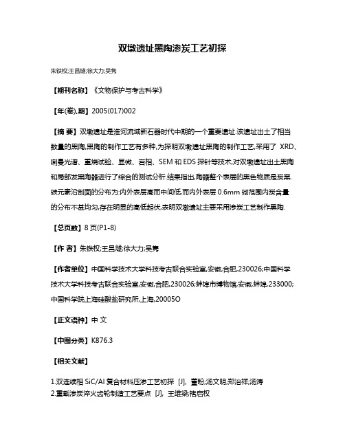
加上 SC泡沫孔对液态合金的约束作用, i 大大减小了合金 内部的对流作用【 。 1 合金 内部对流越小, 合金的补缩能力
越弱 。可见,SC泡沫的综合作用加快了基体合金凝 固, i
增强 了复合材料基体 的连 续性 。 复合材料 的连续 性与复 合压力有密切关系( 如图 3,单一纯铝 的挤压铸 造压力 )
为 3 MP ,单一共 晶铝硅 合金 ( 0 a 含硅量 为 1%~1 %) 1 3 挤压铸造压力约为 7 MP , 0 a 这时复合压力主要作 用是消 除金属熔 体中的气泡和枝 晶臂间 的孔洞【 随着硅含 量 1 。
减 小了合金内部的对流 ,阻碍 了液态合金之间的补缩 , 降 低 了复合材料基体的连续性, 从而大大提高了材料复合所
Si f m / c m p ie C o a  ̄ o ost s
Soi fc tonund e su e l i ai di erprs r JfIr tonofm ol oSi f a n ta i i t AIi C o m en nt
:
2 实
验
泡沫/ I i A 双连续相 复合 材料 ,
挤压铸造所用 的设备 和复合 流程如 图 1 2所示 。 和
・基 金项 目:华 东交 通大 学 博 士启 动 基 金 资助 项 目 ( 10 0 6 0 36 1 ) 收到 稿 件 日期 :2 0.42 0 70 -7 通 讯 作者 :赵 龙 志 作者 简 介 :赵 龙志 ( 97 ) 17 一 ,男 ,江 西 都 昌人 ,博 士 ,副 教授 ,从 事先 进 金 属基 复合 材料 的研 究 。
体 中存在气泡 的可能性减小。与单一铝硅合金相 比,当基
维普资讯
赵龙志 等: i SC泡沫/ 1 连 续相 复 合 材料 连 续 性 的研 究 A双
36 59
域 没有 宏观裂纹 ( 5( ), c ) 图 b ( ) ,只有 少量微观裂纹 ( 5( ) 。增 强体骨架 中的宏观 裂纹严重 地割裂 了 图 d)
浇注温度 :7 0 5 ℃,模具预热温度 :2 0 5 ℃,增强体预热 温度 :80 0 ℃,保压 时间 :4 s 5 。依 次用 2 、1 、7 m 8 5 g 的 SC粉在 玻璃板 上磨制 ,最后 在金相抛光机上用 3 i . 5
和 1m 的金刚石抛 光膏抛光 。材料微观 结构的观察在 g ME 4 F A金相显微镜和 ¥ 6 3 0扫描 电子显微镜下进行 。
图 4为在其它复合工艺参数不变的条件 下, 不同复合 压力制备出复合材料 的形貌 。从图中可以看出,当复合压
力低于 1MP 5 a时,基体铝合金 ( 晶铝硅合金 7 , 9 共 11 ) 0 中均存在不同程度 的缩孔。随着复合压力 的增大 , 缩孔的
数量减少, 缩孔的孔径减小, 当复合压力达到 10 a 5MP 时, 基体中铸造缺陷消失。 其原因是复合压力的增大使基体的 补缩能力增强, 气体在 基体合金 中的溶解度增加 , 以基 所
维普资讯
助
能
材
料
2 7 增刊 (8 卷 0 年 0 3)
合在 YH 23 5 型四柱液压机上 进行,压机的公称压 3 —1A 力 为 35 k 将 SC陶瓷骨架和模 具预热至设定温度 , 10 N。 i
体中不存在孔洞时, 碳化硅泡沫增强铝基复合材料所 需要
材 料复合前先对 SC泡沫进行 预处理 , i 首先用 自来
水对 SC泡沫进行超 声波粗 洗( i 参数设置 :温度 :2 " 5C,
时 间: lmi,功率 :1 0 ,接着 用无 水 乙醇将三 维 O n 0 %) 网络 SC泡沫超声波精洗 1ri,然 后用去离子 水超 声 i 5 n a 波清洗 1 ri,再放入 10 的烘箱 中烘烤 5 ,取出后 0 n a o℃ h 放入干燥 器中备用 。SC泡沫 增强体 与基体铝合金 的复 i
降低 了复合材料的连续性 。
( )随着复合压 力的增加 ,复合材 料的连续性 逐 2
渐增 强。
骨架 的连续性 , 坏 了复合 材料 的整体性 ,大大地 降低 破
了复合材料的连续性 【。SC 泡 沫 内部产 生裂 纹 的根本 8 i 】
具有特有 的拓 扑结构 [,弥补 了非连 续增强体增强 的复 7 】
『 Fce 】 ue. n m t g ar pr e
sc e r pe 帅 t m r-
】
um nu Al i m … g
合材料的不足 , 其增强体通常包括微孔陶瓷和泡沫陶瓷。 微孔陶瓷 的成本较高 [,使 用泡沫 陶瓷作为增强体 能降 8 】 低双连续相复合材料 的制备成 本 ,简化制备工 艺[1。 9 3 -】 双 连续相复合材料 的连续 性包括基体 的连续性 、增强体 的连续 性和界面 的连续性 。材 料的性能和复合材料 的连 续性有密切关系 ,因此研 究 SC A 双 连续相 复合材料 的 i/1 连续性具有重要的理论和实 践意义 。本文研 究 了铸造工 艺 、合金成分和增强体结构对 复合材料连续性 的影响 。
图 3 铝硅合金 s 含量 与挤压铸 造压力 的关系 i
Fi lto f s e z r s u e a d c ntn f S n g 3 Re ai n o qu e e p e s r n o e to i i A lS l y — ial o
的复合压力从 7 MP 提高到 10 a 0 a 5MP 。这主要是 由于 SC i 泡沫 陶瓷增强体的加入加速 了基体合金的凝 固, 阻碍了合 金对 增强体泡沫陶瓷的浸渗。 基体合金 的凝固与合金结晶 的过冷度、凝固速度 以及复合压力的影响机制有关。 铝合
同时基体合金在 功率为 5 W 的坩 锅炉中熔炼 。待合金 k
需要 的压 力。
的增加,铝硅 合金 的结晶温度范 围也慢慢变宽 ,材料所
需要的复合压力也渐渐增大 。
图 4 不 同复合压 力下复 合材料基体 A —i l 合金组 织 s
Co t n fSii a rx w t n e to n m t i/ %
Fi o ph l y ofA ISim arx of c m p ie n e g 4 M r oog — ti o osts u d r
Fi a rc to o e so o p i s g 2 F b a npr c s fc m ost i i e
SC泡沫/ 1 i A 双连 续相复合材 料 由 SC 泡沫陶瓷骨 i 架 增强体和铝基体合 金两部分构 成 。 采用 先驱体泡沫浸 渍 法制备 SC泡沫陶 瓷骨架增 强体 ,体积分数 为 2 %, i 0 泡沫 网孔的尺 寸约为 l mm;基 体材料 为铸造铝 合金 。
体之 间的热膨胀 匹配增 强,复合材料 中残余应力 降低 , 复合材料 的连续性增强 。
关键 词: 双连续性复合材料 ;连续性 ;热残余应 力
中图分类号 : T 3 3 G132 B 3 ;T 1.5 文献标识码 :A 文 章编号 :10 .7 1 0 7增 刊.5 70 0 1 3( 0 ) 9 2 3 6 .3
复合材料 , 究 了 SC泡沫 、复合压 力和合金 成分对复 研 i 合 材料连 续性的影 响。结果表 明 , SC 泡 沫陶瓷的加 i 入 阻碍 了基体合金 流动 ,降低 了复合材料 的连续性 。随
着复合压力 的增加 ,复合材料 的连 续性 逐渐增强 ,当压
力为 10 a ,复合材料 的连续性 最好 。随 着含硅 量 5 MP 时 的增加 , 基体合金 的热膨胀 系数 逐渐 降低 ,基体和 增强
图 1 挤压铸造设备 示意 图
F g 1S h m ai l tai no q e z a tn q i m e i c e tcil r to fs u e ec si g e u p nt us
1 引 言
SC / I i pA 复合材料具有优异 的物理性能和力学性能 , 是应用 于航空航 天和汽 车工 业领 域 的理想材 料[ 1 1 。但 , 2 是,陶瓷增强体 的不连续性和 陶瓷与金属的不润湿性使 陶 瓷颗粒很难均匀地分布在金属基 体 中,增加 了材 料 的 制备成本 , 响了其性能 的提 影 。双连续相复合材料
过程 。合金的形核率越大,金属凝 固的速度也越大。合金 的形核率与液态基体合金 的过冷度有关,SC泡沫的加入 i 没有 改变液态合金的过冷度,即 SC 没有作为 6A 的形 i [1 一 核中心 , SC泡沫 陶瓷增强体没有因为异质形核作用而 则 i 加速 了基体合金的凝固。SC泡沫的加入减少了单位体积 i 内的金属体积 ,从而减少 了单位体积材料 内释放 出的热 量,增加了复合材料 的凝固速度 。SC泡沫独特的三维 网 i 络连通结构,减少 了界面 的面积,增加材料等效导热性, 也使 复合材 料的凝固速度增加。另外,SC泡沫 网络使液 i 态金属合金分割成一个个微小的熔池 , 减轻了复合压力对 液态金属合金的搅拌作用 ,降低 了合金 中气体 的析 出。 再
熔化并达 到浇注温度 时,保温 5 i,然后将 SC 泡沫 mn i 骨架迅速放入模 具中,浇入铝 合金熔液 ,最后合模加压
使合金熔体浸渗入泡沫 骨架 的孔 隙中, 并在 压力下凝 固
成型形成复合材料 ,最 后脱模冷却 。主 要工艺参数为 :
金基 体凝固的过程实质上是液相 中形核和其随后 的长大
d fe e ts u e ep e s r i r n q e z r s u e
32基 体中的含硅量对 复合材料连续性 的影响 .
SC 泡 沫/ 双 连续相 复合材料 中增强体 的连续性 i A1 对 复合材料有重 要的影响 。 在制 备过程 中复合材料经 历 了从 高温到低温过程 , 由于增 强体与基体 的线膨胀 系数 差异 很大 ,在复合材 料 内部产 生很大 的残余应 力[ 】 ¨ , 复杂 的残余应力可 能使 SC增 强体 内部 出现裂 纹, 坏 i 破 复合材料 的连续性 。 图 5( )表 明,SC泡沫增 强纯铝金属基 复合材 料 a i 的增强体 中普遍存在着宏 观裂纹 ,裂纹 的方 向各异 ,而 在 SC 增强铝硅 合金 的复合材料 的增 强体中大部分 区 i