电磁阀说明书D7915-en
电磁阀控制器说明书
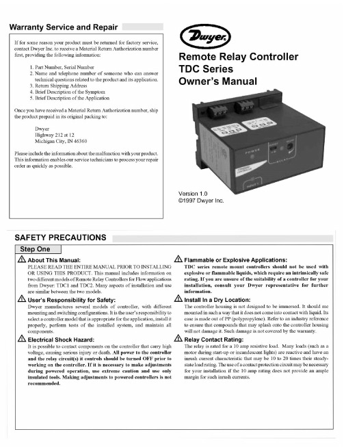
SPECIFICATIONSStep TwoSupply voltage:120 / 240 VAC, 50 - 60 Hz.Consumption:5 Watt Sensor supply:13.5 VDC @ 100 mA Relay type:TDC1:(1) SPDT TDC2:(1) SPDT, (1) Latched SPDT Relay load:250 VAC, 10A, 1/2 hp.Relay mode:Selectable, NO or NC Time delay:0 to 60 seconds LED indication:Sensor, relay & power status Fail safety:Power fail-safe Temperature range:F: -40 to 158 C: -40 to 70 Enclosure rating:Panel or 35 mm DIN Rail (EN 50 022)Enclosure material:Polypropylene (U.L. 94 VO)Certificate number:LR 79326-3 (CSA/NRTL)Dimensions 2.7"1.8"R E L A Y 1R E L A Y 2P O W E R I N V E R T I N V E R T D E L AY D E L AY ONOFF LATCH I N P U T 1I N P U T 2A I N P U T 2B+—+—3.9"3.6"3.1"Make a Fail-Safe System:Design a fail-safe system that accommodates the possibility of relay or power failure. If power is cut off to the controller, it will de-energize the relay. Make sure that the de-energized state of the relay is the safe state in your process. For example, if controller power is lost, a pump will turn off if it is connected to the Normally Open side of the relay.While the internal relay is reliable, over the course of time relay failure is possible in two modes: under a heavy load the contacts may be “welded”or stuck into the energized position, or corrosion may build up on a contact so that it will not complete the circuit when it should. In critical applications, redundant backup systems and alarms must be used in addition to the primary system. Such backup systems should use different sensor technologies where possible.While this manual offers some examples and suggestions to help explain the operation of Dwyer products, such examples are for information only and are not intended as a complete guide to installing any specific system.LR79326 -3Power SupplyRefer to the instructionmanual for installationinstructions.120/240 VAC, 50 - 60 Hz5 Watt250 VAC, 10 A, 1/2 HpMaximum Relay RatingNRTL-C TDC1 Faceplate Approval Label + --+--+--TDC2 FaceplatePower Supply Latch / Invert LogicTime DelayACACGNDSensor Input A*Sensor Input B*Relay ("Relay 2" in LC82)Relay ("Relay 1"in LC82)NCCNOSensor Input 1Latch / Invert Logic Time Delay NCCNO (+)(-)S+ - S + - S Part Number Information:Part #Mat'l Description TDC1PP Flow/No-Flow Controller TDC2PP Dual Flow/No-Flow Controller Functional DiagramINSTALLATION GUIDE TO CONTROLSStep ThreeStep Four Panel DIN Rail Mounting The controller may be mounted by either a back panel using two screws through mounting holes located at the corners of the controller or by snapping the controller on 35 mm DIN Rail.+R E L A Y 1R E L A Y 2PO W E RI N V E R T I N V E R T D E L A Y--+--D E L A Y ONOFF LA T CHI N P U T 1I N P U T 2A I N P U T 2B137254472568669991. Power indicator: This green LED lights when AC power is ON.2. Relay indicator: This red LED will light whenever the controller energizes the relay, in response to the proper condition at the switch input and after the time delay.3. AC Power terminals: Connection of 120 VAC power to the controller. The setting may be changed to 240 VAC if desired. This requires changing internal jumpers; this is covered in the Installation section of the manual. Polarity (neutral and hot) does not matter.4. Relay terminals (NC, C, NO): Connect the device you wish to control (pump, alarm etc.) to these terminals: supply to the COM terminal, and the device to the NO or NC terminal as required. The switched device should be a noninductive load of not more than 10amps; for reactive loads the current must be derated or protection circuits used. When the red LED is ON and the relay is in the energized state, the NO terminal will be closed and the NC terminal will be open.5. Time delay: Use potentiometer to set delay from 0.15 to 60seconds. Delay occurs during switch make and switch break.6. Input indicators: Use these LEDs for indicating Flow or No-Flow status of switch. For NC wiring, an Amber LED indicates No-Flow and no LED indicates Flow. For NO wiring, an Amber LED indicates Flow and no LED indicates No-Flow.7. Invert switch: This switch reverses the logic of the relay control in response to the switch: conditions that used to energize the relay will now de-energize the relay and vice versa.8. Latch switch (TDC): This switch determines how the relay will be energized in response to the two sensor inputs. When LATCH is OFF, the relay responds to switch Input 2A only; when LATCH is ON,the relay will energize or de-energize only when both switches (2A and 2B) are in the same condition (Flow or No-Flow). The relay will remain latched until both switches change conditions.9. Input terminals: Connect the switch wires to these terminals:Note the polarity: (+) is a 24 VDC, 50 mA power supply (connected to the red wire of a Dwyer flow switch), and (-) is the common ground path from the switch (connected to the black wire). Also, the (S) is a 14VDC, 25 mA supply (connected to the white wire). If polarity between the red and black wires is reversed, the switch will change from NC to NO. 3.475" 2.2".275".225"35 m m D I N R a i l Note: Always install the controller in a location where it does not come into contact with liquid.Connecting switches to input terminals:Please note a difference between Dwyer flow switches (N-channel and P-channel). Use only the N-Channel switches with the TDC series of controller. Wire the Red wire to the (+) terminal and the Black wire to the (-) terminal. Wire the White wire to the (S). See the illustration below to indicate wiring for your switch. Reversing Red and Black wire will change switch from NC to NO. Note: connect the Shield wir e on the Flow switch to the GND terminal if required.LED Indication Use LED's located above the input terminals to indicate whether the switch is in a Flow or No-Flow state. With the flow switch wired NC, the Amber LED indicates No-Flow and no LED indicates flow. Wiring the switch NO (reversing the Red and Black wires), the Amber LED indicates Flow and no LED indicates No-Flow.NO Wiring Amber NO Wiring OFFINPUT1I N P U T 2A I N P U T 2B W h i t e B l a c k FT10-XX02GT10-XX02NC Wiring FT10-XX02GT10-XX02NO Wiring O N O F F L A T C H R e d W h i t e R e d B l a c k INPUT 14 VDC 25 mA Max.( - )( S )GND 24 VDC 50 mA Max.( + )NC Wiring Amber NC Wiring OffINSTALLATIONTROUBLESHOOTING Step FiveStep Six VAC Power Input WiringNote: Polarity does not matter with the AC input terminalController Logic For all controllers, please use the following guide to understand the operation of the Dwyer TDC1/TDC2 controllers.1.Make sure the Green power LED is On when power is supplied to the controller.2.For NC switch wiring, the input LED's on the controllers will be Amber when the switch reads No-Flow and Off when the switch reads Flow.3.The input LED will always respond to its corresponding relay LED.With invert Off, the relay LED will be On when the input LED is On and Off when the input LED is Off. With invert On, the relay LED will be Off when the input LED is On and On when the input LED is Off.4.The relay may be wired either NO or NC. The normal state of the relay is when its LED is Off. With the LED On, the relay is in the energized mode and all terminal connections are reversed.5.TDC model only, Latch ON operation: When both input LED's are ON, the relay will be energized (red LED On). After that, if one switch input turns Off, the relay will remain energized. Only when both switch LED's are Off will the controller de-energize the relay.The relay will not energize again until both switch LED's are ON.Reversing Invert switch will reverse logic. See the Logic Chart below for further explanation.Relay Input WiringThe controllers use dry contact Single Pole DoubleThrow (SPDT) relays rated at 250 Volts AC, 10Amps, 1/2 Hp. The terminals are labeled NormallyOpen (NO), Common and Normally Closed (NC).Below shows four examples of basic wiring:Ground Neutral Hot + --Ground Neutral Hot+--POWER120 VAC, 50 - 60 Hz AC 240 VAC, 50 - 60 Hz AC GNDAlarm Contact @ No-Flow Pump Open @ No-FlowNO NCRELAY OUTPUT 250 VAC, 12 A, 1/2 Hp C + --+ --+--+ --Note: The invert is switched between the Alarm and Pump Wirings.Normally Open Relay Wiring Normally Closed Relay Wiring + --+ --+--+ --Note: The inver t is switched changes between Nor mally Open and Normally Closed.Changing from 120 to 240 VACRemove the back panel of the controller and gently slide the printed circuit board from the housing. Use caution when removing the PCB.Located jumpers JWA, JWB and JWC on the PCB. To change to 240VAC, remove jumpers from JWB and JWC and place a single jumper across JWA. To change to 120 VAC, remove jumper JWA and place jumpers across JWB and JWC.J W B JW C J WA J W B JWC J WA120 VAC 240 VACInvert Off Input A ON OFF InputB No Effect No Effect Relay ON OFF Invert ON Input A ON OFF InputB No Effect No Effect Relay Off On Invert Off Input A ON OFF ON OFF InputB ON ON OFF OFF Relay ON No Change No Change OFF Invert ON Relay Off No Change No Change On Input A ON OFF ON OFF InputB ON ON OFF OFF — +Latch Off On Off — +On Off Latch Off — +On Off — +On Off Latch ON Latch ON Relay Latch Logic Chart。
高流直挂NAMUR阀门电磁阀系列产品简介说明书
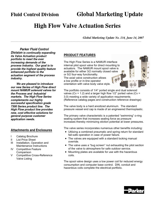
Fluid Control Division Global Marketing Update High Flow Valve Actuation SeriesGlobal Marketing Update No. 134, June 14, 2007 __________________________________________________________________________________________________________________________________ Parker Fluid ControlDivision is continually expanding its Valve Actuation product portfolio to meet the ever increasing demands of the process industry. Our goal is to provide the highest quality feature enhanced portfolio to the actuation segment of the process industry.We are pleased to introduce our new Series of High Flow direct mount NAMUR solenoid valves for the Process and Industrial markets. The High Flow Series complements our highly successful specification grade 7300 Series product line. The High Flow product line provides new, cost effective solutions for general purpose customer application needs.Attachments and EnclosuresI Catalog BrochureII List Price SheetIII Installation, Operation andMaintenanceInstructionsIV Competitive FeatureComparisonV CompetitiveCross-Reference ValveListing PRODUCT FEATURESThe High Flow Series is a NAMUR interfaceinternal pilot spool valve for direct mounting toactuators. The NAMUR mount spool valve isavailable for either 3/2 normally closed valveor 5/2 four-way functionality.The axial valve construction allowsa low profile or in-line operatororientation with valve body valve style.The portfolio consists of 1/4” ported single and dual solenoid valves (Cv = 1.2) and a larger high flow 1/2” ported valve (Cv = 3.0) meeting a wide variety of application requirements. (Reference catalog pages and construction reference drawings)The valve body is a hard anodized aluminum. The standard pressure vessel end cap is made of an engineered thermoplastic.The primary valve characteristic is a patented “swimming” o-ring sealing system that increases sealing force as pressure increases thereby minimizing stiction potential at lower pressures. The valve series incorporates numerous other benefits including: •Utilizing a combined pneumatic and spring return for standard fail-safe operation in case of power failure.•The valves are equipped with a standard locking manual override.•The valve uses a “bug screen” nut exhausting the pilot section of the valve to atmosphere for safe outdoor service.•Mounting plates are available for use with the hazardous coils.The spool valve design uses a low power coil for reduced energy consumption and computer base control. DIN, conduit and hazardous coils complete the electrical portfolio.Global Marketing Update No. 134, June 14, 2007 __________________________________________________________________________________________________________________________________ OPERATION FUNCTIONALITY3/2 Single Solenoid (4 ported, 2 position)NAMUR valve, solenoid operated, for 3-way normally closed operation. In case of an electrical or air failure, valve returns to a fail-safe position through pneumatic and assisted spring return.5/2 Single Solenoid (5 ported, 2 position)NAMUR valve solenoid operated, for 4-way, 2 position operation. In case of an electrical or air failure, valve returns to a fail-safe position through pneumatic and assisted spring return.5/2 Dual Solenoid (5 ported, 2 position)NAMUR valve used for 4-way, 2-position operation. In case of an electrical or air failure, valve “fails as is”. Therefore, valve remains in last position upon failure and will not return to a predetermined position.5/3 Dual Solenoid, Center Position Closed (5 ported, 2 position)NAMUR valve used for 4-way, 2-position operation. In case of an electrical or air failure, the spool returns to the center position thereby removing pressure to the cylinder ports.TECHNICAL PRODUCT CHARACTERISTICSThe new line of valve actuation products offer many features and benefits as follows:Modular construction – Facilitates use of various body configurations and coil options.Mounting Configurations - Direct mount NAMUR pattern with axial operator orientation for single and dual solenoid models for low profile mounting requirements.Manual Override – Standard on all models for manual valve operation during start-up and diagnostic procedures.7mm (1.2Cv ) and 12mm (3.0 Cv) orifice sizes – Multiple sizes to meet various application demands to ensure the solenoid valve is properly sized.Body Materials - Lightweight anodized aluminum.Spool Design – Stainless steel with NBR sealing materials.Exhaust Pilot Cap– Protected pilot sleeve exhaust using “Bug Screen” nut. Helps protect against plugging, dirt, and insects, etc.Ratings – Meets pressures up to 150 psi.Ambient Temperatures – From 14°F (-10°C) to 122°F (50°C), serving most temperature environments. Fluid Temperatures – From 32°F (0°C) to 104°F (40°C).COIL PRODUCT CHARACTERISTICSA selection of low power encapsulated coils as follows:•DIN coil - with 3-pin DIN 43650 type B plug.•Conduit - 3-wire coil.•Hazardous – 3-wire coil with FM and CSA agency approvals meeting Class 1, Groups A,B,C,D and Class II, Groups E,F,G. Meets EEx m II T4 Division 1 requirements.NAMUR INTERFACEMany actuator manufacturers utilize a common mounting pattern referred to as a NAMUR interface for mounting configurations of solenoid valves.The actuator interface dimensions for NAMUR mounting of the pilot valve to the actuator is shown below (dimensions in millimeters).MATERIALS OF CONSTRUCTIONBody: Anodized AluminumEnd Covers: Thermoplastic – Glass-Filled Polyamid 6/6Plunger: 430 Stainless SteelCore Tube: 304 Stainless SteelSteelSprings: StainlessSeals: NBRCages: Polyamide Filled ThermoplasticSteelSpool: StainlessShading Rings: CopperMOUNTING BOLTSThe standard NAMUR interface includes (2) mounting bolts to mount the valve on to the actuator, a positioning stud and two O-rings seals.MOUNTING PLATESDue to the increased width of the hazardous coil to comply with FM and CSA certifications, a mounting plate must be installed as shown in the photograph.The mounting plate kit contains the plate, 2 o-rings, and 2 longer mounting screws.For the ¼” port valve, order kit N60001. For the ½ “ port valve, order kit N60002.ElectricalStandard voltages and voltage code:VOLTAGE CODE 12VDC A 24VDC B 120/60 C 240/60 D 24/60 E 120/50-60 F 240/50-60 GSolenoid Coil SpecificationsThe electrical portfolio is comprised of general purpose class F DIN coil per 43650B and conduit class H coils rated for NEMA classification Types, 1, 2, 3, 3S, 4, 4X. In addition, the hazardous location class H coil is rated for NEMA classification Types 7 and 9; Class I, Divisions 1 and 2, Groups A,B,C,D and Class II, Division 1, Groups E,F,G. The coils are rated for continuous duty application demands.The electrical selector table summarizes each coil specification:Coil Type Coil Part Number Class Protection Construction Agency22mm DINND1x F DIN connector needed for IP65 protection Per DIN 43650B epoxy moldedUL,CSA Conduit –Ordinary locationNC1x H Type 1,2,3,3S,4,4X Epoxy molded, ½ inch NPT conduit None Conduit –Hazardous locationNH1xHType 4X,7,9½ inch NPT conduitCSA,FMCOMPETITIVE FEATURES AND BENEFITSThe primary valve characteristic is a patented “swimming” o-ring sealing system that increases sealing force as pressure increases thereby minimizing stiction potential at lower pressures.The diagram shows a typical cross section view of the valve.valve-head to keep moisture out in brass or in stainless steel available on request, only in combination with alu-head Spool in stainless steel, other inner-parts made from brass, NBR, POM stainless steel Fiber-enforced PA-head, aluminium-version on request 360° turnable,Date CodePRODUCT LABELINGValves are sold in either:• A modular format ordering pressure vessel and coil separately. • Fully assembled with coil assembled to pressure vessel.In either case, the pressure vessel valve body provides the valve identification information defining the valve part number, performance rating and date code. Sample pressure vessel markingCoils will be marked with the appropriate part number, voltage and wattage, and agency information.Sample coil markingAll valves will be packaged with an installation, operation and maintenance instruction sheet indicating conformity with the CE Mark.ORDERING INFORMATIONPRODUCT OFFERINGReference the enclosed catalog brochure (Attachment I) describing the High Flow Series product offering. The catalog pages describe the valve features, general specifications, valve and electrical selection guide, dimensional drawings, and ordering information.PRICINGPressure Vessel list prices for the High Flow NAMUR Series valves are shown in Attachment II. ORDERING INFORMATIONThe Series uses a simple valve number to identify each model. The valves are available fully assembled or in modular form allowing application flexibility in electrical selection. The electrical parts can also be purchased in modular form.Reference the enclosed catalog pages.•When purchasing individual pressure vessels, select the pressure vessel shown on the catalog page and associated list price.•When ordering electrical parts, select the electrical part and associated list price for standard voltages.•When ordering complete valves, add the list price of each component to determine the complete list price for the fully assemble valve selected.The voltage code is the last character of the fully assembled valve or electrical part selected. For example, selecting a single solenoid, 5/2 configuration, 120/60 DIN coil, the complete valve number is:U341N03 + ND1FAVAILABILITY AND DELIVERYParker Fluid Control Division plans to maintain an appropriate service level of finished goods stock to meet business demand of the following NAMUR mount valves. If finished goods stock is available, units will be shipped within 5 business days from receipt of order for order quantities of 25 units or fewer:Product Class 1 Items:U331N03U341N03ND1B, ND1F, ND1G - 24vdc, 120vac, 240vacNC1B, NC1F, NC1G - 24vdc, 120vac, 240vacNH1B, NH1F, NH1G - 24vdc, 120vac, 240vacProduct Class 4 Items - the estimated lead-time (subject to change) is 4 weeks from receipt of order.U347N03U342N03U331N04U341N04ND1A - 12vdcNC1A - 12vdcNH1A - 12vdcAs always, for larger customer orders requiring shorter lead-times, Parker Fluid Control Division will work jointly with each customer by establishing finished goods items to meet customer provided forecasts.DISCOUNTSParker Fluid Control Division’s standard published discounts apply. Current terms and conditions apply for the product.SERVICERETURNSParker Fluid Control Division’s standard return policy applies.REPAIR PARTSParker Fluid Control Division is NOT offering component repair kits for field service at this time. Since the valve is a small, cost effective product, industry experience shows the process markets will replace the complete valve rather than rebuild the valve in the field.INSTALLATION OPERATION AND MAINTENANCE (IOM)An IOM has been created describing valve operation, installation and mounting instructions, maintenance, and troubleshooting procedures for the high flow Series NAMUR valves. Reference Attachment III, IOM HN01.WARRANTYParker Skinner’s standard 2 year warranty policy applies to the pressure vessel, coil and enclosures.PROMOTIONPromotional materials have been prepared to expedite introduction into the market place.CATALOG / LITERATURE• A new catalog has been created containing the features, specifications and outline drawings of the high flow Series valves.• A product launch announcement containing product introduction materials and detailed competitor information will be distributed to each Territory Sales Manager.TRAINING•Each Territory Sales Manager should contact their respective Fluid Control Division Authorized Distributor and Valve Actuation Accounts to arrange training.•The new high flow Series valves will be included in Fluid Control Division’s Valve Actuation Training Program.•Samples of the new high flow Series actuation valves will be provided upon receipt with a complete sample request form following standard Skinner Valve ™ sample procedures.PHASE-OUT OF 2340, 3300 and 7341 Series Product LinesThe introduction of the new product line has resulted in significant product overlap with the 2340, 3300 and 7341 series valves. Therefore, we are taking the following actions to phase out these product lines. Due to the low volume of many of the products, the old families will be replaced by the new High Flow NAMUR valve as follows:The Phase In – Phase Out schedule will begin upon introduction of the new High Flow NAMUR valve. It may be possible to order a specific older model until current inventory is fully depleted at which time the old product will no longer be available. Parker reserves the right to discontinue the old products sooner if conditions warrant.COMPETITIVE REVIEWReference Competitive Feature Comparison of select valves in Attachment IV. The attachment contains a broad selection of valves representative of the competitive offering.Attachment V provides a competitive cross-reference part number listing based on available information for the individual competitors.ASCO is considered the market leader for actuation valves. Other primary competitors include Versa, Automatic, and Herion.Below is a general description of the competitive product offerings.ASCOThe ASCO 8551 Series offers a product line of NAMUR and pipe mount versions. The portfolio consists of pad mount valves with various operator configurations with single and dual solenoids.In general, the ASCO 8551 Series consists of:•Anodized aluminum and stainless steel body using resilient spool construction. •Convertible 3-way and 4-way models based on the newer version. The older version consists of non-convertible 3-way and 4-way models that are similar to the 7300 Series. •20/35 to 150 psi operating pressure differential.•Single and dual solenoid, vertical and axial operator models available.•Cv 0.50 to 0.86.•AC versions from 2.5 watts to 10.1 watts.DC versions from 3.0 watts to 11.6 watts.•DIN, watertight and explosion solenoids available based on model.The Parker High Flow Series NAMUR mount valves are specified to meet the application requirement. A conversion or mounting plate is not required when using a DIN coil. The valve mounts directly to the actuator in a very cost-effective and efficient manner.VersaVersa offers a series of valves for process control markets including applications for pneumatic actuators and 316 stainless valves for corrosive requirements. The valve offering consists of NAMUR, body ported, lockout valves, latching and manual reset valves and redundant solenoid valves.Specific to the actuation area, Versa offers a convertible 3-way / 4-way version and direct acting 3-way pad mount valve. Available options include Intrinsically Safe, Low power and CENELEC flameproof enclosures.•3/2, 5/2 port plug versions. Valves field convertible by relocating a port plug converting from 3-way to 4-way or 4-way to 3-way.•Anodized aluminum, stainless steel and brass body using resilient spool construction. •Single and dual solenoid models (5/2) and dual solenoid centered position (5/3) with standard manual override.•15 to 115 psi operating pressure, Cv 0.75.•DIN, conduit and explosion solenoids available based on model.•8.5 watt AC, 10.5 watt DC.•Class A or F insulation.Automatic Valve Co. (AVC)They are considered the low price player in the market. They offer a NAMUR mount COMPACT Series. The series has limited options, but offers the ability to order valves with the solenoid on the left or right side.•3/2, 5/2 port plug versions, 1/4” npt porting only.•Anodized aluminum body using resilient spool construction.•40 to 150 psi operating pressure differential, Cv 1.0.•NEMA 4 and 7 solenoids, remote air and manual operators.•DIN, conduit and explosion solenoids available based on model, coil ratings to Class H. Herion•3/2, 5/2 port plug versions, NAMUR mount, 1/8” NPT, ¼” NPT, ½” NPT.•Anodized aluminum body using resilient spool construction.•25 to 150 psi operating pressure differential, Cv 1.1 to 1.4.•NEMA 4 and 7 solenoids, manual operators.•Low power coils available at reduced ratings.•DIN, conduit and explosion solenoids available based on models.•Locking and momentary manual override available.•Requires spacer plate for hazardous coil.Max-Air TechnologyU.S. division of M Technology Srl located in Italy. Also offer rack & pinion actuators and position indicators and mechanical switches that can be assembled as a complete unit.•3/2, 5/2 port plug versions, 1/4” npt porting only.•Epoxy coated aluminum body with plated spool. And standard manual override.•DIN and explosion solenoids available based on model, Class F standard, Class H optional. •Uses a pop-up air indicator located in pilot section to indicate if the solenoid valve is pressurized.•Optional IS and ATEX DIN coil construction.Q&A SESSIONQ? Why did we introduce the High Flow NAMUR Series valve product line?The principle reason for introducing the valve line is to meet increasing market demands for smaller, cost effective valve models for the process valve actuation markets. The Parker 7300 Series valve line offers a high-end specification grade product in multiple bodymaterials to meet general purpose ordinary requirements to the most stringent application requirements. Also, the 2340 series of aluminum body valves lacked a suitable hazardous coil limiting application potentials.The new product line overcomes the 2340 series deficiencies at a most competitive price for general purpose application requirements. The portfolio includes expanded models with higher flow factors for larger actuator designs. The new line includes a 1/2” namur valve to accommodate the trend toward larger actuators and higher flows.Finally, we’re continuing our strategic thrust in the process markets with a new product offering and responding to competitive product positions.Q? Will the High Flow Series product line replace the 2340 Series and 3300 Series valves?In a word, yes. First, since the introduction of the 2340 series and 3300 series valves(dating back to the late ‘90’s), many changes have taken place in the market. The general purpose ordinary location market generally does not require the high technical or safety standards found in these product lines. Due to deficiencies in the former product lines, specifically the lack of a hazardous coil, we were not able to meet the availability and price competitiveness. The current product lines are focused toward higher technicalrequirements resulting in low-volume market segments and overlap price-wise with the 7300 Series valve lines. To reduce complexity and offer a simplified, cost-effective processactuation valve line, the 2340 catalog portfolio will (eventually) be phased-out.Q? Describe the comparison to the 7300 product line.The High Flow Series offers similar product features and benefits compared to the 7300 Series, in particular:• Total modularity.•Interchangeable electrical parts.•Unique spool designs to eliminate risk of sticking.•High quality in proven valve designs.•Standard manual override.The distinctive features of the High Flow Series compared to the 7300 Series include:• Smaller physical size.•More cost effective compared to 7300 with manual override (for certain type application needs).Q? Where must the 7300 series valves be used versus the new line?The 7300 series contains features, multiple operator configurations and electrical coilsappropriate for more demanding critical applications including:•Higher flows appropriate for higher actuator torque specifications.•Intrinsically Safe (IS) and ultra low power environmental conditions.•Manual reset options used as a safety device on solenoid valves to prevent process resumption without manually resetting each valve.•Low temperatures application demands of –40°F/C.•Field convertible manual overrides including locking and momentary requirements. Q? Will a conversion plate eventually become available?The product line contains individual 3-way and 4-way valve configuration. When utilizing a DIN coil, this method provides the most cost-effective, competitive solution. Granted, whilea conversion plate offers the benefit of using one style valve, it also adds significant andunnecessary costs. Since the valve is focused and priced to pursue higher volumerequirements, the valve functionality will be known.。
卡莫兹系列3电磁阀手册2022-11-08说明书
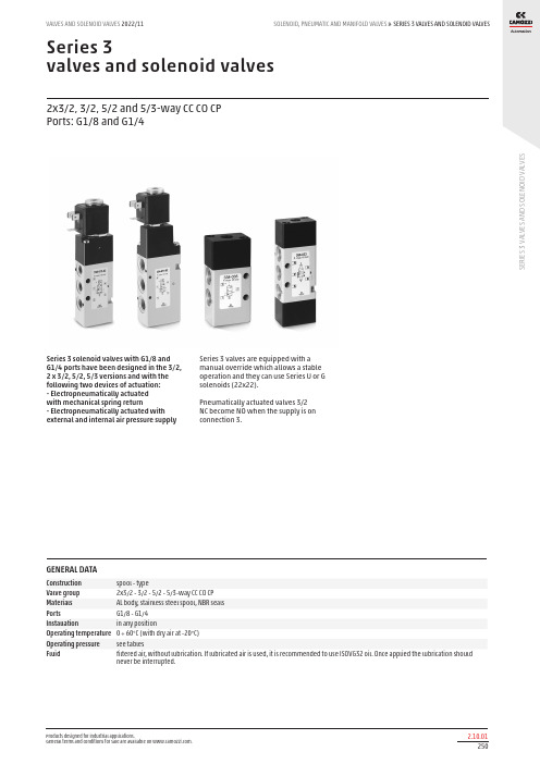
SERIES 3 VALVES AND SOLENOID VALVESVALVES AND SOLENOID VALVES 2022/11SOLENOID, PNEUMATIC AND MANIFOLD VALVES S E R I E S 3 V A L V E S A N D S O L E N O I D V A L V E S>Series 3valves and solenoid valves2x3/2, 3/2, 5/2 and 5/3-way CC CO CP Ports: G1/8 and G1/4Series 3 solenoid valves with G1/8 and G1/4 ports have been designed in the 3/2, 2 x 3/2, 5/2, 5/3 versions and with thefollowing two devices of actuation: - Electropneumatically actuated with mechanical spring return- Electropneumatically actuated with external and internal air pressure supplySeries 3 valves are equipped with a manual override which allows a stable operation and they can use Series U or G solenoids (22x22).Pneumatically actuated valves 3/2 NC become NO when the supply is on connection 3.GENERAL DATAConstruction spool - typeValve group 2x3/2 - 3/2 - 5/2 - 5/3-way CC CO CP Materials AL body, stainless steel spool, NBR seals Ports G1/8 - G1/4Installation in any position Operating temperature 0 ÷ 60°C (with dry air at -20°C)Operating pressure see tablesFluidfiltered air, without lubrication. If lubricated air is used, it is recommended to use ISOVG32 oil. Once applied the lubrication should never be interrupted.SERIES 3 VALVES AND SOLENOID VALVES SOLENOID, PNEUMATIC AND MANIFOLD VALVES >VALVES AND SOLENOID VALVES 2022/11S E R I E S 3 V A L V E S A N D S O L E N O I D V A L V E SCODING EXAMPLETYPES OF MANUAL OVERRIDEExample of solenoid valve with a bistable standard manual Example of solenoid monostable valve (IM) and bistable valveSERIES 3 VALVES AND SOLENOID VALVESVALVES AND SOLENOID VALVES 2022/11SOLENOID, PNEUMATIC AND MANIFOLD VALVES S E R I E S 3 V A L V E S A N D S O L E N O I D V A L V E S>3/2-way solenoid valve, G1/8, monostable - Mod. 338..., Mod 348...These solenoid valves, which have electropneumatic actuation and spring return, are available in the NC (closed) or NO (open) version.*Side fixing holes not present3/2-way solenoid valve, G1/8, bistable - Mod. 338...These solenoid valves, which have electropneumatic actuation and return, assume the NC (closed) or NO (open) position depending onthe last pulse received.SERIES 3 VALVES AND SOLENOID VALVES SOLENOID, PNEUMATIC AND MANIFOLD VALVES >VALVES AND SOLENOID VALVES 2022/11S E R I E S 3 V A L V E S A N D S O L E N O I D V A L V ES2 x 3/2-way solenoid valve, G1/8 - Mod. 338D..., 348D... e 398D...These solenoid valves are available in versions with 2 x 3/2 valves in the same valve.5/2-way solenoid valve, G1/8, monostable - Mod. 358...These solenoid valves with electropneumatic actuation and mechanical or pneumatic spring return are suitablefor controlling double-acting cylinders.S E R I E S 3 V A L V E S A N D S O L E N O I D V A L V ES5/2-way solenoid valve, G1/8, bistable - Mod. 358...These solenoid valves with electropneumatic actuation and return are suitable for controlling double-actingcylinders.5/3-way solenoid valve, G1/8, - Mod. 368... Mod. 378... Mod. 388...CC = Centres Closed CO = Centres Open CP = Pressure CentresS E R I E S 3 V A L V E S A N D S O L E N O I D V A L V E S3/2-way solenoid valve, G1/4, monostable - Mod. 334... Mod 344...These solenoid valves, which have electropneumatic actuation and spring return,are available in the NC (closed) or NO (open) version.3/2-way solenoid valve, G1/4, bistable - Mod. 334...These solenoid valves, which have electropneumatic actuation and return assume the NC (closed) or NO (open)position depending on ther last pulse received.S E R I E S 3 V A L V E S A N D S O L E N O I D V A L V E S2 x 3/2-way solenoid valve, G1/4 Mod. 334D... 344D... and 394D...These solenoid valves are available in versions with 2 x 3/2 valves in the same valve.5/2-way solenoid valve, G1/4, monostable - Mod. 354...These solenoid valves, which have electropneumatic actuation and spring return, are suitable for operatingdouble-acting cylinders.SERIES 3 VALVES AND SOLENOID VALVES SOLENOID, PNEUMATIC AND MANIFOLD VALVES >VALVES AND SOLENOID VALVES 2022/11S E R I E S 3 V A L V E S A N D S O L E N O I D V A L V ES5/2-way solenoid valve, G1/4, bistable - Mod. 354...These solenoid valves, which have electropneumatic actuation and spring return, are suitable for operatingdouble-acting cylinders.5/3-way solenoid valve, G1/4, - Mod. 364... Mod. 374... Mod. 384...CC = Centres Closed CO = Centres Open CP = Pressure CentresSERIES 3 VALVES AND SOLENOID VALVESVALVES AND SOLENOID VALVES 2022/11SOLENOID, PNEUMATIC AND MANIFOLD VALVES S E R I E S 3 V A L V E S A N D S O L E N O I D V A L V E S>3/2-way valve, G1/8 or G1/4, monostable3/2-way valve, G1/8 or G1/4, bistableSERIES 3 VALVES AND SOLENOID VALVES SOLENOID, PNEUMATIC AND MANIFOLD VALVES >VALVES AND SOLENOID VALVES 2022/11S E R I E S 3 V A L V E S A N D S O L E N O I D V A L V ES5/2-way valve, G1/8 or G1/4, monostableIn-line or manifold mounting5/2-way valve, G1/8 or G1/4, bistableIn-line or manifold mountingS E R I E S 3 V A L V E S A N D S O L E N O I D V A L V E S5/3-way valve, G1/8 or G1/4In-line or manifold mounting2 x 3/2-way valve, G1/8 or G1/4In-line or manifold mountingS E R I E S 3 V A L V E S A N D S O L E N O I D V A L V ESManifold bars with separate exhausts (low version)The following is supplied: 2x feet1x manifold 1x inlet fitting 1x plug 4x washersManifold bars with separate exhausts (high version)The following is supplied: 2x feet1x manifold 1x inlet fitting 1x plug 4x washersS E R I E S 3 V A L V E S A N D S O L E N O I D V A L V E SThe following is supplied:3x interface O-Rings manifold/manifold; 2x fixing nuts; 2x junction plugs;9x interface seals valve/manifold (CNVL-3H3) or 3x interface seals valve/manif. (CNVL-4H3);6x fixing screws for valvesCNVL-3H3: for Series 3, G1/8 CNVL-4H3: for Series 3, G1/4Initial / final Module with 2 positions - Mod. CNVL-...Initial module with 2 positions The following is supplied:3x interface O-Rings manifold/manifold; 2x fixing nuts; 2x junction plugs;6x interface seals valve/manifold (CNVL-3H2) or 2x interface seals valve/manif. (CNVL-4H2);4x fixing screws for valvesCNVL-3H2: for Series 3, G1/8 CNVL-4H2: for Series 3, G1/4Intermediate module with 3 positions - Mod. CNVL-...The following is supplied:3x interface O-Rings manifold/manifold;2x fixing nuts; 2x junction plugs;9x interface seals valve/manifold (CNVL-3I3) or 3x interface seals valve/manif. (CNVL-4I3);6x fixing screws for valvesCNVL-3I3: for Series 3, G1/8 CNVL-4I3: for Series 3, G1/4S E R I E S 3 V A L V E S A N D S O L E N O I D V A L V ESThe following is supplied:3x interface O-Rings manifold/manifold; 2x fixing nuts; 2x junction plugs;6x interface seals valve/manifold (CNVL-3I2) or 2x interface seals valve/manif. (CNVL-4I2);4x fixing screws for valvesCNVL-3I2: for Series 3, G1/8CNVL-4I2: for Series 3, G1/4Intermediate module with 1 position - Mod. CNVL-...The following is supplied:3x interface O-Rings manifold/manifold; 2x fixing nuts; 2x junction plugs;3x interface seals valve/manifold (CNVL-3I1) or 1x interface seal valve/manif. (CNVL-4I1);2x fixing screws for valvesCNVL-3I1: for Series 3, G1/8CNVL-4I1: for Series 3, G1/4Terminal module Mod. CNVL-*HThe following is supplied:2x fixing nutsCNVL-3H: for Series 3, G1/8CNVL-4H: for Series 3, G1/4Interface module manifold between Series 3 G1/8 and G1/4The following is supplied: 3x interface seal 2x screws 2x pins 4x plugs6x O-RingsS E R I E S 3 V A L V E S A N D S O L E N O I D V A L V E SIntermediate plate for additional inlet and exhaust pressureThe following is supplied: 3x O-Rings2x fixing screwsCNVL-3P: for Series 3, G1/8CNVL-4P: for Series 3, G1/4Separation diaphragmFor separation of channel: 1 - 3 - 5.The following is supplied:1x diaphragmBlanking plug Mod. TCNVL for manifoldsThe following is supplied:1x blanking plug1x O-RingBlanking plate Mod. CNVL for manifoldsIt is used to blank vacant positions of a manifold.The following is supplied: 2x fixing screws 3x O-Rings。
电磁阀说明书

电磁阀说明书电磁阀说明书1. 简介电磁阀是一种常见的控制装置,通过电磁力作用来控制介质(例如液体、气体或气体)的流动。
电磁阀广泛应用于各种工业领域,例如液压系统、气动系统、冷却系统等。
本说明书旨在介绍电磁阀的工作原理、结构、安装和使用方法。
2. 工作原理电磁阀是由电磁线圈和阀体组成的。
电磁线圈通过通电产生磁场,使阀体内的阀芯移动,从而开启或关闭阀门。
在通电或断电状态下,电磁阀起到控制介质流动的作用。
当线圈通电时,磁场吸引阀芯,使阀门打开;当线圈断电时,阀芯弹簧恢复原位,阀门关闭。
3. 结构电磁阀主要由以下几个部分组成:- 阀体:包含阀门和管道接口,用于控制介质的流动。
- 阀芯:位于阀体内,受到电磁力控制,用于打开或关闭阀门。
- 电磁线圈:位于阀体外侧,通过通电产生磁场,控制阀芯的移动。
- 弹簧:用于恢复阀芯原位,关闭阀门。
- 密封件:防止介质泄漏,保证阀门的密封性能。
4. 安装方法在安装电磁阀时,需要注意以下几点:1. 选择合适的阀门类型和规格,根据实际需要确定。
2. 确保安装位置符合要求,避免电磁阀受到外力干扰或介质堵塞。
3. 注意阀门的进出口方向,确保介质能够顺利流动。
4. 连接接口要牢固可靠,确保不会发生泄漏。
5. 注意接线的正确性,防止电磁阀工作异常。
5. 使用方法电磁阀使用时需要注意以下几点:1. 确保电源的正常供应,电压和频率要与电磁阀的标定值相匹配。
2. 操作开关或控制装置,控制电磁阀的通电和断电。
3. 注意使用环境温度,避免过高或过低的温度对电磁阀的影响。
4. 定期检查电磁阀的工作状态,确保正常运行。
5. 当电磁阀长时间不使用时,应断开电源,并进行必要的维护。
6. 注意事项在使用电磁阀时,需要特别注意以下事项:1. 严禁在电磁阀上进行改装或修理,以免造成故障或危险。
2. 禁止超负荷使用电磁阀,确保电磁阀在额定压力和温度下正常工作。
3. 当电磁阀出现异常情况(如漏电、发热等)时,应立即停止使用,并寻求专业人士的帮助。
电磁阀维修使用说明
电磁阀安装指南电磁阀是控制(管理)系统的执行器。
其作用是根据控制设备发出的电信号,开启和关闭管路中的水流。
电磁阀为常闭式,即在不通电的情况下,阀关闭;通电后,阀开启。
美林地景电磁阀共10个系列,100多个规格型号,通径20~500mm,工作压力0.03~1.5MPa。
所有电磁阀均可用于常温清水,一部分电磁阀可用于河水、湖水等非洁净水。
MPV100、MPV150、MPV200、MPV300、21024-10-E、21024-15、21024-20是最常用的八种型号。
1.安装电磁阀前, 应先清除管道内的异物,并对管路进行彻底冲洗。
2.为检修方便,应在电磁阀上游加装一个手动阀门。
3.田间(室外)使用时,电磁阀应安装于阀门井里。
阀门井的直径一般不应小于800mm。
电磁阀应高出井底一段距离,建议不小于200mm。
4.阀的进、出水口不得装反,阀体上的箭头表示水流方向。
5.阀的进、出水口为标准内螺纹,与阀连接的接头或管道应为同尺寸的外螺纹。
在外螺纹上缠两圈聚四氟乙烯带(俗称生料带),先用手把螺纹拧紧,再用扳手拧1-2圈。
不要把接头拧得太紧,以免挤压先导孔出口,使阀不能正常工作。
6.电磁阀与控制装置之间的连线的截面尺寸应足够大,以免因回路的电压降太大,造成阀不能正常工作。
建议采用控制电缆,其规格型号的选择同常规电器。
7.室外导线与导线之间的连接应采用防水接头。
8.电缆的铺设应遵循常规电器的有关规定。
必要时,电缆应加套管。
一、电磁阀工作原理目前常用电磁阀多为隔膜阀,其工作原理是:阀体分为上下两个室,中间为隔膜,在水压相同的条件下,由于隔膜上下受力面积不同而产生压力差,达到切断水流的目的。
电磁阀开启状态:当通过远程控制器给电信号或手动旋转电磁头,排水通道打开,上隔膜室内水排出,室内压强减小,作用在上隔膜的压力变小,在上游压力作用下推动隔膜向上运动,打开管路通道。
电磁阀关闭状态:手动关闭或断开电磁头电信号,使排水通道关闭,上隔膜室内慢慢充满水,等到横膈膜上下压强一致时,由于横膈膜上侧受力面积较大,使隔膜向下运动,关闭管路通道。
电磁阀说明书
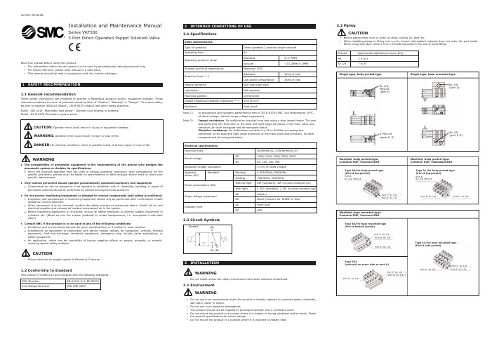
INSTALLATIONWARNINGDo not install unless the safety instructions have been read and understood.3.1EnvironmentWARNINGDo not use in an environment where the product is directly exposed to corrosive gases, chemicals,salt water , water or steam.Do not use in an explosive atmosphere.The product should not be exposed to prolonged sunlight. Use a protective cover Do not mount the product in a location where it is subject to strong vibrations and/or shock. Check the product specifications for above ratings.Do not mount the product in a location where it is exposed to radiant heat.Installation and Maintenance ManualSeries VKF3003 Port Direct Operated Poppet Solenoid ValveXSymbol(A)21(P)3(R)Rc 1/8(port A)Rc 1/8,M5x0.8(port A)2-M5x0.8(ports P , R)Rc 1/8(port P , R)Port A:Rc 1/8, M5x0.8Port R: Rc 1/8Port P: Rc 1/8Type 21/for body ported type (Port A top ported)Port A:Rc 1/8, M5x0.8Port P: Rc 1/8Type 20/for body ported type (Port A top ported)Port R: Rc 1/8Manifold, base mounted mon SUP, Common EXHPort R: Rc 1/8Type 42/for base mounted type (Port A side ported)Port P: Rc 1/8Type 40/for base mounted type (Port A bottom ported)Port R: Rc 1/8Port P: Rc 1/8Port A: Rc 1/8Port A: Rc 1/8Type S42(solenoid on same side as port A)Port P: Rc 1/8Port R: Rc 1/8Port A: Rc 1/8Use of DIN ConnectorLoosen the holding screw, and pull the connector out of the solenoid valve terminal block.After removing the holding screw, insert the flat head screw driver , etc. into the notch on the bottom of the terminal block and pry it up, separating the Loosen the terminal screws (slotted screws) on the terminal block, insert the core of the leadThe connector should be inserted and pulled out in a straight line without tilting diagonally. Circuit diagram for connector with lightSMC products have been lubricated for life at manufacturer , and do not require lubrication in If a lubricant is used in the system, use turbine oil Class 1(no additive), ISO VG32. Once lubricant is used in the system, lubrication must be continued because the original lubricant applied during When the manual override is operated, connected equipment will be actuated. Not following proper procedures could cause the product to malfunction and could lead to damage f handled improperly, compressed air can be dangerous. Assembly, handling and repair of pneumatic system should be performed by qualified personnel only.Drain: remove condensate from the filter bowl on a regular basis.Shut-down before maintenance: before attempting any kind of maintenance make sure the supply pressure is shut off and all residual air pressure is released from the system to be worked on.Start-up after maintenance: apply operating pressure and power to the equipment and check for f operation is abnormal, please verify product set-up Do not disassemble the product, unless required by installation or maintenance instructions.Refer to paragraph 3.4, for mounting valves onto manifolds.Operation is possible to -10°C, but measures should be taken to avoid solidification or freezing of drainage Telephone(39) 02-92711 Netherlands (31) 20-531 8888 (47) 67 12 90 20 (48) 22-548 50 85 (351) 22 610 89 22(34) 945-18 4100 (46) 8-603 0700 Switzerland (41) 52-396 3131 (90) 212 221 1512 United Kingdom(44) 1908-56 3888Red (+)Black (-)Surge voltage suppressor* MarkingLight(built into connectorSurge voltage suppressor (built intoterminal block)* MarkingsFor 24V or more DCFor AC and 12V or less DC1(-)(+)2Gland nut Washer Grommet (rubber)Holding screw Light mounting location Terminal blockNotchTerminal screw (3 places)Rating symbol (see table below)HousingACCircuit diagram12VDC or less Circuit diagram24VDC or more Circuit diagramLEDNLRLEDRR222111NL: Neon light R: ResistorLED: Light emitting diodeR: ResistorD: Protective diode LED: Light emitting diodeR: ResistorMounting screwBushingSwitching elementValveOFF Leakage currentPower supplyResistorL e a k a g e v o l t a g eHole dia. ø5ø9D。
电磁阀ESV-S D系列使用说明书
Instruction and OperatingManualSolenoid ValveESV-S/D SeriesPower-Genex Ltd.1. Introduction1.1General InformationThis instruction and operating manual contains important notices the user should observe for a personal safety as well as for prevention against damage to property. Notices concerning a personal safety are highlighted by a safety alert symbol ().1.2General Safety InstructionsThis product was delivered out from the factory without any safety problems after a strict quality management process. In order to maintain this status and ensure a safe operation of this product, please be sure to read all safety instructions carefully described in this manual and observe safety information and symbols without exception.1.3 Correct Usage① This product can be used only for purposes specified in these instructions. If they are notdefinitely stated in these instructions, the user is fully responsible for all changes and retrofits to this product.② This product is the electrostatic sensitive device that may be seriously damaged by voltagesundetectable to a human. These kinds of voltages occur as soon as a electronic component or an assembly is touched by a person who is not grounded against a static electricity.Damage to a electronic component as a result of overvoltage cannot usually be detected immediately. It may become apparent after a long period of operation. Therefore, please make sure to avoid electrostatic charge.1.4 Range and Responsibilities of Personnel① Qualified personnel should be trained, instructed or authorized in operating and maintainingproducts and systems according to the safety regulations for electrical circuits, high voltages and hazardous atmosphere.② For explosion proof products, they should be trained, instructed or authorized in carrying outwork on electrical circuits for hazardous systems.③ They should be trained or instructed in maintenance and use of proper safety equipmentaccording to the safety instructions.④ They should have a good experience to identify risks and avoid potential hazards whenworking with these products and systems.1.5 Transport and StorageMake sure that damages during delivery are prevented through proper packaging.Products and replacement parts should be returned in their original packaging. If the original packaging is no longer available, please ensure that they should be packaged to provide sufficient protection against transport.2. SpecificationsSingle CoilDual CoilESV-SESV-SSESV-DESV-DSOperating Air pressure 1.5 ~ 10 bar Supply Air Pressure (Max.) 15 bar Operating Voltage : CurrentAC 220V : 17mA AC 110V : 55mA DC 24V : 138mAVoltage Tolerance ±10%Explosion proof class Exd IIC T6 (KC-certified)Operating Ambient Temp.-20 ~ +60℃Flow Capacity(Cv) 0.9Mounting Configuration NAMUR or screw interfacePneumatic Connections PT 1/4 or NPT 1/4 Electrical Connections G 1/2, NPT 1/2 or M20Coil Insulation GradeClass F or H Duty Cycle 100%Material (body)Aluminum 316SS Aluminum 316SS Weight0.9Kg1.9Kg1.4Kg2.5Kg3. Part Numbering System (order code)Model No.ESV - x xX XCoil(s)Single coilS Dual coilsDMaterialAluminum . 316SS SOperating VoltageAC 220 A220 AC 110 A110 DC 24D24Connections (Pneumatic -Electrical)Rc 1/4 - G1/2 P NPT 1/4 - NPT 1/2N4. Principle of Operation1) If power is on a magnetic force is created around coils.2) The armature core (10) is moved to and blocks the armature vent body (20). 3) A supply air pushes a spool through the orifice body (3) and vents out from Port 4. 4) If a voltage is not supplied, a magnetic force around coils disappears.5) A supply air from the orifice body (3) is blocked by a spring between the armature seat (18) and the armature core (10).6) A supply air pushes the spool from the bottom through an air line at the center, and air remaining in the orifice body (3) vents out from the vent body (20). 7) Eventually, a supply air vents out from Port 2 when power is off.5. Manual SwitchThe ESV solenoid valve can be operated by this switch manually while air is supplied. - Ininitial setting “0” : the ESV solenoid valve works with a power voltage. - Manual operation “1” : Port 4 is open regardless of a power voltage.When power is off and the manual switch is positioned to “0”, Port 2 becomes open. When the manual switch is postioned to “1”, Port 4 becomes open.“0”“1”Note that the manual switch is not active when power is off.<Power On / Activated><Power Off / Normal>6. InstallationAs the ESV solenoid valve is designed for NAMUR mounting pattern, it can be mounted directly onto the pneumatic actuator without an additional piping. Also, as it has Rc 1/4 or NPT 1/4threads inside of the connections as standard, the screw interface is available.<Single coil type><Dual coils type>7. Electrical ConnectionsThe ESV solenoid valve head can be rotated by 90° to the right or to the left for an optimal mounting as shown below.① Supply the rated voltage and current stated on this manual. Otherwise, it may cause a serious damage or malfunctions.② Observe all explosion proof regulations required in the area.. ③Earth internally and externally before using.8. Spare PartsNo. Description No.Description1 Valve Body 15 Orifice Body Bolt2 Valve Body Cover 16 Valve Body Cover Bolt3 Orifice Body 17 Armature Seat Ring4 Coil Box Body 18 Armature Seat Bolt5 Coil Box Cover 19 Armature Seat Tube6 Terminal Box Cover 20 Armature Vent Body7 Terminal Box 21 Solenoid Coil Bobbin8 Valve Spool 22 Solenoid Coil9 Orifice 23 Solenoid Coil Cover10 Armature Core 25 Terminal Box Bolt11 Stop Pin 26 Ground Bolt12 Stop Pin Spring 27 Air Vent13 Auto-Manual Switch14 Auto-Manual Switch Stop Pin9. Dimensions 9.1 ESV-S9.2 ESV-DPower-Genex Ltd. 99, Eunbong-ro, Namdong-gu, Incheon 405-849 Korea Tel : +82-32-812-6644Fax : +82-32-812-6645Website : E-mail : ********************Subject to change without prior notice。
电磁阀使用说明书
电磁阀使用说明书使用说明书一、产品介绍电磁阀是一种常用的自动控制元件,广泛应用于工业、农业、冶金、电力等领域。
本使用说明书旨在帮助用户正确使用电磁阀,确保其正常运行及延长使用寿命。
二、技术参数1. 工作电压:一般为220VAC,也可根据需要定制其他电压。
2. 工作压力:常见工作压力为0.1MPa-1.6MPa,也可根据实际需求定制其他工作压力。
3. 工作温度:一般为-10℃至80℃,也可根据使用环境要求定制其他工作温度范围。
三、安装及操作1. 安装前请仔细查看产品外观是否完好,避免安装损坏。
2. 电磁阀安装时应垂直放置,避免倾斜或颠倒安装,以确保正常通电操作。
3. 进口与出口接口请使用合适的密封材料,以防止漏气现象的发生。
4. 连接导线时,请确保电源线与电磁阀的接线端正好对应,并紧固好螺丝。
5. 操作时,请遵循以下步骤:a. 检查电磁阀与相关设备的电源线是否连接正常。
b. 检查电磁阀与相关设备的电源开关是否打开。
c. 通过控制开关或按钮来操作电磁阀开关,确保其正常开闭。
四、维护保养1. 保持电磁阀的清洁,避免污物进入影响正常运行。
2. 定期检查电磁阀的电源线及接线端是否松动,如有松动请及时拧紧。
3. 若发现电磁阀工作异常,请立即停止使用,并联系专业人员进行维修。
五、注意事项1. 请勿私自拆解电磁阀,以免造成损坏或安全事故。
2. 使用过程中请勿随意更改产品的工作电压、工作压力或工作温度范围,以免影响产品性能。
3. 遇到雷暴天气或长时间不使用时,请切断电源并将电磁阀垂直存放。
六、故障排除以下情况可能会导致电磁阀故障,请参考以下步骤进行排查:1. 电磁阀无法开启:a. 检查供电电源是否正常。
b. 检查控制开关或按钮是否正常。
c. 检查电磁阀的接线是否正确连接。
d. 若仍无法解决,请联系售后服务部门。
2. 电磁阀无法关闭:a. 检查供电电源是否正常。
b. 检查控制开关或按钮是否正常。
c. 检查电磁阀的接线是否正确连接。
电磁阀详细说明
电磁阀详细说明--------------------------------------------------------------------------------电磁阀是用来控制流体的自动化基础元件,属于执行器;并不限于液压,气动。
电磁阀用于控制液压流动方向,工厂的机械装置一般都由液压钢控制,所以就会用到电磁阀。
工作原理电磁阀里有密闭的腔,在的不同位置开有通孔,每个孔都通向不同的油管,腔中间是阀,两面是两块电磁铁,哪面的磁铁线圈通电阀体就会被吸引到哪边,通过控制阀体的移动来档住或漏出不同的排油的孔,而进油孔是常开的,液压油就会进入不同的排油管,然后通过油的压力来推动油刚的活塞,活塞又带动活塞杆,活塞竿带动机械装置动。
这样通过控制电磁铁的电流就控制了机械运动。
分类直动式电磁阀:原理:通电时,电磁线圈产生电磁力把关闭件从阀座上提起,阀门打开;断电时,电磁力消失,弹簧把关闭件压在阀座上,阀门关闭。
特点:在真空、负压、零压时能正常工作,但通径一般不超过25mm。
分布直动式电磁阀:原理:它是一种直动和先导式相结合的原理,当入口与出口没有压差时,通电后,电磁力直接把先导小阀和主阀关闭件依次向上提起,阀门打开。
当入口与出口达到启动压差时,通电后,电磁力先导小阀,主阀下腔压力上升,上腔压力下降,从而利用压差把主阀向上推开;断电时,先导阀利用弹簧力或介质压力推动关闭件,向下移动,使阀门关闭。
特点:在零压差或真空、高压时亦能可*动作,但功率较大,要求必须水平安装。
先导式电磁阀:原理:通电时,电磁力把先导孔打开,上腔室压力迅速下降,在关闭件周围形成上低下高的压差,流体压力推动关闭件向上移动,阀门打开;断电时,弹簧力把先导孔关闭,入口压力通过旁通孔迅速腔室在关阀件周围形成下低上高的压差,流体压力推动关闭件向下移动,关闭阀门。
特点:流体压力范围上限较高,可任意安装(需定制)但必须满足流体压差条件选择使用时需要注意的特性一. 安全性:1.腐蚀性介质:宜选用塑料王电磁阀和全不锈钢;对于强腐蚀的介质必须选用隔离膜片式。
伊莱克斯电磁阀说明书
外 形 尺 寸 OV E R ALL DIM E N S IO N S (m m )
FG6 Rp 2"
56
2/ 6 208 128 182 2000 330
C
GAS FLOW CHART (PRESSURE DROP)
A C
B B
A
Description The VMR type is a fast opening and fast closing solenoid valve that is normally closed. When not energized the spring works on the seat keeping the gas passage closed. When the coil is powered the valve is rapidly opened.If the power supply is shut off,the valve rapidly closed.
FLOW FACTOR
KVS(m 3/h)
VM R 01--OT N VM R 02--OT N VM R 12--OT N
VMR0 VM R 12-A
VMR1 VMR2 VMR3 VM R35 VMR4 VMR6 VM R4F VM R6F VMR7 VMR8 VMR9 VM R93 VM R95
-
-
2.50
- 1、下载文档前请自行甄别文档内容的完整性,平台不提供额外的编辑、内容补充、找答案等附加服务。
- 2、"仅部分预览"的文档,不可在线预览部分如存在完整性等问题,可反馈申请退款(可完整预览的文档不适用该条件!)。
- 3、如文档侵犯您的权益,请联系客服反馈,我们会尽快为您处理(人工客服工作时间:9:00-18:30)。
May 2009-04
D 7915 page 2
D 7915 page 3
D 7915 page 4
D 7915 page 5
Special voltage
The table below lists all voltage available incl. the one listed on page 2.Notes to the lay-out:
DC-voltage:
The voltage specification (solenoid lay-out) shall correspond to the actual supply voltage (perm. tolerance ± 5...10%).
A reduced voltage leads to reduced solenoid force, an exceeded voltage causes an unper-missible solenoid heat built-up.
AC-voltage:
The voltage specification shall correspond to the actual supply voltage (50/60 Hz).
The solenoid DC-voltage is approx. 0.9 U AC -2V because of the utilized rectifier plug. The table above lists the corresponding DC-solenoids for various AC supply volt-age (e.g. for 110V AC 50 Hz, solenoid with U N = 98V DC & stamping on the solenoid!).
Examples: VP1 - R - G 48 VP 1 - Z - X 110
VP 1 - W - WG 200
The specified power ratings are only guide line figures, they may vary slightly depending on voltage and manufacturer. The cold current can be calculated: I 20 = P N /U N (see examples)G 12G 24G 36G 42G 48G 80G 98G 110G 125G 185G 205G 220
GM 12GM 24GM 36GM 42GM 48GM 80GM 98GM 110
GM 205GM 230
WG 24WG 42WG 48
WG 110WG 200WG 230
WGM 24WGM 42WGM 48
WGM 110
WGM 230
G 24 EX
P , 26,5 W DC (& U N [V ])P , 20 W Voltage specification
P , 28 W AC 50/60 Hz
P , 20 W Explosion proof version P , 23 W 2.2.2 Further actuation modes Hydraulic (coding H)
The actuation element is a single acting control piston with spring return.
The switching position is maintained as long as the control pressure is applied. The valve will return automatically to its idle position (0) when the control pressure is removed. The control piston is sealed and shows zero leakage. Means of control Oil Control pressure max = 700 bar min = 12 bar Control displacement 0.4 cm 3
Temperature -40 ... +80°C (ambient and control fluid)
Pneumatic
(coding P)
The actuation element is a single acting control piston with spring return.
The switching position is maintained as long as the control pressure is applied. The valve will return automatically to its idle position 0 when the control pressure is removed. The control piston is sealed and shows zero leakage.
Means of control Compessed air, lubed and filtered Control pressure max =15 bar min = 4 bar Control displacement 1.0 cm 3
Temperature -20 ... +70°C (ambient and compressed air)
Mechanic
(coding K and T) The actuation element is a pin with spring return. This pin is either directly actuated or via lever with roller following a cam. Switching position a of the valve is achieved when the pin is pressed down (see dimensional drawing sect. 3.2).
Actuation force = 25 ... 28 N (coding K)
= 51 ... 57 N (coding T)
Actuation travel
see dimensional drawing sect. 3.2
Manual (coding F)
The actuation element is a lever acting on a pin with spring return. Switching position a of the valve is achieved when the pin is pressed down. A ctuation force = 25 ... 28 N
Actuation travel
see dimensional drawing sect. 3.2
(coding D)
Actuation with detent. The achieved switching position a or 0 changes with every 90° turn, no matter of the rotation direction. Actuation torque = 63 Ncm
Actuation travel
see dimensional drawing sect. 3.2
D 7915 page 6
D 7915 page 7
D 7915 page 8。