GSR电磁阀说明书
G3VM-21AR DR MOS FET 关联型电磁阀说明书
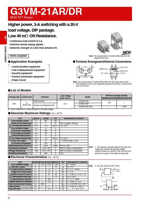
G3VM-21AR/DR Higher power, 3-A switching with a 20-Vload voltage, DIP package.Low 40 mΩ ON Resistance.•Continuous load current of 3 A.•Switches minute analog signals.•Dielectric strength of 2,500 Vrms between I/O.■Application Examples■Terminal Arrangement/Internal Connections■List of Models*The AC peak and DC value are given for the load voltage.■Absolute Maximum Ratings (Ta = 25°C)RoHS compliant Note: The actual product is marked differently from theimage shown here.•Communication equipment•Test & Measurement equipment•Security equipment•Factory Automation equipment•Power circuitOMRON logoPin 1 markModel nameMold pin mark ∗LOT No.Note: The actual product is marked differently from the image shown here.∗The indentation in the corner diagonally opposite from the pin 1 mark is froma pin on the mold.Package type Contact form TerminalsLoad voltage(peak value) *ModelMinimum package quantityNumber per stick Number per tape and reel DIP41a(SPST-NO)PCB terminals20 VG3VM-21AR100---Surface-mounting terminalsG3VM-21DRG3VM-21DR (TR)---1,500 Item Symbol Rating Unit Measurement conditionsInputLED forward current I F30mANote: 1. The dielectric strength between the input andoutput was checked by applying voltagebetween all pins as a group on the LED side andall pins as a group on the light-receiving side.Repetitive peak LED forward current I FP 1 A100µs pulses, 100 ppsLED forward current reduction rate∆I F/°C−0.3mA/°C Ta ≥ 25°CLED reverse voltage V R 5 VConnection temperature T J125 °COutputLoad voltage (AC peak/DC)V OFF20VContinuous load current (AC peak/DC)I O3AON current reduction rate∆I O/°C−30 mA/°C Ta ≥ 25°CPulse ON current Iop9A t = 100 ms, Duty = 1/10Connection temperature T J125 °CDielectric strength between I/O (See note 1.)V I-O2500Vrms AC for 1 minOperating temperature Ta −40 to +85°C With no icing or condensationStorage temperature Tstg−55 to +125°C With no icing or condensationSoldering temperature---260 °C10 s12G3VM-21AR/DRMOS FET RelaysG3VM-21AR/DR■Recommended Operating ConditionsUse the G3VM under the following conditions so that the Relay will operate properly.■Engineering Data■Safety Precautions•Refer to "Common Precautions" for all G3VM models.ItemSymbol MinimumTypical MaximumUnit Load voltage (AC peak/DC)V DD ------16V Operating LED forward current I F 51025mA Continuous load current (AC peak/DC)I O ------3AOperating temperatureTa−20 ---65 °CLED forward current vs.Ambient temperatureContinuous load current vs.Ambient temperatureLED forward current vs.LED forward voltageContinuous load current vs.On-state voltageOn-state resistance vs.Ambient temperatureTrigger LED forward current vs.Ambient temperatureTurn ON, Turn OFF time vs.LED forward currentTurn ON, Turn OFF time vs.Ambient temperatureCurrent leakage vs.Ambient temperatureI F - TaAmbient temperature Ta (°C)L E D f o r w a r d c u r r e n t I F (m A )03010204050-40100806040200-20I O - TaAmbient temperature Ta (°C)C o n t i n u o u s l o a d c u r r e n t I O (A )-40100806040200-2004321I - V LED forward voltage V F (V)0.01L E D f o r w a r d c u r r e n t I F(m A )I O - V ONOn-state voltage V ON (V)-4-3-2-1C o n t i n u o u s l o a dc u r r e n t I O (A )R - Ta60204080100Ambient temperature Ta (°C)O n -s t a t e r e s i s t a n c e R O N (m Ω)I FT - TaAmbient temperature Ta (°C)012T r i g g e r L E D f o r w a r d c u r r e n t I F T (m A )t , t - ILED forward current I F (mA)0.010.110100T u r n O N , T u r n O F F t i m e t O N , t O F F (m s )t, t - TaAmbient temperature Ta (°C)T u r n O N , T u r n O F F t i m e t O N , t O F F (m s )I LEAK - TaAmbient temperature Ta (°C)0.011001010.1C u r r e n t l e a k a g e I L E A K (n A )■Dimensions(Unit: mm) Note: The actual product is marked differently from theimage shown here.PCB Dimensions (Bottom View)Actual Mounting Pad Dimensions(Recommended Value, Top View)Note: The actual product is marked differently from the image shown here.∗ The indentation in the corner diagonally opposite from the pin 1 mark is from a pin on the mold.+0.1−0.05PCB TerminalsWeight: 0.25 gSurface-mounting TerminalsWeight: 0.25 g• Application examples provided in this document are for reference only. In actual applications, confirm equipment functions and safety before using the product.• Consult your OMRON representative before using the product under conditions which are not described in the manual or applying the product to nuclear control systems, railroad systems, aviation systems, vehicles, combustion systems, medical equipment, amusement machines, safety equipment, and other systems or equipment that may have a serious influence on lives and property if used improperly. Make sure that the ratings and performance characteristics of the product provide a margin of safety for the system or equipment, and be sure to provide the system or equipment with double safety mechanisms.Cat. No. K135-E1-020412(0412)(O)Note: Do not use this document to operate the Unit. OMRON CorporationELECTRONIC AND MECHANICAL COMPONENTS COMPANY Contact: /ecb。
电磁阀使用说明书(1)

~~
...;
5-_.J.. ~
- - ~ , "~ IS Il
, ., '0 , 2
15 • til 1111 . 1'"
fi g.1S
numalUL "1"_* AStli
II' ~.. ( t.l!» 'IAt~l'l I' ll· tlI retr~ I'IUlJiTlli=!& 4BO ,
N..I1I../IInOf/ lila jj lUi t l Ji:I *CI!'lbI:lIIn J!I.• •11'I!!"tfJI~fTtI,..i. S/l&.;/l Ulilf I"II'A
tmJ"''''!IiI!ttI. lin!'!'" iI/!!-ltJ SI2~ li'IlIJU
, 20 1612
'1110\ , (86·21 }57071888
, 800·820·2323
lilt;: www.ascoval\le. net
@
3834907 R1 'I-;.l o iil . JL 1O .j!
Ir.staJtat~ and Maintenance InstrtJC/tJn s
• •~~~"t~~~~~~OlC• • i.i.tilF'" n . JIll!! 2 -SI1.SlJ U, \ '1 _'t-"IIllt!!l1 0, ~I~ I...., "I!IIl&I1.lt"t lIlltllll*illl ][1111' c (q-I·' Sll WIW'
电磁阀商品说明书

3.70 OHMS 14.9 OHMS 60.5 OHMS 1530 OHMS 6120 OHMS
DC COILS 6 VDC
12 VDC 24 VDC 110 VDC
53648-80 53648-81 53648-83 53648-93
10.5 OHMS 42 OHMS
167 OHMS 3400 OHMS
PLUNGER CONE ANGLE (DC): 60 degrees (standard) also available flat, 90 degrees, custom
MAXIMUM DIMENSIONS:
Length
.783 In.
Width
.702 In.
Height
.780 In.
Plunger Diameter ø.315 In.
NOTE: Approx. 36 sq. in. Heat Sink Required.
15
DIMENSIONS
C-4 “C” FRAME SOLENOID
COIL TREATMENT: Tape Wrapped. Class A Rating (standard)
MAXIMUM OPERATING TEMPERATURE: Class A – 105°C (221°F)
பைடு நூலகம்
DIELECTRIC STRENGTH: 30 Volts and Under: 500 VRMS Over 30 Volts: 1,000 VRMS plus 2x rated voltage for one minute
MAXIMUM STROKE: .300 In.
C-4 STANDARD COIL RATING
电磁阀的使用说明
电磁阀的使用说明选型要领:电磁阀选型首先应该依次遵循安全性,可靠性,适用性,经济性四大原则,其次是根据六个方面的现场工况(即管道参数、流体参数、压力参数、电气参数、动作方式、特殊要求进行选择)。
选型依据:一、根据管道参数选择电磁阀的:通径规格(即DN)、接口方式1、按照现场管道内径尺寸或流量要求来确定通径(DN)尺寸。
2、接口方式,一般>DN50要选择法兰接口,≤DN50则可根据用户需要自由选择。
二、根据流体参数选择电磁阀的:材质、温度组1、腐蚀性流体:宜选用耐腐蚀电磁阀和全不锈钢;食用超净流体:宜选用食品级不锈钢材质电磁阀。
2、高温流体:要选择采用耐高温的电工材料和密封材料制造的电磁阀,而且要选择活塞式结构类型的。
3、流体状态:大至有气态,液态或混合状态,特别是口径大于DN25订货时一定要区分开来。
4、流体粘度:通常在50cSt以下可任意选择,若超过此值,则要选用高粘度电磁阀。
三、根据压力参数选择电磁阀的:原理和结构品种1、公称压力:这个参数与其它通用阀门的含义是一样的,是根据管道公称压力来定。
2、工作压力:如果工作压力低则必须选用直动或分步直动式原理;最低工作压差在0.04Mpa以上时直动式、分步直动式、先导式均可选用。
四、电气选择:电压规格应尽量优先选用AC220V、DC24较为方便。
五、根据持续工作时间长短来选择:常闭、常开、或可持续通电1、当电磁阀需要长时间开启,并且持续的时间多余关闭的时间应选用常开型。
2、要是开启的时间短或开和关的时间不多时,则选常闭型。
3、但是有些用于安全保护的工况,如炉、窑火焰监测,则不能选常开的,应选可长期通电型。
六、根据环境要求选择辅助功能:防爆、止回、手动、防水雾、水淋、潜水1、爆炸性环境:必须选用相应防爆等级的电磁阀2、当管内流体有倒流现象时,可选择带止回功能电磁阀。
3、当需要对电磁阀进行现场人工操作时,可选择带手动功能电磁阀。
4、露天安装或粉尘多场合应选用防水,防尘品种(防护等级在IP54以上)。
60 G3VM-41GR6 MOS FET 电磁阀说明书
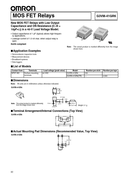
G3VM-41GR6MOS FET RelaysNew MOS FET Relays with Low Output Capacitance and ON Resistance (C ×R = 10pF •Ω) in a 40-V Load Voltage Model.•Output capacitance of 1 pF (typical) allows high-frequen-cy applications.•Leakage current of 1.0 nA max. when output relay is open.RoHS compliant!■Application Examples•Semiconductor inspection tools •Measurement devices •Broadband systems •Data loggersNote:The actual product is marked differently from the image shown here.■List of Models■DimensionsNote:All units are in millimeters unless otherwise indicated.■Terminal Arrangement/Internal Connections (Top View)■Contact form Terminals Load voltage (peak value)ModelNumber per stick Number per tape SPST-NOSurface-mounting terminals40 VACG3VM-41GR6100---G3VM-41GR6(TR)---2,500G3VM-41GR6Note:The actual product is marked differentlyfrom the image shown here.Weight: 0.1 gG3VM-41GR6G3VM-41GR6G3VM-41GR6G3VM-41GR6■Absolute Maximum Ratings (Ta = 25°C)■Electrical Characteristics (Ta = 25°C)■Recommended Operating ConditionsUse the G3VM under the following conditions so that the Relay will operate properly.■Engineering DataLoad Current vs. Ambient TemperatureG3VM-41GR6■Safety PrecautionsRefer to “Common Precautions” for all G3VM models.ItemSymbol Rating Unit Measurement ConditionsInputLED forward currentI F 50mARepetitive peak LED forward currentI FP1A 100 µs pulses, 100 pps LED forward current reduction rate∆ I F /°C −0.5mA/°C Ta ≥ 25°CLED reverse voltage V R 5V Connection temperatureT j 125°C OutputOutput dielectric strength V OFF 40V Continuous load current I O 120mA ON current reduction rate ∆ I ON /°C −1.2mA/°C Ta ≥ 25°CConnection temperatureT j 125°C Dielectric strength between input and output (See note 1.)V I-O 1,500Vrms AC for 1 minOperating temperature T a −20 to +85°C With no icing or condensation Storage temperature T stg −55 to +125°C With no icing or condensation Soldering temperature (10 s)---260°C10sNote:1.The dielectric strength between the input andoutput was checked by applying voltage be-tween all pins as a group on the LED side and all pins as a group on the light-receiving side.ItemSymbol Mini-mum Typical Maxi-mum UnitMeasurement conditions InputLED forward voltage V F 1.0 1.15 1.3V I F = 10 mA Reverse currentI R ------10µA V R = 5 V Capacity between terminals C T ---15---pF V = 0, f = 1 MHz Trigger LED forward currentI FT ------4mA I O = 100 mA OutputMaximum resistance with output ON R ON ---1015ΩI F = 5 mA,I O = 120 mA, t < 1 s Current leakage when the relay is openI LEAK ------ 1.0nA V OFF = 30 V, Ta = 50°C Capacity between terminalsC OFF --- 1.0 2.0pF V = 0, f = 100 MHz, t < 1 sCapacity between I/O terminals C I-O ---0.8---pF f = 1 MHz, Vs = 0 V Insulation resistance R I-O 1,000------M ΩV I-O = 500 VDC, RoH ≤ 60%Turn-ON time tON ------0.5ms I F = 10 mA, R L = 200 Ω, V DD = 20 V (See note 2.)Turn-OFF timetOFF------0.5ms Note:2.Turn-ON and Turn-OFFTimesItemSymbol MinimumTypicalMaximumUnitOutput dielectric strength V DD------32V Operating LED forward current I F 10---30mA Continuous load current I O ------120mA Operating temperatureT a25---60°CCommon Precautions!WARNINGBe sure to turn OFF the power when wiring the Relay, other-wise an electric shock may be received.!WARNINGDo not touch the charged terminals of the SSR, otherwise an electric shock may be received.!CautionDo not apply overvoltage or overcurrent to the I/O circuits of the SSR, otherwise the SSR may malfunction or burn.!CautionBe sure to wire and solder the Relay under the proper soldering conditions, otherwise the Relay in operation may generate ex-cessive heat and the Relay may burn.Typical Relay Driving Circuit ExamplesUse the following formula to obtain the LED current limiting resis-tance value to assure that the relay operates accurately.Use the following formula to obtain the LED forward voltage value to assure that the relay releases accurately.Protection from Surge Voltage on the Input TerminalsIf any reversed surge voltage is imposed on the input terminals, insert a diode in parallel to the input terminals as shown in the fol-lowing circuit diagram and do not impose a reversed voltage value of 3V or more.Surge Voltage Protection Circuit ExampleProtection from Spike Voltage on the Output TerminalsIf a spike voltage exceeding the absolute maximum rated value isgenerated between the output terminals, insert a C-R snubber or clamping diode in parallel to the load as shown in the following circuit diagram to limit the spike voltage.Spike Voltage Protection Circuit ExampleUnused Terminals (6-pin models only)Terminal 3 is connected to the internal circuit. Do not connect anything to terminal 3 externally.Pin Strength for Automatic Mountingn order to maintain the characteristics of the relay, the force imposed on any pin of the relay for automatic mounting must not exceed the following.In direction A: 1.96 NIn direction B: 1.96 NLoadTransistor10 to 100 kΩLoadR1 =V CC− V OL− V F (ON) 5 to 20 mAV F (OFF) = V CC− V OH < 0.8 VLoad ConnectionDo not short-circuit the input and output terminals while the relay is operating or the relay may malfunction.Solder MountingPerform solder mounting under the following recommended con-ditions to prevent the temperature of the Relays from rising.<Flow Soldering>Through-hole Mounting (Once Only)Note:We recommend that the suitability of solder mounting be verified under actual conditions.<Reflow Soldering>Surface Mounting DIP or SOP Packages (Twice Max.) Surface Mounting SSOP Packages (Twice Max.)Note: 1.We recommend that the suitability of solder mounting be verified under actual conditions.2.Tape cut SSOPs are packaged without humidity resis-tance. Use manual soldering to mount them.Manual Soldering (Once Only)Manually solder at 350°C for 3 s or less or at 260°C for 10 s or less.SSOP Handling Precautions<Humidity-resistant Packaging>Component packages can crack if surface-mounted components that have absorbed moisture are subjected to thermal stress when mounting. To prevent this, observe the following precau-tions.1.Unopened components can be stored in the packaging at 5to 30°C and a humidity of 90% max., but they should be used within 12 months.2.After the packaging has been opened, components can bestored at 5 to 30°C and a humidity of 60% max., but they should be mounted within 168 hours.3.If, after opening the packaging, the humidity indicator turnspink to the 30% mark or the expiration data is exceeded, bake the components while they are still on the taping reel, and use them within 72 hours. Do not bake the same com-ponents more than once.Baking conditions: 60±5°C, 64 to 72 hExpiration date: 12 months from the seal date(given on the label)4. f the same components are baked repeatedly, the tapedetachment strength will change, causing problems when mounting. When mounting using dehumidifying measures, always take countermeasures against component damage from static electricity.5.Do not throw or drop components. If the laminated packag-ing material is damaged, airtightness will be lost.6.Tape cut SSOPs are packaged without humidity resistance.Use manual soldering to mount them.AC ConnectionDC Single Connection DC Parallel Connection LoadLoadLoadLoadSolder type Preheating SolderingLead solderSnPb150°C60 to 120 s230 to 260°C10 s max.Lead-free solderSnAgCu150°C60 to 120 s245 to 260°C10 s max.Solder type Preheating SolderingLead solderSnPb140→160°C60 to 120 s210°C30 s max.Peak240°C max.Lead-free solderSnAgCu180→190°C60 to 120 s230°C30 to 50 sPeak260°C max.Solder type Preheating SolderingLead solderSnPb140→160°C60 to 120 s210°C30 s max.Peak240°C max.Lead-free solderSnAgCu150→180°C120 s max.230°C30 s max.Peak250°C max.。
Schneider Electric 电磁阀操纵器说明书
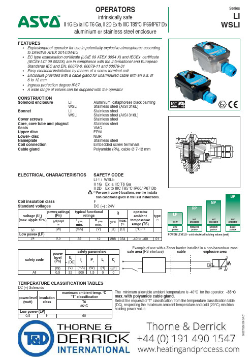
OPERATORSintrinsically safeII 1G Ex ia IIC T6 Ga, II 2D Ex tb IIIC T85°C IP66/IP67 Dbaluminium or stainless steel enclosureSeriesLI WSLI16/R 01FEATURES• Explosionproof operator for use in potentially explosive atmospheres according to Directive A TEX 2014/34/EU• EC type examination certificate (LCIE 09 ATEX 3054 X) and IECEx certificate (IECEx LCI 09.0022X) are in compliance with the International and European Standards IEC and EN: 60079-0, 60079-11 and 60079-31• Easy electrical installation by means of a screw terminal coil• Enclosure provided with a cable gland for unarmoured cable with an o.d. of 6 to 12 mm• Ingress protection degree IP67• A wide range of valves can be supplied with the operatorCONSTRUCTIONSolenoid enclosure LI Aluminium, cataphorese black painting WSLI Stainless steel (AISI 316L)Bonnet LI Stainless steel WSLI Stainless steel (AISI 316L)Cover screws Stainless steel Core, core tube and plugnut Stainless steel Seals VMQ Upper disc FPM Lower- disc N BR ameplate Stainless steel Coil connection Embedded screw terminals Cable gland Polyamide (P A), cable Ø 7-12 mmELECTRICAL CHARACTERISTICS SAFETY CODELI (1) / WSLI :II 1G Ex ia IIC T6 GaII 2D Ex tb IIIC T85°C IP66/IP67 Db!(1) For use in zone 0 locations, see the installa-tion conditions given in the I&M instructions.Coil insulation class FStandard voltagesDC (=) : 24Vvoltage (U n )(max. ripple 10%)power ratings(Pn)typical functionalratings R operator ambient temperature range (TS)type(3)hot/cold =I (ON)min.U (ON)min.20°C max.T6(V)(W)(mA)(V)(Ω)(Ω)(°C) (1)Low power (LP)240,53212288354-40 to +6001safety codepower level (Pn)safety parameters U i = (DC)I I P I L I C I (W)(V)(mA)(W)(H)(µF)All0,5325001,5TEMPERATURE CLASSIFICATION TABLESDC (=) Solenoids power level (watt)insulationclass maximum ambient temp. °C“T” classificationThe minimum allowable ambient temperature is -40°C for the operator. -35°C max. with polyamide cable gland.Select the requested "T" classification from the temperature classification table (DC), respecting the maximum ambient temperature and cold (20°C) electrical holding power value.T685°C Low power (LP)0,5F60BPMPRPLP0,5W Not available Not available Not available Low powerReduced powerMedium powerBasic powerPOWER LEVELS - cold electrical holding values (watt)ORDERING EXAMPLES VALVES:LI G 551B305MO 24VWSLI 8551A31324Vprefix pipe thread voltage basic numbersuffix16/R 01PRODUCT SELECTION GUIDE(The selection can only be made in conjunction with the appropriate valve catalogue sheet)STEP 1Select basic valve catalogue number, including pipe thread indentificationletter from one of the specification tables on the separate catalogue pages.Example: G551B305STEP 2Select voltage. Refer to standard voltages on page 1.Example: 24V / DC STEP 3Select solenoid prefix (combination). Refer to the prefix table on this page and respect the indicated power level, cold electrical holding values and "T" classification mentioned on page 1.NOTE: Make sure that the ambient temperature does not exceed the allowable valve temperature characteristics.Example: LI 60°C ambient L ow Power (LP) 0,5 W II 1G Ex ia IIC T6 Ga II 2D Ex tb IIIC T85°C IP67 Db STEP 4Final catalogue / ordering number. Example:LI G551B305 24V / DCPREFIX TABLEprefixdescriptionpower level 1234567LP RP MP BPL I I.S. with aluminium IP67 enclosure (EN/IEC 60079-11, -31)❍---W S LII.S. with 316L SS IP67 enclosure (EN/IEC 60079-11, -31)❍---XOther special constructions----❍ Available feature in DC only - Not availableADDITIONAL OPTIONS• C able glands (Nickel-plated brass): unarmoured cable, catalogue number 88200011 / armoured cable, catalogue number 88200014INSTALLATION• Multi language installation/maintenance instructions are included with each valve • The solenoid valves can be mounted in any position without affecting operation • Internal and external earthing connection• Electrical connection between solenoid valve and barrier/interface with cable type A or B according to EN 50039• The solenoid can be rotated 360° to select the most favourable position for cable entry16/R 01RECOMMENDED INTERFACESLocated in safe areas, these interfaces allow to feed the intrinsically safe solenoid valves located in explosive areas.This equipment must be ordered from its respective manufacturers, specifying that they are intended to feed intrinsically safe solenoid operators:LI / WSLI: II 1G Ex ia IIC T6 Ga, II 2D Ex tb IIIC T85°C IP66/IP67 DbINTERFACESmanufacturermodule type1G/2G T6IIC ABB DO910Sx Bartec 07-7331-2105/1000x 07-7331-2301/1100x GEORGIN BXNE701002x BXNE70100Ex G.M. InternationalD1040Q-2D1049S x D1042Q-2D5048S x D1043Q-2D5049S x D1048S -x MTLMTL 722+MTL 779x MTL 728+MTL 4524S x MTL 728P+-x Pepperl +FuchsKFD2-SL2-Ex1x KFD2-SL2-Ex1.B x KFD2-SL2-Ex1.LK x KFD2-SL2-Ex2x KFD2-SL2-Ex2.B x KCD0-SD-Ex1.1245x KFD0-SD2-Ex2.1245x LB-2103FB-2203x LB-2105FB-2205x LB-2112FB-2212x PHOENIX CONTACTMACX MCR-EX-SD-24-48-LP(-SP)x MACX MCR-EX-SD-21-60-LP(-SP)x PI-EX-SD-24-48x PI-EX-SD-21-60x Stahl9475/12-04-119175/20-14-11x 9475/12-04-219176/10-14-00x 9475/12-04-319176/20-14-00x 9475/32-04-129175/10-16-11x 9475/32-04-229175/20-16-11x 9475/32-04-729176/10-16-00x 9175/10-14-119176/20-16-00x 9001/01-280-100-101x 9002/13-280-110-001xINTERFACESmanufacturermodule type1G/2G T6IIC TurckMK72-S09-Ex0/24VDC x MC72-41Ex-T/24VDCx MC72-44Ex-Tx Siemens6ES7132-7RD11-0AB0 2 ways x 6ES7132-7RD21-0AB0x 6ES7132-7GD10-0AB0 2 ways x 6ES7132-7GD20-0AB0xZENER BARRIERSBartec07-7331-2301/1001x CEAGSB-3722x SB-2420x SB-3729x SB-3728x SB-0728x GEORGIN BZG728+x BZG2728+x BZG728P+x BZG2728P+x MTL MTL 722MTL 728Px MTL 728MTL 779x Pepperl +Fuchs Z728x Z728.Hx Z728.CLx Stahl 9001/01-199-150-101x 9001/01-280-085-101x 9001/01-280-100-101x 9001/01-280-110-101x In accordance with the zone classification and the national le-gislation of each country, apply the certification procedures for the connection of IS-rated products with associated equipment. All information subject to change without notice. All responsibility for the use of products from other suppliers and the possible modi-fications of their characteristics is disclaimed.-G B -- A v a i l a b i l i t y , d e s i g n a n d s p e c i fic a t i o n s a r e s u b j e c t t o c h a n g e w i t h o u t n o t i c e . A l l r i g h t s r e s e r v e d .16/R 01type prefix power level weight M6LI low power 0,56M6WSLI low power 1,17TYPE LI:Low powerPrefix "LI" SolenoidAluminium, cataphorese black painting IEC and EN: 60079-11, 60079-31II 1G Ex ia IIC T6 Ga, II 2D Ex tb IIIC T85°C IP66/IP67 DbTYPE WSLI:Low powerPrefix "WSLI" Solenoid Stainless steelIEC and EN: 60079-11, 60079-31II 1G Ex ia IIC T6 Ga, II 2D Ex tb IIIC T85°C IP66/IP67 DbDIMENSIONS (mm), WEIGHT (kg)SERIES LI/WSLI。
GSR强制先导阀

Stand/State:06/2010-AP-DB- Errors excepted, subject to change!GSR-MK 24 保留技术修改权利 Stand/State:04/2008GSR-MK-JK-DB-24TH 保留技术修改权利 - Errors excepted, subject to change!Stand/State:04/2008GSR-MK-JK-DB-27 保留技术修改权利 - Errors excepted, subject to change!--GSR-MK JK DB35 保留技术修改权利 - Errors excepted, subject to change!Stand/State:05/2010GSR-MK-JK-DB-43 保留技术修改权利 -Errors excepted, subject to change!Stand/State: 06/2008GSR-MK-JM-DB-43TM 保留技术修改权利 - Errors excepted, subject to change!零件单 - Parts listK1.1 阀体 / Valve body K2.1 上阀盖 / Bonnet *K3.1 先导座 / Pilot seat *K3.2 隔膜/ Diaphragm *K3.3 导向管 / Guiding insert *K3.4 先导轴 / Pilot spindle K3.6 螺钉 / Cylinder screw *K3.7 由令螺母 / Union nut *K3.8 O 形圈 / O-ring K3.10 丝堵 / Sealing plug K3.12 垫片 / Disk K3.13 阻尼螺钉/ Damping screw K3.15 过滤器 / Filter retainer *K3.19 O 形圈 / O-ring *K3.23 O 形圈 / O-ring *K3.24 O 形圈 / O-ring K3.25 滤网 / Strainer *K3.26 O 形圈 / O-ring *K3.27 六角螺栓 / Hexagon nut K3.28 六角螺栓 / Hexagon nut *K3.29 六角螺栓 / Hexagon nut *K3.30 O 形圈 / O-ring *K3.31 O 形圈 / O-ring *K3.33 弹簧 / Spring K5.1 电磁管/ Solenoid tube *K5.2 铁芯/ Solenoid plunger *K5.3 铁芯弹簧 / Plunger spring K5.4 压件 / Pressure piece K5.5 O 形圈 / O-ring K5.6 垫片 / Disk K5.7 螺钉 / Cylinder screw K5.8 六角螺栓 / Hexagon nut K5.9 滚纹压片 / Corrugated disk K6.1 电磁/ Solenoid K7.1 接线端子 / Plug型号 / Type D4321-D4323型号 / Type D4324 / D4325型号 / Type B4326 - B4328*= 备件包中的零件*=Part of the spare parts set.7.15.85.96.15.25.15.33.263.12.13.23.303.271.17.15.85.96.15.25.15.33.262.13.293.23.13.301.13.103.153.83.257.15.75.95.45.53.335.66.15.25.55.13.193.273.123.42.13.73.23.11.1调整阀门关闭时间 - SR (G5/4-G2标配)Device for adjustable close damping -SR (From G5/4-G2 standard)螺钉右旋: 阀门关闭速度变慢Screw to the right site :Valve closes slower 螺钉左旋: 阀门关闭速度变快Screw to the left site :Valve closes faster3.283.133.233.103.153.243.25视图 AA--GSR-MK JK DB49 保留技术修改权利 - Errors excepted, subject to change!Stand/State:04/2008GSR-MK-JK-49TH 保留技术修改权利 - Errors excepted, subject to change!Stand/State:05/2010-JK-DB-1/041- Errors excepted, subject to change!GSR-MK 保留技术修改权利 Stand/State:05/2010-JK--- Errors excepted, subject to change!GSR-MK DB 2/164 保留技术修改权利 。
DUNGS冬斯MB - ZR (DLE) B01电磁阀中文说明书
MB-ZR (DLE) B01# 229 3302 (16)M C . 版本 E d i t i o n 03.19 .号码 229 33Dr.-Ing. Karl-Günther Dalsaß,Geschäftsführer / Chief Operating Officer 总经理Urbach, 2018-04-213 (16)M C . 版本 E d i t i o n 03.19 .号码 229 3304 (16)M C . 版本 E d i t i o n 03.19 .号码 229 330GasMultiBloc ® zweistu-fi ge Betriebsweise T yp MB-ZR (DLE) B01NennweitenRp 1/2 - Rp 1 1/4GasMultiBloc ® two-stage operation T yp MB-ZR (DLE) B01Nominal diametres Rp 1/2 - Rp 1 1/4操作和安装说明燃气多功能复合调节器 二级工作方式MB - ZR (DLE) B01 型公称内径Rp 1/2 - Rp 1 1/4Max. BetriebsdruckMax. operating pressure 最大 工作压力p max.V1+V2 Klasse A, Gruppe 2V1+V2 Class A, Group 2V1+V2 A级2类nach / acc. / 根据EN 161SchutzartDegree of protection 保护程度IP 54 nach / acc. / 根据IEC 529 ( DIN 40 050)Familie 1 + 2 + 3Family 1 + 2 + 3系列 1 + 2 + 3Ausgangsdruckbereich Outlet pressure range 输出压力范围S 20 / S 22: 4 - 20 mbar (0,4 - 2 kPa)S 50 / S 52: 4 - 50 mbar (0,4 - 5 kPa)Druckwächter/ Pressure Switch/压力监控器T yp/T ype/型号GW…A5, GW…A2, NB…A2, ÜB…A2nach / acc. / 根据EN 1854FeinsiebFine-mesh sieve A级2类nach / acc. / 根据U n ~(AC) 220 V-15 % …- 230 V+10 %Einschaltdauer/Switch-on duration/ 开关时间 100 %fl e!在液化气设备中使用时,mb-ZR不得在低于0°C下运行。