电磁阀说明书
电磁阀使用说明书(1)

~~
...;
5-_.J.. ~
- - ~ , "~ IS Il
, ., '0 , 2
15 • til 1111 . 1'"
fi g.1S
numalUL "1"_* AStli
II' ~.. ( t.l!» 'IAt~l'l I' ll· tlI retr~ I'IUlJiTlli=!& 4BO ,
N..I1I../IInOf/ lila jj lUi t l Ji:I *CI!'lbI:lIIn J!I.• •11'I!!"tfJI~fTtI,..i. S/l&.;/l Ulilf I"II'A
tmJ"''''!IiI!ttI. lin!'!'" iI/!!-ltJ SI2~ li'IlIJU
, 20 1612
'1110\ , (86·21 }57071888
, 800·820·2323
lilt;: www.ascoval\le. net
@
3834907 R1 'I-;.l o iil . JL 1O .j!
Ir.staJtat~ and Maintenance InstrtJC/tJn s
• •~~~"t~~~~~~OlC• • i.i.tilF'" n . JIll!! 2 -SI1.SlJ U, \ '1 _'t-"IIllt!!l1 0, ~I~ I...., "I!IIl&I1.lt"t lIlltllll*illl ][1111' c (q-I·' Sll WIW'
24Vzs-20小口径电磁阀说明书

24Vzs-20小口径电磁阀说明书
1、安装前应参阅该产品的使用说明书,是否符合你的使用需求。
2、管路使用前应确保管道内无污垢无杂质等,流体介质不清洁的应在电磁阀的前端安装过滤器,以防止杂质进入阀芯影响电磁阀的正常使用。
3、电磁阀为单向工作方式,不能反转,阀体上箭头是管路流体的流动方向,必须保持一致。
4、电磁阀安装方式:阀体水平,线圈垂直向上,选择水平安装,以增长使用寿命。
5、电磁阀在低温结冰环境,需要重新工作时应对电磁阀进行加热处理,或设置保温措施。
6、电磁阀线圈引线连接好后,应确认接线是否牢固、可靠,连接电器元件触点不应有抖动,松动将引起电磁阀不工作。
7、电磁阀安装在需要连续生产工作的管路时,最好搭建旁路管路,便于电磁阀的检修,维护,避免给生产带来影响。
8、电磁阀使用短时间通电工作,连续通电线圈会发热,单次连续通电最好控制再1小时内。
西安汇源仪表阀门 SXDF系列 双向直动式电磁阀 说明书

双向直动式电磁阀SXDF-8~100系列常闭式SXDF-8K~100K 系列常开式BSXDF-8~100系列防爆型一、产品概述SXDF-8~100系列直动式双向电磁阀是我公司工程技术人员在参改国外同类产品的基础上自发研制成功的一种多功能高技术的自控阀门。
该产品具有结构紧凑,动作灵敏,性能可靠,特别是介质方向可任意流动,解决了目前国内外绝大多数电磁阀只允许介质单向流通的难题,可适用于工业及民用自控领域对管道中的介质进行快速切断及远程控制。
二、主要特点1、工作介质或正反方向流动:由于采用进出口平衡结构,介质压力互相抵消,故电磁阀可实现正反方向正常工作。
2、介质范围广:由于采用直动式,使用介质不需先导孔调整,故可实现气体、液体及各种油类同时使用。
3、无压差工作:由于电磁阀动作不受工作介质压力影响,只靠电磁铁吸力及复位弹簧共同作用。
故工作可靠、安全、迅速。
4、可直接用于真空管道中:由于采用了软密封方式,介质压力与复位弹簧力可均作用于阀口,所以关闭严密,内外泄漏量均高于行业标准最高要求。
5、流通面积大:易于克服通道结疤、堵塞等弊端。
三、工作原理当电磁线圈通电时,电磁铁产生吸力,克服弹簧力。
由于阀塞上、下介质压力相等互相抵消,故阀塞不受介质压力影响。
在铁芯的拉力作用下,阀塞被推离阀口,使阀门开启。
当电磁铁线圈断电后,同样阀塞处于平衡状态,电磁铁吸力消除,阀塞在复位弹簧力的作用下推到密封阀座上,使阀门紧密关闭。
四、主要技术参数公称通径 8 10 15 20 25 32 40 50 65 80 100连接方式 G1/4 G3/8 G1/2 法兰 G3/4法兰G1″法兰G11/4法兰G11/2法兰G2″ 法兰 四孔法兰 四孔法兰八孔法兰公称压力 1.6Mpa 介质压力 +1.0Mpa~ -0.8Mpa +0.8Mpa~ -0.6Mpa 工作温度 5℃~80℃ (特殊-20℃~+150℃)环境温度 -20℃~+60℃工作电压 AC220V 380V 110V DC24V 220V线圈功耗 70W 80W 120W 150W 防爆等级 ExdIICT4 适用介质 气体 燃气 水 轻油开关时间 ≤1S材 质 不锈钢 铸铁、铸钢、不锈钢螺纹式结构图(1)螺纹式外形尺寸(单位:mm )型号规格SXDF-8B SXDF-10B SXDF-15B SXDF-20 SXDF-25SXDF-32SXDF-40SXDF-50 备 注 连接方式 G 1/4″/G 3/8″/G 1/2″G 3/4″ G 1″ G11/4″ G11/2″ G2″长(L ) 69 73 100 115 120 168 宽(A ) 80 80 80 86 95 125 高(H ) 185 195 218 270 275 295 常开型高度增加40mm防爆型高度 增加35mm宽度加40mm(2)法兰型外形尺寸(单位:mm )型号规格 SXDF-15BF SXDF-20BF SXDF-25BF SXDF-32BF SXDF-40BFSXDF-50BF 备 注 连接方式 4孔法兰 4孔法兰 4孔法兰 4孔法兰 4孔法兰 4孔法兰 长(L ) 110 110 140 148 148 195 宽(A ) 95 105 115 135 145 160 高(H ) 225 235 260 335 340 360常开型高度增加40mm防爆型高度增加35mm(3)大口径法兰型外形尺寸(单位:mm )型号规格 SXDF-65FSXDF-80F SXDF-100F SXDF-125F SXDF-150F SXDF-200F 备 注 连接方式 4孔法兰 4孔法兰 4孔法兰 4孔法兰 4孔法兰 4孔法兰 长(L ) 290 310 350 400 480 600 宽(A ) 185 200 220 250 285 340 高(H ) 450 480 520 600 650 680 常开型高度增加40mm防爆型高度增加35mm H六、安装使用注意事项1、电磁阀安装时应选择振动较小的水平管道锻为宜,尽量远离弯道处,以防止水锤对阀芯的冲击。
4V210-08电磁阀说明书,电磁阀安装使用说明书,电磁阀说明书

RDPC电磁阀说明书 VALVE 使用维护须知:1.使用前注意检查元件在运输过程中是否损坏,然后安装使用。
2.安装时,请注意气体流动方向及接管是否正确。
3.安装时特别注意电压是否符合要求,整机调试时建议先用手动装置调试,然后再通电调试。
4.请注意防尘,使用清洁空气(气路前务必安装空气过滤器)建议排气口安装消声节流阀。
5.连接管路时,注意止泄带缠绕不可超过牙端面,并注意消除管接头、管子内的金属颗料、粉尘及油污等。
4V - 210 - 08 - AC220V 100系列200系列300系列400系列接管口径:04:M5*0.806:G1/8"08:G1/4"10:G3/8"15:G1/2"4V:五孔电磁阀4M:五孔板接式4A:五孔气动阀3V:三孔电磁阀形式:10:单线圈双位置20:双线圈双位置30C:双线圈三位置封闭型30E:双线圈三位置开放型30P:双线圈三位置压力型标准电压:DC12VDC24VDC36VAC110V 50/60HzAC220V 50/60HzAC380V 50/60Hz阀体及密封材质工作介质动作方式润滑工作压力最高耐压工作温度电压范围耗电量绝缘等级寿命最大功作频率励磁时间接线方式铝件处理工艺铝、丁青橡胶经40um过滤干净空气内部先导式无须润滑1.5~8.0kgf/cm²12kgf/cm²(1.2MPa)5~50℃+15~-25%AC:5.4VA DC:2.5WF级:IP65(可选防爆型)300万次以上每秒5次0.05秒引线式或端子式硬质氧化、喷漆4V210-08AC220VPressure:1.5~8kg/cm²宁波市荣大气动液压有限公司Ningbo rong large pneumatic hydraulic co., LTD 型号解读:工作参数:Ningbo rong large pneumatic hydraulic co., LTD。
SV6100系列2路阀门电磁阀产品说明书
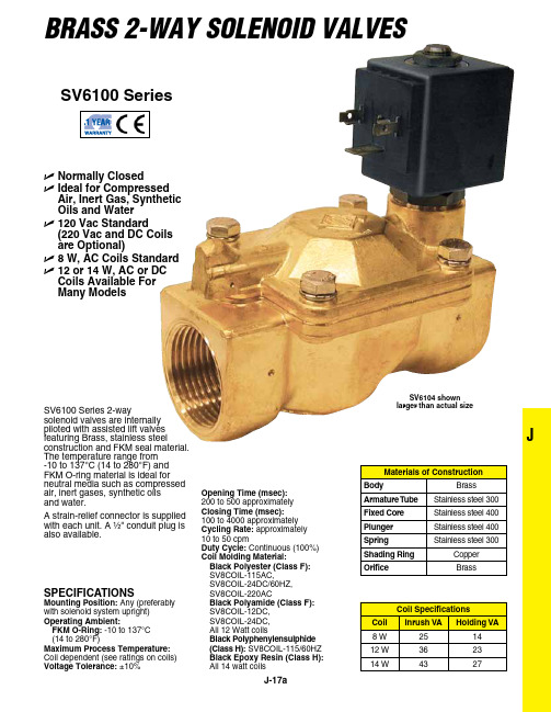
JBRASS 2-WAy Solenoid VAlVeSU N ormally Closed U I deal for Compressed Air, Inert Gas, Synthetic Oils and Water U 120 Vac Standard(220 Vac and DC Coils are Optional)U 8 W, AC Coils Standard U 12 or 14 W, AC or DC Coils Available For Many ModelsSV6100 Series 2-waysolenoid valves are internally piloted with assisted lift valves featuring Brass, stainless steelconstruction and FKM seal material. The temperature range from -10 to 137°C (14 to 280°F) and FKM O-ring material is ideal for neutral media such as compressed air, inert gases, synthetic oils and water.A strain-relief connector is supplied with each unit. A ¹⁄₂" conduit plug is also available.SPECIFICATIONSMounting Position: Any (preferably with solenoid system upright)Operating Ambient:FKM O-Ring: -10 to 137°C (14 to 280°F)Maximum Process Temperature: Coil dependent (see ratings on coils)Voltage Tolerance: ±10%SV6100 SeriesSV6104 shownlarger than actual sizeOpening Time (msec): 200 to 500 approximately Closing Time (msec): 100 to 4000 approximately Cycling Rate: approximately 10 to 50 cpmDuty Cycle: Continuous (100%)Coil Molding Material:Black Polyester (Class F): V8COIL-115AC,V8COIL-24DC/60HZ, V8COIL-220ACBlack Polyamide (Class F): V8COIL-12DC, V8COIL-24DC, All 12 Watt coilsBlack Polyphenylensulphide (Class H): SV8COIL-115/60HZ Black Epoxy Resin (Class H):All 14 watt coilsSV6004/SV6008SV8COIL-12DC, 8W coil for 12 Vdc 154°C (310°F) (Class F).Comes complete with operator’s manual, 8 W coil and cable grip connector.Ordering Examples: SV6105, 1 NPT normally closed valve for 1" orifice.SV6104, 3⁄4" normally closed valve for 3⁄4" orifice.ACBF EDBoth models shown smaller than actual size.SV-CGC, cable grip connector.1⁄2" conduit connector.。
电磁阀说明书

电磁阀说明书电磁阀说明书1. 简介电磁阀是一种常见的控制装置,通过电磁力作用来控制介质(例如液体、气体或气体)的流动。
电磁阀广泛应用于各种工业领域,例如液压系统、气动系统、冷却系统等。
本说明书旨在介绍电磁阀的工作原理、结构、安装和使用方法。
2. 工作原理电磁阀是由电磁线圈和阀体组成的。
电磁线圈通过通电产生磁场,使阀体内的阀芯移动,从而开启或关闭阀门。
在通电或断电状态下,电磁阀起到控制介质流动的作用。
当线圈通电时,磁场吸引阀芯,使阀门打开;当线圈断电时,阀芯弹簧恢复原位,阀门关闭。
3. 结构电磁阀主要由以下几个部分组成:- 阀体:包含阀门和管道接口,用于控制介质的流动。
- 阀芯:位于阀体内,受到电磁力控制,用于打开或关闭阀门。
- 电磁线圈:位于阀体外侧,通过通电产生磁场,控制阀芯的移动。
- 弹簧:用于恢复阀芯原位,关闭阀门。
- 密封件:防止介质泄漏,保证阀门的密封性能。
4. 安装方法在安装电磁阀时,需要注意以下几点:1. 选择合适的阀门类型和规格,根据实际需要确定。
2. 确保安装位置符合要求,避免电磁阀受到外力干扰或介质堵塞。
3. 注意阀门的进出口方向,确保介质能够顺利流动。
4. 连接接口要牢固可靠,确保不会发生泄漏。
5. 注意接线的正确性,防止电磁阀工作异常。
5. 使用方法电磁阀使用时需要注意以下几点:1. 确保电源的正常供应,电压和频率要与电磁阀的标定值相匹配。
2. 操作开关或控制装置,控制电磁阀的通电和断电。
3. 注意使用环境温度,避免过高或过低的温度对电磁阀的影响。
4. 定期检查电磁阀的工作状态,确保正常运行。
5. 当电磁阀长时间不使用时,应断开电源,并进行必要的维护。
6. 注意事项在使用电磁阀时,需要特别注意以下事项:1. 严禁在电磁阀上进行改装或修理,以免造成故障或危险。
2. 禁止超负荷使用电磁阀,确保电磁阀在额定压力和温度下正常工作。
3. 当电磁阀出现异常情况(如漏电、发热等)时,应立即停止使用,并寻求专业人士的帮助。
2w电磁阀说明书
说明书制作要求: 一、 二、 3、
企业商标、网址全数都一致;
大体魄式不变,具体小细节怎么美观怎么做;
提供的样本由于转化过来部份线找不到,制作的时候要补齐。
篇三:电磁阀的利用说明
电磁阀的利用说明
选型要领:
电磁阀选型第一应该依次遵循平安性,靠得住性,适用性,经济性四大原那么,第二是依照六个方面的现场工况(即管道参数、流体参数、压力参数、电气参数、动作方式、特殊要求进行选择)。
设计紧凑,精致美观温升低,无噪音,零泄漏 动作响应迅速,高频率 德国工艺,出口系列,品质靠得住 常开阀高度=H2+20mm
介质含有杂质、阀前必需安装过滤器(滤网≥8ห้องสมุดไป่ตู้目);且无凝固或晶表现象。 型号表示:BZCA-1K,B:防爆;-1≤90℃;-K:常开。 2W电磁阀产品用途
应用于医疗机械、太阳能、清洗设备、食物机械、燃烧器、焊接切割、消防平安、环保水处置、机械制造等行业。
二、当管内流体有倒流现象时,可选择带止回功能电磁阀。
3、当需要对电磁阀进行现场人工操作时,可选择带手动功能电磁阀。
4、露天安装或粉尘多场合应选用防水,防尘品种(防护品级在IP54以上)。
五、用于喷泉必需采纳潜水型电磁阀(防护品级在IP68以上)。
原理概述NJ
追朔电磁阀的进展史,到目前为止,国内外的电磁阀从原理上分为三大类(即:直动式、分步直动式、先导式),而从阀瓣结构和材料上的不同与原理上的区别又分为六个分支小类(直动膜片结构、分步膜片结构、先导式膜片结构、直动活塞结构、分步活塞结构、先导活塞结构) 。3ir^
2w电磁阀说明书
篇一:2W电磁阀
名称:2W电磁阀 型号:2W电磁阀
产品压力:Class150~600Lb 公称通径:DN 15~600mm 产品类别:电磁阀
电磁阀使用说明书

电磁阀使用说明书使用说明书一、产品介绍电磁阀是一种常用的自动控制元件,广泛应用于工业、农业、冶金、电力等领域。
本使用说明书旨在帮助用户正确使用电磁阀,确保其正常运行及延长使用寿命。
二、技术参数1. 工作电压:一般为220VAC,也可根据需要定制其他电压。
2. 工作压力:常见工作压力为0.1MPa-1.6MPa,也可根据实际需求定制其他工作压力。
3. 工作温度:一般为-10℃至80℃,也可根据使用环境要求定制其他工作温度范围。
三、安装及操作1. 安装前请仔细查看产品外观是否完好,避免安装损坏。
2. 电磁阀安装时应垂直放置,避免倾斜或颠倒安装,以确保正常通电操作。
3. 进口与出口接口请使用合适的密封材料,以防止漏气现象的发生。
4. 连接导线时,请确保电源线与电磁阀的接线端正好对应,并紧固好螺丝。
5. 操作时,请遵循以下步骤:a. 检查电磁阀与相关设备的电源线是否连接正常。
b. 检查电磁阀与相关设备的电源开关是否打开。
c. 通过控制开关或按钮来操作电磁阀开关,确保其正常开闭。
四、维护保养1. 保持电磁阀的清洁,避免污物进入影响正常运行。
2. 定期检查电磁阀的电源线及接线端是否松动,如有松动请及时拧紧。
3. 若发现电磁阀工作异常,请立即停止使用,并联系专业人员进行维修。
五、注意事项1. 请勿私自拆解电磁阀,以免造成损坏或安全事故。
2. 使用过程中请勿随意更改产品的工作电压、工作压力或工作温度范围,以免影响产品性能。
3. 遇到雷暴天气或长时间不使用时,请切断电源并将电磁阀垂直存放。
六、故障排除以下情况可能会导致电磁阀故障,请参考以下步骤进行排查:1. 电磁阀无法开启:a. 检查供电电源是否正常。
b. 检查控制开关或按钮是否正常。
c. 检查电磁阀的接线是否正确连接。
d. 若仍无法解决,请联系售后服务部门。
2. 电磁阀无法关闭:a. 检查供电电源是否正常。
b. 检查控制开关或按钮是否正常。
c. 检查电磁阀的接线是否正确连接。
- 1、下载文档前请自行甄别文档内容的完整性,平台不提供额外的编辑、内容补充、找答案等附加服务。
- 2、"仅部分预览"的文档,不可在线预览部分如存在完整性等问题,可反馈申请退款(可完整预览的文档不适用该条件!)。
- 3、如文档侵犯您的权益,请联系客服反馈,我们会尽快为您处理(人工客服工作时间:9:00-18:30)。
Operating Instructions
Wiring Diagram Electrical Connection Type 2509
Ground (green dot)
Power*
Power*
* Orientation is noቤተ መጻሕፍቲ ባይዱ important
Electrical Connection: Ensure supply voltage/frequency corresponds with that on label. Voltage tolerance is ± 10 %. Available Electrical Connections see “Marking”. Wiring diagram see above.
Seal Materials and Fluids handled: See Table 1.
Fluid and Ambient Temperature:
For Hazardous Locations Div. 1 (T4 rated)
Max. Ambient Temperature
104 °F (40 °C)
or General Purpose valve for Hazardous Locations Class I, Division 1, Group A, B, C, D Class II, Division 1, Group E, F, G Class III, Division 1 and 2 Operating Temperature T 6
The maximum torque for the terminal screw on type 2509 is 0,5 Nm (4,4 lbf-in.).
Division 1 Hazardous Locations (T6 rated)
Max. Ambient Temperature
140 °F (60 °C)
Max. Fluid Temperature
140 °F (60 °C)
For Hazardous Locations Div. 2 and Ordinary Locations: See Table 1.
Max. Fluid Temperature
194 °F (90 °C)
The UL-listed valve for Hazardous Locations is suitable for the
fluids air, inert gas, water and gasoline.
Marking (example):
Operating Instructions
Type 6014
Design: 3-way solenoid valve, direct acting, normally closed (Circuit function C), normally open (Circuit function D) or universal function (Circuit function T).
For valves to be used in Intrinsically Safe Applications the positive pole is identified by a “+” on the pin or wire No. 1 has to be connected to the “+”. See Control Drawing for the Rules of Interconnection.
or Intrinsically Safe Apparatus for Hazardous Locations Class I, Division 1, Group A, B, C, D Class II, Division 1, Group E, F, G Class III, Division 1 Operating Temperature T 6
or FM approved as Nonincendive for Hazardous Locations Class I, Division 2, Group A, B, C, D Class II, Division 2, Group F, G Class III, Division 1 and 2 Operating Temperature T 4 UL listed for General Purpose CSA approved for General Purpose
FKM
+ 14 to + 266 + 14 to + 130 + 32 to + 212 + 32 to +130 + 14 to + 266 + 14 to + 130 + 14 to + 266 + 14 to + 130
Operating Instructions 0512/08_EN-EN_00893619
See label on the valve.
Table 1 Fluid Air Water Neutral gas Light oil
Temperatures [°F]
Fluid Temp. Ambient Fluid Temp. Ambient Fluid Temp. Ambient Fluid Temp. Ambient
Seal Materials Buna “N” NBR + 14 to + 194 + 14 to + 130 + 32 to + 194 + 32 to + 130 + 14 to + 194 + 14 to + 130 + 14 to + 194 + 14 to + 130
Seat / O-ring Ethylene Propylene (EPDM) - 40 to + 266 + 14 to + 130 + 32 to + 212 + 32 to + 130 - 40 to + 266 + 14 to + 130
Maximum Pressure
Approvals The valve is either approved as
General Purpose valve for Hazardous Locations Class I, Division 1, Group A, B, C, D Class II, Division 1, Group E, F, G Class III, Division 1 and 2 Operating Temperature T 4
Body Material
BR =
Brass
SS =
Stainless Steel
Seal Material
EPDM =
EPDM
NBR =
NBR
FKM =
FKM
Circuit function
C = Normally Closed
D = Normally Open
T = Universal Function
For this product to be considered UL-listed and CSA approved for General Purpose and FM approved for Hazardous Locations Division 2, it must be in conjunction with either the type 2509 or the type H cable plug connector (Electrically Operated Valves Parts, YSYI2). The connector and gasket must be assembled to the valve with the screw provided after the connection of the wire leads. This valve and connector assembly is delivered together and is to be used as one unit.
PTFE tape is recommended for sealing ports. Mounting is accomplished by means of four M4 x 8 mm tapped holes located on the valve underside. Letters on valve body indicate pressure port, exhaust and outlet of the valve.
Warning: These products are designed to operate in a wide variety of applications, it is the user’s responsibility to select a model that is appropriate for the application. This product is designed to be installed only by suitably qualified and trained personnel. Specifications should not be exceeded under any circumstances.
Pressure Range: Maximum inlet pressure see label on valve.