SMC电磁阀型号说明书
SMC比例阀中文说明书
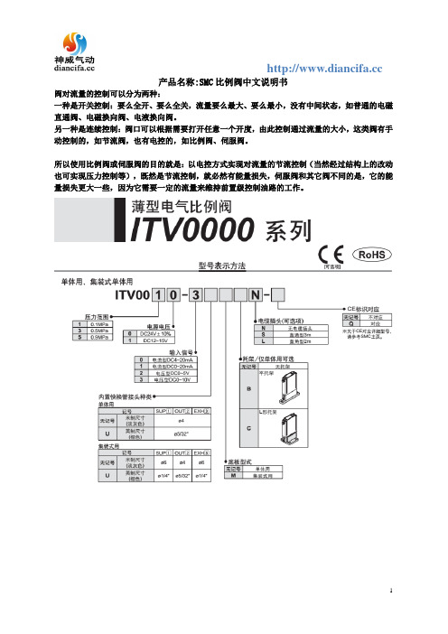
产品名称:SMC比例阀中文说明书
阀对流量的控制可以分为两种:
一种是开关控制:要么全开、要么全关,流量要么最大、要么最小,没有中间状态,如普通的电磁直通阀、电磁换向阀、电液换向阀。
另一种是连续控制:阀口可以根据需要打开任意一个开度,由此控制通过流量的大小,这类阀有手动控制的,如节流阀,也有电控的,如比例阀、伺服阀。
所以使用比例阀或伺服阀的目的就是:以电控方式实现对流量的节流控制(当然经过结构上的改动也可实现压力控制等),既然是节流控制,就必然有能量损失,伺服阀和其它阀不同的是,它的能量损失更大一些,因为它需要一定的流量来维持前置级控制油路的工作。
SMC VX2 直动式2通电磁阀 中文说明书

- ● ●●- --
0.6
1.5
1.2 0.45 0.33
3
0.2 0.35
2.3 0.46 0.61
0.9
0.15 0.35
4.1 0.30 1.10
0.08 0.2
6.4 0.30 1.60
0.03 0.07
8.8 0.30 2.00
1.5
1.2 0.45 0.33
3
0.35 0.9
2.3 0.46 0.61
0.15 0.35
空气
无泄漏、真空注)
电磁阀可选项记号
环境温度℃
NBR、FKM 1cm3 /min 以下 10-6Pa.m3 /sec 以下
无记,G
V,M
注) 可选项记号 V、M 为无泄漏、真空时的值。
mmoorree::nn 注) -10 ~60
注)
-10 ~60
密封材质 NBR FKM NBR EPDM
FKM
PTFE FKM EPDM EPDM PTFE
阀体/短路环材质注6) C37/— SUS/— C37/— SUS/— C37/Cu SUS/Ag C37/Cu SUS/Ag C37/Cu SUS/Ag C37/Cu SUS/Ag C37/Cu SUS/Ag SUS/Ag
密封材质 NBR FKM
NBR
阀体/短路环材质注6) 线圈绝缘种类注
备注
Al/—
B
AC规格请选用全波整流器内藏型
Al/—
B
AC规格请选用全波整流器内藏型
C37/Cu
B
SUS/Ag
温水
E P
无记号
EPDM
C37/Cu SUS/Ag
H
smc电磁阀选型样本
SMC电磁阀选型样本引言电磁阀作为自动化控制系统中常用的执行元件,广泛应用于工业生产中。
SMC 公司是世界上知名的气动控制和自动化设备制造商。
本文将介绍SMC电磁阀的选型要点,并给出一个选型样本。
选型要点在选择SMC电磁阀时,需要考虑以下几个要点:1. 工作压力工作压力是选型电磁阀的重要参数之一。
根据实际应用需要,选择适当的工作压力范围。
SMC电磁阀的工作压力通常在0.15MPa至1.0MPa之间。
2. 电压类型SMC电磁阀有直流和交流两种电压类型可选。
根据实际输入电压类型选择合适的电磁阀。
常见的电压类型有DC24V、AC110V和AC220V等。
3. 连接口径连接口径取决于系统的气源管道大小。
常见的连接口径有M5、G1/8、G1/4和G3/8等。
根据气源管道的尺寸选择合适的连接口径。
4. 工作模式根据实际工作需求,选择合适的工作模式。
SMC电磁阀常见的工作模式包括常闭型(通电时阀门关闭)和常开型(通电时阀门打开)。
5. 阀门类型SMC电磁阀有多种不同类型的阀门,包括直动式和间接式。
根据实际需求选择适合的阀门类型。
选型样本基于上述选型要点,以下是一个选型样本:标题:SMC电磁阀选型样本应用场景该选型样本适用于一个工业生产线上的气动控制系统,需要使用电磁阀控制气体流动。
选型要点•工作压力范围:0.15MPa至1.0MPa•电压类型:DC24V•连接口径:G1/4•工作模式:常开型•阀门类型:直动式选型结果基于以上要点,推荐选择以下型号的SMC电磁阀:型号:NVJ114-5G40B主要参数•工作压力范围:0.15MPa至1.0MPa•电压类型:DC24V•连接口径:G1/4•工作模式:常开型•阀门类型:直动式特点和优势•结构紧凑,体积小,重量轻•高性能密封材料,工作可靠•适用于空气、水和其他非腐蚀性介质的控制结论根据应用场景和选型要点,推荐选择SMC型号NVJ114-5G40B直动式常开型电磁阀,该电磁阀具有良好的工作压力范围、适合的接口尺寸和工作电压,并且具有紧凑的结构和高性能密封材料,能够满足工业生产线上的气动控制需求。
SMC ZSE40A(F) ISE40A数字压力开关操作手册说明书

Digital Pressure SwitchOperation ManualZSE40A(F)/ISE40AThank you for purchasing the SMC ZSE40A(F)/ISE40A Series Digital Pressure Switch.Please read this manual carefully before operating the digital pressure switch and make sure you understand the digital pressure switch, its capabilities and limitations.Please keep this manual handy for future reference.To get information in detail for operating this product, refer to SMC website (URL ) or contact us.Indication light (Orange LED): Displays the switch operation condition.LCD display: Displays the current status of pressure, setting mode and error code.Four display modes can be selected to display always in red orgreen only, or changing from green to red, red to green according to the output status.button (UP): Selects the mode or increases the ON/OFF set value.Press this button to change to the peak display mode.button (DOWN): Selects the mode or decreases the ON/OFF set value.Press this button to change to the bottom display mode.button (SET): Press this button to change to either mode and to set a value.These safety instructions are intended to prevent hazardous situations and/or equipment damage.These instructions indicate the level of potential hazard with the labels of"Caution", " Warning" or "Danger". They are all important notes for safety and must be followed in addition to International standards (ISO/IEC), Japan Industrial Standards (JIS) and other safety regulations.OperatorInstallationMountingMount the optional bracket and panel mount adapter to the pressure switch.When the pressure switch is to be mounted in a place where water and dust splashes occur, insert a tube into the air-relieving port of the pressure switch.(Refer to "Tube attachment")Mounting with bracketFix the bracket to the pressure switch with the set screws M3x5L (2 pcs.) or M4x5L (2 pcs.) supplied.Apply a tightening torque of 0.5 to 0.7 Nm for the M3 set screws or 1.4 to 1.6 Nm for the M4 set screws .WiringConnection Make connection after turning the power e a separate route when connecting the wire ofthe Pressure switch.Malfunction stemming from noise may occur if the wire is installed in the same route as that of power or high-voltage cable.Be sure to ground terminal FG when using a commerically available switch-mode power supply.When the switch-mode power supply is connected to the Pressure switch,switching noise wil be superimposed and product specification can no longer be met. This can be prevented by inserting a noise filter, such as a line noise filter and ferrite core, between the switch-mode power supply and the Pressure switch, or by using a series power supply instead of the switch-mode power supply.Names of individual partsSet ON point and OFF point of the Pressure switch.Operation When the pressure exceeds a set value, the Pressure switch will be turned on.When the pressure falls below the set value by the amount of hysteresis or more, the Pressure switch will be turned off.The default setting of the output set value is the central value between the atmospheric pressure and the upper limit of the rated pressure range. If theoperation shown the right does not cause any problem, keep this operation setting.Switch ONP_1H_1Time [s]P r e s s u r e [P a ]<How to operate>button once in measurement mode.(2)[P_1] or [n_1] and set value are displayed in turn.Normal output Reversed outputbutton once to increase by one figure, and press it continuously to keep button once to decrease by one button to finish the setting of OUT1.[ Window comparator mode ]The Pressure switch turns on within a set pressure range (from P1L to P1H)during window comparator mode. Set P1L (switch lower limit) and P1H (switch At the time of shipment, the following settings are provided.If the setting is acceptable, keep it for use.To change setting, refer to SMC website (URL ) to get information in detail or contact us.[F 0] Unit conversion functionSame setting as [F 1] OUT1.At the output mode, Error detection mode can be selected.Display color is linked to the setting of OUT1, and can not be selected.Other parameter settingMeasurement modeThe measurement mode is the condition where the pressure is detected and indicated, and the switch function is operating.This is the basic mode, and other modes should be selected for setting change and other function setting changes.Function selection modeMeasurement modePeak/Bottom hold value indication Zero clear Key lockTo set each function the above in detail, refer to SMC website (URL ) to get information in detail or contact us.MaintenanceHow to reset the product after power cut or forcible de-energizing The setting of the product will be retained as it was before a power cut or de-energizing.The output condition is also basically recovered to that before a power cut or de-energizing, but may change depending on the operating environment.Therefore, check the safety of the whole facility before operating the product. If the facility is using accurate control, wait until the pressure switch has warmed up.(About 10 to 15 minutes)∗:Some functions are not available depending on part number. All functions are displayed with[F ] and followed with function description. If a function is not available for specified type, the function is displayed as [---].TroubleshootingError indication functionThis function is to display error location and content when a problem or an error occurs.SpecificationRefer to the product catalogue or SMC website (URL ) to get information about product specifications in detail.Outline with Dimensions (in mm)Refer to the product catalogue or SMC website (URL ) to get information about outline dimensions in detail.Akihabara UDX 15F, 4-14-1, Sotokanda, Chiyoda-ku, Tokyo 101-0021, JAPAN Phone: +81 3-5207-8249 Fax: +81 3-5298-5362URL Note: Specifications are subject to change without prior notice and any obligation on the part of the manufacturer.© 2009 SMC Corporation All Rights Reserved•Bracket A or D(Model: ZS-24-A/ZS-24-D)•Bracket B (Model: ZS-24-B)[01/N01 type][W1/WF1 type]button for 2[F 0]. Select to display the function setting to be changed, [F ].button for 2selection mode to return tomeasurement mode.。
smc电磁阀选型样本

SMC电磁阀选型样本1. 引言SMC电磁阀是一种常用的控制元件,在自动化控制系统中起着非常重要的作用。
选型合适的SMC电磁阀能够有效控制液体、气体等流体的流动,并实现系统的自动控制。
本文档将介绍SMC电磁阀的选型原则、货号解析以及常用型号的参数和特点,帮助用户更好地选择合适的SMC电磁阀,确保系统的正常运行。
2. SMC电磁阀选型原则在选择SMC电磁阀时,需要考虑以下几个因素:2.1 流量要求根据实际应用需求确定所需要的流量范围。
电磁阀的通径越大,其能够处理的流量就越大。
因此,在选型时,需要参考所需的流量和系统的耗气量,选择合适的通径和口径。
2.2 工作压力电磁阀的工作压力需要根据系统的工作压力来确定。
一般情况下,选型时需要考虑系统的最高工作压力,并留有一定的余量,以确保电磁阀能够正常工作。
2.3 工作介质电磁阀的工作介质通常包括气体和液体。
在选型时,需要注意工作介质的种类、温度、粘度等因素,以保证电磁阀对工作介质的适应性和稳定性。
2.4 工作环境工作环境也是选型的重要因素之一,包括温度、湿度、腐蚀性气体等。
电磁阀的选型需要考虑工作环境的特点,选择适合的外壳材料和密封材料,以保证电磁阀在恶劣环境下的可靠性和稳定性。
3. SMC电磁阀货号解析SMC电磁阀的货号通常由一系列数字和字母组成,每个字符代表了不同的信息。
以下是SMC电磁阀货号的解析方法:•第一个字符:代表产品系列。
例如,“SY”代表“多通电磁阀系列”,“SV”代表“低功率电磁阀系列”等。
•第二个字符:代表产品类型。
例如,“A”代表“四通电磁阀”,“B”代表“三通电磁阀”等。
•第三个字符:代表电磁阀的口径。
例如,“025”代表“2.5mm”,“200”代表“20mm”等。
•第四个字符:代表任务位置。
例如,“R”代表“正常耐压”,“L”代表“低耐压”等。
•其余字符:代表特殊功能或选项。
例如,“10”代表“AC220V”,“30”代表“DC24V”等。
SMC比例阀中文说明书

ITV1000-※1 ITV2000-※1 ITV3000-※1(模拟输出/电压型)使用说明书值此,谨对您选购SMC 公司的产品表示诚挚的谢意。
请仔细阅读本使用说明书,相信必将有助于您正确使用本产品。
为以防万一,请您一定好好保管此说明书。
安全注意事项这里所描述到的,是提请您正确安全的使用本产品,以防止对您自身和他人造成危害和损害的各种注意事项。
请结合ISO 4414, JIS B 8370以及其他的相关安全规则,务必遵守。
注意关于配管1.请将配管用空气吹净或清洗干净,以除去配管内的切屑,切削油及杂质等。
2.将配管和管接头拧紧时,请注意勿将配管的螺纹切屑及密封材混入配管中。
另需强调,使用密封胶带包卷管接头螺纹时,请在螺纹先端留出1.5~2个螺距的空间。
注意关于压缩气源1. 在靠近本产品的供气侧,请选择安装过滤精度在5μm 以下的空气过滤器。
2. 压缩空气若含有大量的水分,将导致本产品及其他的气动元件作动不良。
请实施相应对策,诸如设置后冷却器,空气干燥器,水分分离器等。
3. 在本产品内部大量附着由空气压缩机所产生的碳粉时,将导致其作动不良。
! !各部分名称外形尺寸配线电缆接线端子安装托架外形尺寸安装孔安装孔UP 键(△键) 设定键(SET 键) DOWN 键(▽键)显示用LEDSUP 接口OUT 接口压力表用接口安装托架(选配)右弯出线型电缆接线端子 (4芯)(选配)安装托架(选配)右弯出线型电缆接线端子直线出线型电缆接线端子 (4芯)(4芯)安装孔安装孔注1) 输出压力0.1MPa规格最大供给压力为0.2MPa。
注2) 超出规格范围时,会发生破损,请注意。
■ 配线方法电缆与本体的端子连接时,请以下记的形式进行配线。
注意因可能发生由于误配线而导致破损的情况,请使用时注意。
请使用容量足够大,脉动小的直流电源。
1 茶 供给电源2 白 输入信号3 青 GND (COMMON)4 黑显示输出注)电缆也有右弯出线型的。
SMC VXD21 22 23 系列 先导式 2 通电磁阀 说明书

先导式2通电磁阀 V X D 21/22/23系列使用说明书A 伴随规格追加新作成 ‘06.8.19 茅根 符号处数变更事项年月日担当者登录NO.VXDN***-OMJ0001-A SMC 株式会社目录1.目录 —————————————————————————- P12.安全上的注意事项———————————————————— P33.流量特性 ——————————————————————— P94.规格 —————————————————————————- P185.型号表示———————————————————————— P226.故障与对策——————————————————————— P28VXD21/22/23系列单体阀体尺寸接管口径(法兰)2通电磁阀这里所指的注意事项记载了产品应如何安全正确的使用,以防止对人身或设备造成损伤。
根据其潜在的危险程度,将有关注意事项分成「注意」、「警告」、「危险」三种标志。
有关安全方面的重要内容,都记载在ISO 4414※1)JIS B 83702)※以及其他安全规则中,必须遵守。
1) ISO4414※:pneumatic fluid power—General rules relating to systems。
2)JIS B 8370※:气动系统通则。
警告请系统的设计者或决定规格的人员来判断元件的选型是否合适。
产品样本上登载的产品,由于其使用条件多种多样,应由系统的设计者或决定规格的人来决定所选元件是否适合该系统。
必要时,还应做相应的分析和试验。
满足系统所期望的性能并保证安全是决定系统适合性的人的责任。
还应依据最新产品样本和资料,检查规格的全部内容,并考虑到元件可能会出现的故障情况,最终组成该系统。
在决定使用流体的合适性时要特别注意。
②请具备充分知识和经验的人使用设备。
流体及安装错误是有一定危险的。
使用元件的机械装置在组装、操作和维护等时应由有充分知识和经验的人进行。
SMC系列产品使用说明书
5.4 SMC/HBC、SMC/JA部分回转产品的安装与拆卸方法是:
先将花键接头装到阀杆上,使电动装置二级减速机构的驱动轴位置与阀门所处位置相同。
(此时阀门在某一终端位置最理想)起吊电动装置,使其驱动轴与阀杆上的花键接头对准,同时应对准阀门与电动装置的连接螺孔。使驱动轴与花键接头配合装入,而后用螺栓将阀门与电动装置紧固可靠。
a、型号:该产品型号。
b、最大控制转矩:该产品出厂前调定的最大转矩值(N.m)。
c、输出转速:该产品在单位时间内输出轴的转圈数(r/min)。
d、最大转圈数:该产品位置指示机构指针从0~100%走满刻度情况下输出轴总的转圈数。
e、编号:该产品总序号或本年度产品的序号。
f、合同号:该产品年度订货合同号。根据它可查出产品出厂前的全部情况,便于售后服务。
与G·L·SW的触点信号不同,MDPI的阀位反馈信号是连续的。
(图19)所示为MDPI位置指示机构的结构。从图中可见其传动部分是若干对小模数配换齿轮,该机构对任何口径的阀门均能保证其指针做满刻度指示。
▼关于电动装置的控制器
对于一般控制原理,控制器是与电动装置分离的电气控制部件,它通常设置在控制室内为单独订货产品。
5.7电动装置的工作位置一般无原则要求。但推荐电动机轴线为水平状态,G·L·SW箱罩处于水平或垂直向上、向下状态,以利于产品的润滑、维修及阀位观测。
6.润滑
6.1产品出厂前已注入专用润滑脂,使用中每年应至少检查润滑情况一次,如无异常可继续使用。
6.2电动机轴承的润滑脂一般不必更换或添加。
6.3产品维修后更换润滑脂时应注意其抗氧化性、耐水性、耐热性、防锈性、机械稳定性等,并应注意其抗挤压性,以保证产品的润滑性能和较高的传动效率。