研控步进电机说明书
步进电机说明书

17HS001
17HS101
- +55 !" !" 500V DC 100M 0.1 0.3mm 0.02mm Max 85 Max B
17HS111
! "10-85% ! !"#$"% Min ! "
!" -25
!" !" !" !"
!"#
电机型号 17HS001 原型号42BYGH001 17HS101 原型号42BYGH101 17HS111
Start MicroStep Co., Ltd.
!"#$%&'()*+
5
! " # $ SERIES STEP MOTORS
110BYG250A
!" -25
110BYG250B
110BYG250C
! "
!" !" !" !"
- +55 !" !" 500V DC 100M 0.1 0.3mm 0.02mm Max 85 Max B
!"#$ /
相数 步距角 相电流 驱动电压 最大静转矩 相电阻 0.15Nm 2 1.8° 1.7A DC24V 0.35Nm 0.45Nm
!" !"
相电感
转动惯量
重量
空载启动 转速 390转/分
配套驱动器
1.4Ω 2.3Ω 3.3Ω
SH-2H042Ma SH-2H042Mb 2.88mH 0.032kg·cm 0.24kg 396转/分 MS-2H057M
Start MicroStep Co., Ltd.
步进电机产品说明书

FixedSeries LEPY/LEPSSpecific Product Precautions 1Be sure to read before handling. Refer to back cover for Safety Instructions and the Operation Manual for Electric Actuator Precautions. Please download it via our website, 20C o u r t e s y o f C M A /F l o d y n e /H y d r a d y n e ŀ M o t i o n C o n t r o l ŀ H y d r a u l i c ŀ P n e u m a t i c ŀ E l e c t r i c a l ŀ M e c h a n i c a l ŀ (800) 426-5480 ŀ w w w .c m a f h .c o m7.When it is necessary to operate the product by the manual override screw, check the position of the manual override and leave necessary space for access.Do not apply excessive torque to the manual override screw. This may lead to damage and malfunction.8.When an external guide is used, connect it in such a way that no impact or load is applied to it.This may cause a malfunction due to an increase in sliding resistance, or use a freely moving connector (such as a floating joint).1.When the pushing operation is used, be sure to set to [Pushing operation].Also, do not hit the workpiece in positioning operation or in the range of positioning operation.I t may damage and malfunction. If the operation is interrupted or stopped during the cycle: W hen the pushing operation command is output immediately after restarting the operation, the direction of movement depends on the position of restart.e the product within the specified pushing speed range for the pushing operation.It may lead to damage and malfunction.3.For the pushing operation, ensure that the force is applied in the direction of the rod axis.4.The moving force should be the initial value.If the moving force is set below the initial value, it may cause an alarm.5.The actual speed of this actuator is affected by the load.Check the model selection section of the catalog.6.Do not scratch or dent the sliding parts of the rod, by striking or attaching objects.The rod is manufactured to precise tolerances, even a slight deformation may cause malfunction.7.Avoid using the electric actuator in such a way that rotational torque would be applied to the rod.It may cause deformation of the non-rotating sliding part, leading to clearance in the internal guide or an increase in the sliding resistance.Refer to the table below for the approximate values of the allowable range of rotational torque.HandlingCautionMountingWarningSide mounting (Body mounting through-hole)Side mounting (Body tapped)Bottom mounting (Body tapped)Rod side mounting (Rod type only)6.Tighten the mounting screws within the specified torque range.Tightening with higher torque than the specified range may cause malfunction while the tightening with lower torque can cause the displacement of gripping position or dropping a workpiece.Series LEPY/LEPSSpecific Product Precautions 2Be sure to read before handling. Refer to back cover for Safety Instructions and the Operation Manual for Electric Actuator Precautions. Please download it via our website, 21C o u r t e s y o f C M A /F l o d y n e /H y d r a d y n e ŀ M o t i o n C o n t r o l ŀ H y d r a u l i c ŀ P n e u m a t i c ŀ E l e c t r i c a l ŀ M e c h a n i c a l ŀ (800) 426-5480 ŀ w w w .c m a f h .c o mHandlingCaution13.In pushing operation, set the product to a position of atleast 0.5 mm away from a workpiece. (T his position is referred to as a pushing start position.)The following alarms may be generated and operation may become unstable.a. “Posn failed” alarm is generated.The product cannot reach a pushing start position due to variation in the width of workpieces.b. “Pushing ALM” alarm is generated.The product is pushed back from a pushing start position after starting to push.c. “Deviation over flow” alarm is generated.Displacement exceeding the specified value is generated at the pushing start position.14.For the pushing operation, use the product within theduty ratio range below.The duty ratio is a ratio at the time that can keep being pushed.15.When mounting the product, keep a 40 mm or longerdiameter for bends in the cable.MaintenanceWarning1.Ensure that the power supply is stopped and the workpiece is removed before starting maintenance work or replacement of the product.8.Do not operate by fixing the rod and moving the actuatorbody.Excessive load will be applied to the rod, leading to damage to the actuator and reduced the life of the product.9.Return to origin1)Do not apply a load, impact or resistance in addition to the transferred load during return to origin.Additional force will cause the displacement of the origin position since it is based on detected motor torque.2)W hen the return to origin is set with <Basic parameter> [Origin offset], it is necessary to change the current position of the product. Recheck the value of step data.3)It is recommended to set the directions of return to origin and pushing in the same direction in order to enhance the measurement accuracy during pushing operation.10.There is no backlash effect in pushing operation.The return to origin is done by the pushing operation.The position can be displaced by the effect of the backlash during the positioning operation.Take the backlash into consideration when setting the position.11.Do not hit the stroke end except during return to origin.This may damage the inner parts.12.INP output signal1) Positioning operationW hen the product comes within the set range by step data [In position], the INP output signal will turn on.Initial value: Set to [0.50] or higher.2)Pushing operationW hen the effective pushing force exceeds the step data [Trigger LV], the INP output signal will turn on.W hen [Pushing force] setting and [Trigger LV] are set less than [Pushing force], use the product within the specified range of[Pushing force] and [Trigger LV].a)To ensure that the actuator pushes the workpiece with the set [Pushing force], it is recommended that the [Trigger LV]be set to the same value as the [Pushing force].b)If the [Trigger LV] is set lower than the [operation pushing force (current pushing force) for the pushing operation], the pushing force will exceed the trigger LV from the pushing start position and the INP output signal will turn on before pushing the workpiece. Increase the pushing force, or change the work load so that the current pushing force becomes smaller than the trigger LV.Series LEPY/LEPSSpecific Product Precautions 3Be sure to read before handling. Refer to back cover for Safety Instructions and the Operation Manual for Electric Actuator Precautions. Please download it via our website, 22C o u r t e s y o f C M A /F l o d y n e /H y d r a d y n e ŀ M o t i o n C o n t r o l ŀ H y d r a u l i c ŀ P n e u m a t i c ŀ E l e c t r i c a l ŀ M e c h a n i c a l ŀ (800) 426-5480 ŀ w w w .c m a f h .c o m。
研控步进电机YKA2811S说明书

高性能两相混合式步进电机驱动器
指示灯和电位器功能说明
标记符号
功能
注
释
PWR 电源指示灯
驱动器通电时,绿色指示灯亮。
TM 零点指示灯
零点信号有效,有脉冲连续输入时,绿色指示灯点亮。
O.H 过热指示灯
过热时,红色指示灯点亮。
O.C 过流/电压过低指示灯
电流过高或者电压过低时,红色指示灯亮。
Im 电机线圈电流设定电位器 调整电机相电流,逆时针减小,顺时针增大。
FL~AC
高性能两相混合式步进电机驱动器
隔离正端
有效(低电平),温度降至 50 度时驱动器自动恢复工作并清除
过热/电压过低保护保护光电 FL 信号 FL+接输出信号限流电阻,FL-接输出地;最大输出电流
隔离负端
50mA,最高电压 50V。
电源
AC60V~130V
+A、-A 电机接线
+B、-B
!注意:
DR+ 输入信号光电隔离正端
接+5V 供电电源+5V-+24V 均可驱动,高于+5V 需接限流电阻,请 参见第 6 页输入信号。
DR-
DP1=OFF 时为方向控制信号 用于改变电机转向。输入电阻 220Ω ,要 求 :低 电平 0-0.5V, DP1=ON 时为反向步进脉冲信号 高电平 4-5V,脉冲宽度>2.5us。
DIP 开关功能设定
高性能两相混合式步进电机驱动器
OFF:脉冲信号+方向信号控制方式(PU 为脉冲信号,DR 为方向信号)
DP1
ON: 正向脉冲+反向脉冲控制方式(PU 为正向脉冲,DR 为反向脉冲)
OFF:整步运行方式
步进电机控制器说明书
步进电机控制器说明书步进电机控制器说明书一、产品概述本文档旨在提供有关步进电机控制器的详细说明。
步进电机控制器是一种用于控制步进电机运动的装置,通过电子方式驱动步进电机实现精确的位置控制。
本控制器具有高精度、可编程性强等特点,适用于各种不同的步进电机应用场景。
二、产品特性本节介绍步进电机控制器的主要特性和功能。
2.1 高精度驱动步进电机控制器采用先进的驱动技术,能够实现高精度的步进电机驱动,可满足精密定位和运动控制需求。
2.2 可编程控制控制器内置丰富的控制算法,支持用户编程,可以根据具体应用需求进行自定义控制,提供更灵活的控制方式。
2.3 多种通信接口本控制器支持多种通信接口,如RS232、RS485、CAN等,便于与其他设备进行通信,实现系统集成和数据传输。
2.4 多种操作模式控制器提供多种操作模式选择,如速度控制、位置控制、力控制等,适应不同应用场景的需求。
2.5 安全保护功能为了确保系统的安全性,本控制器内置了多种安全保护功能,如过流保护、过热保护等,提供有效的保护措施。
三、产品安装和连接本节介绍步进电机控制器的安装和连接方式。
3.1 安装首先,确保电源已经断开。
将控制器固定在合适的位置,通过螺丝固定。
确保控制器和其他设备之间的空间足够,并保持良好的通风。
3.2 连接根据具体应用需求,通过合适的连接线将控制器与步进电机、电源等设备连接。
注意连接的正确性和稳定性,避免接触不良和短路等问题。
四、控制器编程及操作指南本节介绍步进电机控制器的编程和操作方法。
4.1 控制器编程步进电机控制器支持多种编程方式,如C语言、Python等。
用户可以编写相应的代码实现对步进电机的控制和驱动。
4.2 控制器操作指南控制器提供用户友好的操作界面,通过按钮、旋钮等方式进行控制操作。
用户可以根据界面上的指示进行相应的参数设置、模式切换等操作。
五、常见问题与解答本节了一些常见问题,并提供相应的解答。
如果用户遇到其他问题,建议参考本节解答,若问题仍未解决,可联系技术支持人员。
步进电机驱动器使用手册说明书

步进电机驱动器使用手册目录1安全事项 (2)2产品外形 (4)2.1产品外形 (4)3接口定义 (5)3.1电机、电源接口C N1 (5)3.1.1两相步进电机接线 (5)3.1.2五相步进电机接线 (6)3.2控制接口C N2 (7)3.2.1脉冲(P u l)信号/上限位信号 (9)3.2.2方向(D i r)信号/下限位信号 (9)3.2.3回零(Z e r o)信号/原点信号 (9)3.2.4脱机/使能(F r e e/E n a b l e)信号 (9)3.2.5到位(I N P)信号 (10)3.2.6就绪(R D Y)信号 (11)3.2.7接口电压 (11)3.3编码器接口C N3 (13)3.4U S B接口C N4 (14)3.5M o d b u s接口C N5 (15)4L E D指示 (16)4.1状态指示L E D (16)4.2通讯指示L E D (18)5性能参数 (18)5.1机械参数 (18)5.2安装尺寸 (19)6应用指南 (20)6.1安装准备 (20)6.2机械安装 (20)6.3电气安装 (21)6.4日常维护 (21)6.5注意事项 (21)6.5常见问题 (22)为保障使用者人身安全,保护设备正常使用,请务必阅读并遵守本章的安全事项。
在操作时违反本事项所示要求,可能会导致人员重伤或者死亡。
在操作时违反本事项所示要求,可能会引起驱动器永久损坏及附加事故。
谨防触电,爆炸或其他危险禁止在易爆、易燃或腐蚀性环境使用本产品;禁止开启产品外壳;驱动器带电时内部电压可能超过36VDC,驱动器和电机都必须接安全保护地线;驱动器内部电压不会瞬间释放,必须先切断电源,等指示灯熄灭后才能进行插拔、接线、设置、测量、搬动等人工操作;禁止带电插拔;驱动器故障时温度可能很高,必须先切断电源,等下降至安全温度后才能进行人工操作;驱动器应用于直接涉及人身安全的设备,必须配备人身安全防范措施;驱动器或设备故障时可能存在火灾隐患,必须配备消防安全防范措施。
研控步进电机YKB2608MGH说明书
――过热保护 ――过流、电压过低保护 ◆ 体积小巧 YKA2608MG(H)是一款经济、小巧的步进驱动器,体积为45x136x92mm2。
有效(低电平)时关断电机线圈电流,驱动器停止工作,电机 处于自由状态。
+ 原点输出光电隔离正端
电机线圈通电位于原点置为有效(B,-A 通电);光电隔离输出 (高电平)。
+端接输出信号限流电阻,TM 接输出地。最大驱动电流 50mA, TM 原点输出信号光电隔离负端
最高电压 50V。
+V 电源正极 -V 电源负极
O.C 过流/电压过低指m 电机线圈电流设定电位器 调整电机相电流,逆时针减小,顺时针增大。
引脚功能说明
标记符号
功能
注
释
+ 输入信号光电隔离正端
接+5V 供电电源+5V-+24V 均可驱动,高于+5V 需接限流电阻,请 参见第 6 页输入信号。
PU
D2=OFF 时为步进脉冲信号
D2=OFF 时为方向控制信号
用于改变电机转向。输入电阻 220Ω ,要 求 :低 电平 0-0.5V,
D2=ON 时为反向步进脉冲信号 高电平 4-5V,脉冲宽度>2.5us。
+ 输入信号光电隔离正端 MF 电机释放信号
接+5V 供电电源+5V-+24V 均可驱动,高于+5V 需接限流电阻,请 参见第 6 页输入信号。
研控步进电机YKA2811MA说明书

YKA2811MA细分驱动器特点◆ 高性能、低价格、低噪音、平稳性极好◆ 设有32档等角度恒力矩细分◆ 采用独特的控制电路,有效的降低了噪音,增加了转动平稳性◆ 最高反应频率可达200Kpps◆ 步进脉冲停止超过100ms时,线圈电流自动减半,减小了许多场合的电机过热◆ 双极恒流斩波方式,使得相同的电机可以输出更大的速度和功率◆ 光电隔离信号输入/输出◆ 驱动电流从0.5A/相到8.0A/相连续可调◆ 单电源输入,电压范围:AC60-130V◆ 出错保护:――过热保护――过流、电压过低保护典型应用雕刻机中型数控机床包装机抛光设备恒速应用简述YKA2811MA为一款等角度恒力矩细分型驱动器,最高细分数能达到200细分,驱动电压交流60V~130V,适配电流在8A以下、外径86~130mm的各种型号的两相混合式步进电机。
电器规格说明 最小值 典型值 最大值 供电电压(VAC) 60 100 130峰值输出电流(A) 0.5 跟用户要求有关 8.0逻辑输入电流(mA) 15步进脉冲相应频率(KHz)- - 200脉冲低电平时间(uS) 2.5 - -电流设定1. STOP/Im为保持状态输出电流设置电位器,可设置为正常输出电流的20%~80%(顺时针增大,逆时针减小)2. RUN/Im为正常工作输出电流设置开关(详见下表)R-1 0 1 2 3 4 5 6 7 8 9 A B C D E F Im(A) 0.5 1.0 1.5 2.0 2.5 3.0 3.5 4.0 4.5 5.0 5.5 6.0 6.5 7.0 7.58.0细分设定SK 0 1 2 3 4 5 6 7 8 9 A B C D E F 细分数200 100 8064 50 4032252016108 5 4 2 1DIP开关功能设定DP1 OFF:接受外部脉冲ON :驱动器内部自发7.5KHz脉冲DP2 OFF:脉冲信号+方向信号控制方式ON :正向脉冲+反向脉冲控制方式驱动器接线示意图输入信号波形时序图安装尺寸(单位:mm)指示灯和电位器功能说明标记符号 功 能 注 释 PWR 电源指示灯 驱动器通电时,绿色指示灯亮。
研控步进电机YKA2608MCD说明书

驱动器接线示意图
安装尺寸(单位:mm)
高性能两相混合式步进电机驱动器
z 采用侧面安装,散热效果较好
YKA2608MC 细分设定表
细分数 D6 D5 D4 D3
D2
D1
1 2 4 5 8 10 20 25 40 50 100 200 200 200 200 200 ON OFF ON OFF ON OFF ON OFF ON OFF ON OFF ON OFF ON OFF ON ON OFF OFF ON ON OFF OFF ON ON OFF OFF ON ON OFF OFF ON ON ON ON OFF OFF OFF OFF ON ON ON ON OFF OFF OFF OFF ON ON ON ON ON ON ON ON OFF OFF OFF OFF OFF OFF OFF OFF ON,双脉冲:PU 为正向步进脉冲信号,DR 为反向步进脉冲信号 OFF,单脉冲:PU 为步进脉冲信号,DR 为方向控制信号 自检测开关(OFF 时接收外部脉冲,ON 时驱动器内部发 7.5kHz 脉冲)
典型应用
雕刻机
激光打标机
激光内雕机
概述
YKA2608MC(D)是等角度恒力矩细分型高性能步进驱动器,驱动电压DC24-80V,采用单电源供电。适 配6或8出线电流在6.0A以下,外径57-86mm的各种型号的二相混合式步进电机。
该驱动器内部采用双极恒流斩波方式,使电机噪音减小,电机运行更平稳;驱动电源电压的增加使得 电机的高速性能和驱动能力大为提高;而步进脉冲停止超过100ms时,线圈电流自动减半,使驱动器的发 热可减少50%,也使得电机的发热减少。用户在脉冲频率不高的时候使用低速高细分,使步进电机运转精 度提高,最高可达200细分,振动减小,噪声降低。
- 1、下载文档前请自行甄别文档内容的完整性,平台不提供额外的编辑、内容补充、找答案等附加服务。
- 2、"仅部分预览"的文档,不可在线预览部分如存在完整性等问题,可反馈申请退款(可完整预览的文档不适用该条件!)。
- 3、如文档侵犯您的权益,请联系客服反馈,我们会尽快为您处理(人工客服工作时间:9:00-18:30)。
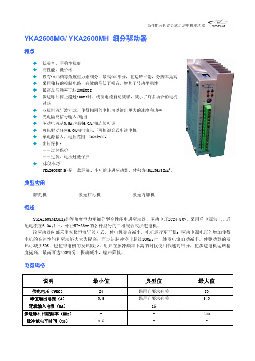
YKA2608MC/ YKA2608MD 细分驱动器
特点
◆ 高性能、低价格
◆ 设有12/8档等角度恒力矩细分,最高200细分,使运转平滑,分辨率提高
◆ 采用独特的控制电路,有效的降低了噪音,增加了转动平稳性
◆ 最高反应频率可达200Kpps
◆ 步进脉冲停止超过100ms时,线圈电流自动减半,减小了许多场合的电机
过热
◆ 双极恒流斩波方式,使得相同的电机可以输出更大的速度和功率
◆ 光电隔离信号输入/输出
◆ 驱动电流从0.0A/相到6.0A/相连续可调
◆ 可以驱动任何6.0A相电流以下两相混合式步进电机
◆ 单电源输入,电压范围:DC24-80V
◆ 出错保护:
――过热保护
――过流、电压过低保护
◆ 体积小巧
YKA2608MC(D)是一款经济、小巧的步进驱动器,体积为45x136x92mm2。
典型应用
雕刻机激光打标机激光内雕机
概述
YKA2608MC(D)是等角度恒力矩细分型高性能步进驱动器,驱动电压DC24-80V,采用单电源供电。
适配6或8出线电流在6.0A以下,外径57-86mm的各种型号的二相混合式步进电机。
该驱动器内部采用双极恒流斩波方式,使电机噪音减小,电机运行更平稳;驱动电源电压的增加使得电机的高速性能和驱动能力大为提高;而步进脉冲停止超过100ms时,线圈电流自动减半,使驱动器的发热可减少50%,也使得电机的发热减少。
用户在脉冲频率不高的时候使用低速高细分,使步进电机运转精度提高,最高可达200细分,振动减小,噪声降低。
电器规格
说明 最小值 典型值 最大值 供电电压(VDC) 24 跟用户要求有关 80
峰值输出电流(A) 0.0 跟用户要求有关 6.0
逻辑输入电流(mA) 15
步进脉冲相应频率(KHz)- - 200
脉冲低电平时间(uS) 2.5 - -
工作电流设定示意图功能设定示意图
输入信号波形时序图
驱动器信号示意图驱动器接线示意图
安装尺寸(单位:mm)
z采用侧面安装,散热效果较好
YKA2608MC细分设定表
细分数 1 2 4 5 8 1020254050100200 200 200 200200 D6 ON OFF ON OFF ON OFF ON OFF ON OFF ON OFF ON OFF ON OFF D5 ON ON OFF OFF ON ON OFF OFF ON ON OFF OFF ON ON OFF OFF D4 ON ON ON ON OFF OFF OFF OFF ON ON ON ON OFF OFF OFF OFF D3 ON ON ON ON ON ON ON ON OFF OFF OFF OFF OFF OFF OFF OFF ON,双脉冲:PU为正向步进脉冲信号,DR为反向步进脉冲信号
D2
OFF,单脉冲:PU为步进脉冲信号,DR为方向控制信号
D1 自检测开关(OFF时接收外部脉冲,ON时驱动器内部发7.5kHz脉冲) YKA2608MD细分设定表
细分数 1 2 4 8 16 32 64128 D6 ON OFF ON OFF ON OFF ON OFF D5 ON ON OFF OFF ON ON OFF OFF D4 ON ON ON ON OFF OFF OFF OFF D3 无效
ON,双脉冲:PU为正向步进脉冲信号,DR为反向步进脉冲信号
D2
OFF,单脉冲:PU为步进脉冲信号,DR为方向控制信号
D1 自检测开关(OFF时接收外部脉冲,ON时驱动器内部发7.5kHz脉冲)
指示灯和电位器功能说明
标记符号 功 能
注 释
PWR 电源指示灯 驱动器通电时,绿色指示灯亮。
TM 零点指示灯 零点信号有效,有脉冲连续输入时,绿色指示灯点亮。
O.H 过热指示灯
过热时,红色指示灯点亮。
O.C 过流/电压过低指示灯
电流过高或者电压过低时,红色指示灯亮。
Im
电机线圈电流设定电位器 调整电机相电流,逆时针减小,顺时针增大。
引脚功能说明
标记符号
功 能
注 释
+ 输入信号光电隔离正端 接+5V 供电电源+5V-+24V 均可驱动,高于+5V 需接限流电阻,请参见第6页输入信号。
D2=OFF 时为步进脉冲信号
PU D2=ON 时为正向步进脉冲信号 下降沿有效,每当脉冲由高变低时电机走一步。
输入电阻220
Ω,要求:低电平0-0.5V,高电平4-5V,脉冲宽度>2.5us。
+ 输入信号光电隔离正端 接+5V 供电电源+5V-+24V 均可驱动,高于+5V 需接限流电阻,
请参见第6页输入信号。
D2=OFF 时为方向控制信号
DR D2=ON 时为反向步进脉冲信号 用于改变电机转向。
输入电阻220Ω,要求:低电平0-0.5V,
高电平4-5V,脉冲宽度>2.5us。
+ 输入信号光电隔离正端 接+5V 供电电源+5V-+24V 均可驱动,高于+5V 需接限流电阻,请参见第6页输入信号。
MF 电机释放信号 有效(低电平)时关断电机线圈电流,驱动器停止工作,电机处于自由状态。
+V 电源正极 -V 电源负极
DC24~80V
AC、BC
+A、-A +B、-B
电机接线
!注意:
1. 不要将电源接反,输入电压不要超过DC80V。
2. 输入控制信号电平为5V,当高于5V 时需要接限流电阻。
(接法见第6页)
3. 此型号驱动器采用特殊的控制电路,故必须使用6出线或者8出线电机。
4. 驱动器温度超过70度时停止工作,故障O.H 指示灯亮,直到驱动器温度降到50度,驱动器自动恢复
工作。
出现过热保护请加装散热器。
5. 过流(电流过大或电压过小)时故障指示灯O.C 灯亮,请检查电机接线及其它短路故障或是否电压过低,
若是电机接线及其它短路故障,排除后需要重新上电恢复。
6. 驱动器通电时绿色指示灯PWR 亮。
7. 过零点时,TM 指示灯在脉冲输入时亮。