研控步进电机说明书
步进电机说明书

17HS001
17HS101
- +55 !" !" 500V DC 100M 0.1 0.3mm 0.02mm Max 85 Max B
17HS111
! "10-85% ! !"#$"% Min ! "
!" -25
!" !" !" !"
!"#
电机型号 17HS001 原型号42BYGH001 17HS101 原型号42BYGH101 17HS111
Start MicroStep Co., Ltd.
!"#$%&'()*+
5
! " # $ SERIES STEP MOTORS
110BYG250A
!" -25
110BYG250B
110BYG250C
! "
!" !" !" !"
- +55 !" !" 500V DC 100M 0.1 0.3mm 0.02mm Max 85 Max B
!"#$ /
相数 步距角 相电流 驱动电压 最大静转矩 相电阻 0.15Nm 2 1.8° 1.7A DC24V 0.35Nm 0.45Nm
!" !"
相电感
转动惯量
重量
空载启动 转速 390转/分
配套驱动器
1.4Ω 2.3Ω 3.3Ω
SH-2H042Ma SH-2H042Mb 2.88mH 0.032kg·cm 0.24kg 396转/分 MS-2H057M
Start MicroStep Co., Ltd.
步进电机介绍及相关参数与操作说明书

IntroductionASASC5-Phase Microstep RK 2-Phase Full/Half UMK 5-PhaseMicrostep CRK 2-Phase Microstep RBK 2-Phase Microstep CMK 2-Phase PK/PV 2-Phase PK EMP400SG8030J AccessoriesInstallationAC InputDC InputAC InputDC Input Without Encoder With EncoderControllersConnection and Operation■Names and Functions of Driver Parts●(Top)□2 Function Switches □1 Signal Monitor Displays◇Alarm◇(Front)□3 Motor Run Current Switch □4 Step Angle Setting Switch □1 Signal Monitor Displays □5 Input/Output Signals Motor TerminalsPower Input TerminalsProtective Earth TerminalsThe step angle set with the step angle setting switch will become effective when the "Step●Angle Select" (CS) signal input is OFF.Do not change the "Step Angle Select" (CS) signal input or step angle setting switch while ●the motor is operating. It may cause the motor to misstep and stop. Change the step angle setting switch, when the "Step Angle Select" (CS) signal input is OFF and the "Excitation Timing" (TIM) signal output is ON.The cable for connecting the terminal box type motor and driver, and the D-Sub (15-pin) connector for connecting to the driver's CN1 connector are not included. They must be supplied separately. ✽Description of input/output signals ➜ Page C-177Connection Diagrams●5 VDC Connection or Line Driver Input◇DriverController24 VDC Connection◇DriverInput Signal Connection◇Pulse (PLS) Signal, Rotation Direction (DIR) Signal●You can select either 5 VDC or 24 VDC as the signal voltage. Line driver input is also available. The pin No. to connect differs according to the signal voltage.All Windings Off Signal, Step Angle Select Signal●You can select either 5 VDC or 24 VDC as the signal voltage. The pin No. to connect is the same for 5 VDC and 24 VDC.Output Signal Connection◇Keep the output signal voltage and current below 30 VDC and 10 mA respectively.Power Supply◇Use a power supply that can supply sufficient input current. When power supply capacity is insufficient, a decrease in motor output can cause the following malfunctions: Motor does not operate properly at high-speed. ●Slow motor startup and stopping.●Notes on Wiring◇Use twisted-pair wires of AWG26 and keep wiring as short as possible [within 2 m (6.6 ft.)]. ●Note that as the length of the pulse signal line increases, the maximum transmission ●frequency decreases. Technical reference ➜ Page F-54Use wires of AWG18 or thicker for motor lines (when extended), power supply lines and ●protective earth line.To ground the driver, lead the ground conductor from the protective earth terminal (M4) and ●connect the ground conductor to provide a common ground point.Signal lines should be kept at least 2 cm (0.79 in.) away from power lines (power supply lines ●and motor lines). Do not bind the signal lines and power lines together.If noise generated by the motor cable or power cable becomes a problem due to the wiring ●and layout, shield the cables or use ferrite cores.Incorrect connection of DC power input will lead to driver damage. Make sure that the polarity ●is correct before turning power on.The cable for connecting the terminal box type motor and driver, and the D-Sub (15-pin) ●connector for connecting to the driver's CN1 connector are not included. They must be supplied separately.●Driver Motor Terminals and Motor Leads/Motor Terminal BlocksTerminal Box Type Motor Connections ◇RBK264T , RBK266T ,RBK268T∼16)[Diameter: (ϕ0.28∼ϕ0.51 in.)]✽ (M4)InternalTerminal ✽ (M4)(AWG18 or thicker)(AWG18 or thicker)Connect motor lead wires to the terminals 2 to 5.12345Terminal BlockConnect either the internal protective earth terminal or external protective earth terminal to the ground.✽RBK296T , RBK299T , RBK2913T✽ (M4)∼16)InternalTerminal ✽ (M4)[Diameter: ϕ7(ϕ0.28∼ϕ0.51 in.)](AWG18 or thicker)54123678Connect either the internal protective earth terminal or external protective earth terminal to the ground.✽Terminals 1, 4, 5, and 8 are used. Terminals 2, 3, 6, and 7 are not used. Do not connect anything to them.IntroductionASASC5-Phase Microstep RK 2-Phase Full/Half UMK 5-Phase Microstep CRK2-Phase Microstep RBK 2-Phase Microstep CMK 2-Phase PK/PV 2-Phase PK EMP400SG8030J Accessories InstallationAC InputDC InputAC InputDC InputWithout Encoder With EncoderControllersPulse (PLS), Rotation Direction (DIR) Input SignalYou can select either 5 VDC or 24 VDC as the signal voltage for"Pulse" input and "Rotation Direction" input. Line driver input is also available.Input Circuit and Sample Connection ◇5 VDC Connection●24 VDC Connection●Line Driver Input●Pulse Waveform Characteristics ◇5 VDC or 24 VDC Connection●ONON Pulse Input SignalRotation Direction Input Signal 1 Pulse duty: 50% and belowLine Driver Input●ONON Pulse Input SignalRotation Direction Input Signal 1 Pulse duty: 50% and below1 ✽ The shaded area indicates when the photocoupler diode is ON. The motor moves when thephotocoupler state changes from ON to OFF.2 ✽ The minimum interval time when changing rotation direction is 10 μs. This value variesgreatly depending on the motor type, pulse frequency and load inertia.Pulse Signal Characteristics◇Keep the pulse signal at the "photocoupler OFF" state when no ●pulses are being input.Leave the pulse signal at rest ("photocoupler OFF") when ●changing rotation directions.All Windings Off (AWO), Step Angle Select (CS) Input Signal Input Circuit and Sample Connection◇All Windings Off (AWO) Input Signal◇Inputting this signal puts the motor in a non-excitation (free) state. ●This signal is used when turning the motor by external force or ●manual home position is desired. The photocoupler must be "OFF" when operating the motor.ON OFFAll Windings Off Input Signal Motor CurrentMotor Holding TorqueThe shaded area indicates that the motor provides holding torque in proportion to standstill current set by motor stop current switch.Switching the "All Windings Off" signal from "photocoupler ON" to ●"photocoupler OFF" does not alter the excitation sequence. When the motor shaft is manually adjusted with the "All Windings Off" signal input, the shaft will shift up to ±3.6° from the position set after the "All Windings Off" signal is released.Step Angle Select (CS) Input Signal◇When this signal input is "ON," the motor will operate at the basic ●step angle regardless of the settings of the step angle settingswitches. When the signal input is "OFF ," the motor will operate at the step angle set with the step angle setting switch.To change the step angle, do so when the "Excitation Timing" ●signal output is "ON" and the motor is at standstill.Current Cutback (CD), Alarm (ALM), Excitation Timing (TIM) Output SignalOutput Circuit and Sample Connection◇Current Cutback (CD) Output Signal◇When the automatic current cutback function is activated, the ●"Current Cutback" output turns on.Alarm (ALM) Output Signal◇When the motor is running, if the driver overheat, overvoltage, or ●overcurrent protective function is detected, the "Alarm" output turns off, and the ALARM LED of the driver flashes. The current to the motor is also cut off to stop the motor.You can count the number of times the ALARM LED flashes to ●confirm which protective function is activated.This signal normally stays on, but turns off when a protective ●function is activated.Excitation Timing (TIM) Output Signal◇The "Excitation Timing" signal is output to indicate when the motor ●excitation is in the initial stage (step "0" at power up).The "Excitation Timing" signal is output simultaneously with a ●pulse input each time the excitation sequence returns to step "0." The excitation sequence will complete one cycle for every 7.2˚ rotation of the motor output shaft.Microsteps/step 1: S ignal is output once every 4 pulses.Microsteps/step 4: S ignal is output once every 16 pulses.Timing chart at 1.8/step (Microsteps/step 1)When connected as shown in the sample connection, the signal will be ✽"photocoupler ON " at step "0."Pulse Input Rotation Direction Input Excitation Timing Output ✽12345678910(Step)01230123012321011121314Notes:When power is turned ON, the excitation sequence is reset to step "0" and the "Excitation ●Timing" signal is output.When operating the motor using the ●"Excitation Timing " signal output, make sure the motor output shaft stops at an integral multiple of 7.2˚.Timing Chart●Rotation Direction Input Signal Pulse Input Signal All Windings Off Input Signal Step Angle Select Input Signal Current Cutback Output Signal MotorPower Input The section indicates that the photocoupler diode is emitting light.1 ✽ The minimum switching time to change direction 10 μs isshown as the response time of the circuit. The motor may need more time than that.2 ✽ Depends on load inertia, load torque, and starting frequency.3 ✽ Never input a pulse signal immediately after switching the"All Windings Off " signal to the "photocoupler OFF" state. The motor may not start.4 ✽ To cycle the power, turn off the power and then wait for atleast five seconds after the POWER LED has turned off.。
研控科技 YSS-C 系列 总线型步进电机驱动器 用户手册说明书
深圳市研控自动化科技有限公司目录前言 (1)1概述 (2)1.1产品介绍 (2)1.2特性 (2)1.3应用领域 (2)1.4产品命名规则 (3)2性能指标 (4)2.1电气特性 (4)2.2使用环境 (4)3安装 (5)3.1安装尺寸 (5)3.2安装方法 (5)4 驱动器端口与接线 (6)4.1接线示意图 (6)4.2端口定义 (7)4.2.1状态指示灯 (7)4.2.2通讯端口 (7)4.2.3输入/输出端口 (7)4.2.4电源端口 (8)4.2.5拨码开关 (8)4.3输入/输出端口操作 (8)4.4拨码开关设定 (9)5 电机规格及接线 (11)5.1技术规格 (11)5.2电机接线图 (11)6 CANopen协议 (12)6.1 CANopen协议概述 (12)6.1.1 CAN总线与CANopen (12)6.1.2 CANopen功能描述 (12)6.2驱动器控制协议CiA 402 (15)6.2.1 CiA402状态机 (15)6.2.2控制字与状态字 (16)6.2.3工作模式 (17)6.2.4位置模式 (18)6.2.5速度模式 (20)6.2.6回原点模式 (22)7对象字典 (26)8报警排除 (35)9版本修订历史 (36)10保修及售后服务 (37)10.1保修 (37)10.2售后服务 (37)附录1:快速编写运动控制功能块指南 (38)前言感谢您使用本公司总线型步进电机驱动器。
在使用本产品前,请务必仔细阅读本手册,了解必要的安全信息、注意事项以及操作方法等。
错误的操作可能引发极其严重的后果。
声明本产品的设计和制造不具备保护人身安全免受机械系统威胁的能力,请用户在机械系统设计和制造过程中考虑安全防护措施,防止因不当的操作或产品异常造成事故。
由于产品的改进,手册内容可能变更,恕不另行通知。
用户对产品的任何改装我公司将不承担任何责任。
阅读时,请注意手册中的以下标示:注意:提醒您注意文字中的要点。
研控步进电机YKA2811S说明书

高性能两相混合式步进电机驱动器
指示灯和电位器功能说明
标记符号
功能
注
释
PWR 电源指示灯
驱动器通电时,绿色指示灯亮。
TM 零点指示灯
零点信号有效,有脉冲连续输入时,绿色指示灯点亮。
O.H 过热指示灯
过热时,红色指示灯点亮。
O.C 过流/电压过低指示灯
电流过高或者电压过低时,红色指示灯亮。
Im 电机线圈电流设定电位器 调整电机相电流,逆时针减小,顺时针增大。
FL~AC
高性能两相混合式步进电机驱动器
隔离正端
有效(低电平),温度降至 50 度时驱动器自动恢复工作并清除
过热/电压过低保护保护光电 FL 信号 FL+接输出信号限流电阻,FL-接输出地;最大输出电流
隔离负端
50mA,最高电压 50V。
电源
AC60V~130V
+A、-A 电机接线
+B、-B
!注意:
DR+ 输入信号光电隔离正端
接+5V 供电电源+5V-+24V 均可驱动,高于+5V 需接限流电阻,请 参见第 6 页输入信号。
DR-
DP1=OFF 时为方向控制信号 用于改变电机转向。输入电阻 220Ω ,要 求 :低 电平 0-0.5V, DP1=ON 时为反向步进脉冲信号 高电平 4-5V,脉冲宽度>2.5us。
DIP 开关功能设定
高性能两相混合式步进电机驱动器
OFF:脉冲信号+方向信号控制方式(PU 为脉冲信号,DR 为方向信号)
DP1
ON: 正向脉冲+反向脉冲控制方式(PU 为正向脉冲,DR 为反向脉冲)
OFF:整步运行方式
步进电机控制器说明书
步进电机控制器说明书步进电机控制器说明书一、产品概述本文档旨在提供有关步进电机控制器的详细说明。
步进电机控制器是一种用于控制步进电机运动的装置,通过电子方式驱动步进电机实现精确的位置控制。
本控制器具有高精度、可编程性强等特点,适用于各种不同的步进电机应用场景。
二、产品特性本节介绍步进电机控制器的主要特性和功能。
2.1 高精度驱动步进电机控制器采用先进的驱动技术,能够实现高精度的步进电机驱动,可满足精密定位和运动控制需求。
2.2 可编程控制控制器内置丰富的控制算法,支持用户编程,可以根据具体应用需求进行自定义控制,提供更灵活的控制方式。
2.3 多种通信接口本控制器支持多种通信接口,如RS232、RS485、CAN等,便于与其他设备进行通信,实现系统集成和数据传输。
2.4 多种操作模式控制器提供多种操作模式选择,如速度控制、位置控制、力控制等,适应不同应用场景的需求。
2.5 安全保护功能为了确保系统的安全性,本控制器内置了多种安全保护功能,如过流保护、过热保护等,提供有效的保护措施。
三、产品安装和连接本节介绍步进电机控制器的安装和连接方式。
3.1 安装首先,确保电源已经断开。
将控制器固定在合适的位置,通过螺丝固定。
确保控制器和其他设备之间的空间足够,并保持良好的通风。
3.2 连接根据具体应用需求,通过合适的连接线将控制器与步进电机、电源等设备连接。
注意连接的正确性和稳定性,避免接触不良和短路等问题。
四、控制器编程及操作指南本节介绍步进电机控制器的编程和操作方法。
4.1 控制器编程步进电机控制器支持多种编程方式,如C语言、Python等。
用户可以编写相应的代码实现对步进电机的控制和驱动。
4.2 控制器操作指南控制器提供用户友好的操作界面,通过按钮、旋钮等方式进行控制操作。
用户可以根据界面上的指示进行相应的参数设置、模式切换等操作。
五、常见问题与解答本节了一些常见问题,并提供相应的解答。
如果用户遇到其他问题,建议参考本节解答,若问题仍未解决,可联系技术支持人员。
步进电机控制器说明手册
步进电机,伺服电机可编程控制器KH-01使用说明一、系统特点•控制轴数:单轴;•指令特点:任意可编程(可实现各种复杂运行:定位控制和非定位控制);•最高输出频率:40KHz(特别适合控制细分驱动器);•输出频率分辨率:1Hz;•编程条数:99条;•输入点:6个(光电隔离);•输出点:3个(光电隔离);•一次连续位移范围:—7999999~7999999;•工作状态:自动运行状态,手动运行状态,程序编辑状态,参数设定状态;•升降速曲线:2条(最优化);•显示功能位数:8位数码管显示、手动/自动状态显示、运行/停止状态显示、步数/计数值/程序显示、编辑程序,参数显示、输入/输出状态显示、CP脉冲和方向显示;•自动运行功能:可编辑,通过面板按键和加在端子的电平可控制自动运行的启动和停止;•手动运行功能:可调整位置(手动的点动速度和点动步数可设定);•参数设定功能:可设定起跳频率、升降速曲线、反向间隙、手动长度、手动速度、中断跳转行号和回零速度;•程序编辑功能:可任意插入、删除可修改程序。
具有跳转行号、数据判零、语句条数超长和超短的判断功能;•回零点功能:可双向自动回到零点;•编程指令:共14条指令;•外操作功能:通过参数设定和编程,在(限位A)A操作和(限位B)B操作端子上加开关可执行外部中断操作;•电源:AC220V (电源误差不大于±15%)。
一、前面板图前面板图包括:1、八位数码管显示2、六路输入状态指示灯3、三路输出状态指示灯4、CP脉冲信号指示灯5、CW方向电平指示灯6、按键:共10个按键,且大部分按键为复合按键,他们在不同状态表示的功能不同,下面的说明中,我们只去取功能之一表示按键。
后面板图及信号说明:后面板图为接线端子,包括:1、方向、脉冲、+5V为步进电机驱动器控制线,此三端分别连至驱动器的相应端,其中:脉冲————步进脉冲信号方向————电机转向电平信号+5V前两路信号的公共阳端CP、CW的状态分别对应面板上的指示灯2、启动:启动程序自动运行,相当于面板上的启动键。
研控步进电机YKB2608MGH说明书
――过热保护 ――过流、电压过低保护 ◆ 体积小巧 YKA2608MG(H)是一款经济、小巧的步进驱动器,体积为45x136x92mm2。
有效(低电平)时关断电机线圈电流,驱动器停止工作,电机 处于自由状态。
+ 原点输出光电隔离正端
电机线圈通电位于原点置为有效(B,-A 通电);光电隔离输出 (高电平)。
+端接输出信号限流电阻,TM 接输出地。最大驱动电流 50mA, TM 原点输出信号光电隔离负端
最高电压 50V。
+V 电源正极 -V 电源负极
O.C 过流/电压过低指m 电机线圈电流设定电位器 调整电机相电流,逆时针减小,顺时针增大。
引脚功能说明
标记符号
功能
注
释
+ 输入信号光电隔离正端
接+5V 供电电源+5V-+24V 均可驱动,高于+5V 需接限流电阻,请 参见第 6 页输入信号。
PU
D2=OFF 时为步进脉冲信号
D2=OFF 时为方向控制信号
用于改变电机转向。输入电阻 220Ω ,要 求 :低 电平 0-0.5V,
D2=ON 时为反向步进脉冲信号 高电平 4-5V,脉冲宽度>2.5us。
+ 输入信号光电隔离正端 MF 电机释放信号
接+5V 供电电源+5V-+24V 均可驱动,高于+5V 需接限流电阻,请 参见第 6 页输入信号。
研控步进电机YKA2811MA说明书

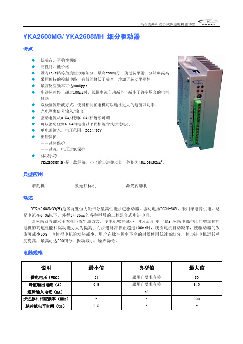
YKA2811MA细分驱动器特点◆ 高性能、低价格、低噪音、平稳性极好◆ 设有32档等角度恒力矩细分◆ 采用独特的控制电路,有效的降低了噪音,增加了转动平稳性◆ 最高反应频率可达200Kpps◆ 步进脉冲停止超过100ms时,线圈电流自动减半,减小了许多场合的电机过热◆ 双极恒流斩波方式,使得相同的电机可以输出更大的速度和功率◆ 光电隔离信号输入/输出◆ 驱动电流从0.5A/相到8.0A/相连续可调◆ 单电源输入,电压范围:AC60-130V◆ 出错保护:――过热保护――过流、电压过低保护典型应用雕刻机中型数控机床包装机抛光设备恒速应用简述YKA2811MA为一款等角度恒力矩细分型驱动器,最高细分数能达到200细分,驱动电压交流60V~130V,适配电流在8A以下、外径86~130mm的各种型号的两相混合式步进电机。
电器规格说明 最小值 典型值 最大值 供电电压(VAC) 60 100 130峰值输出电流(A) 0.5 跟用户要求有关 8.0逻辑输入电流(mA) 15步进脉冲相应频率(KHz)- - 200脉冲低电平时间(uS) 2.5 - -电流设定1. STOP/Im为保持状态输出电流设置电位器,可设置为正常输出电流的20%~80%(顺时针增大,逆时针减小)2. RUN/Im为正常工作输出电流设置开关(详见下表)R-1 0 1 2 3 4 5 6 7 8 9 A B C D E F Im(A) 0.5 1.0 1.5 2.0 2.5 3.0 3.5 4.0 4.5 5.0 5.5 6.0 6.5 7.0 7.58.0细分设定SK 0 1 2 3 4 5 6 7 8 9 A B C D E F 细分数200 100 8064 50 4032252016108 5 4 2 1DIP开关功能设定DP1 OFF:接受外部脉冲ON :驱动器内部自发7.5KHz脉冲DP2 OFF:脉冲信号+方向信号控制方式ON :正向脉冲+反向脉冲控制方式驱动器接线示意图输入信号波形时序图安装尺寸(单位:mm)指示灯和电位器功能说明标记符号 功 能 注 释 PWR 电源指示灯 驱动器通电时,绿色指示灯亮。