SysAidServerFree_Installation Guide
Testo Saveris 2配置指南说明书
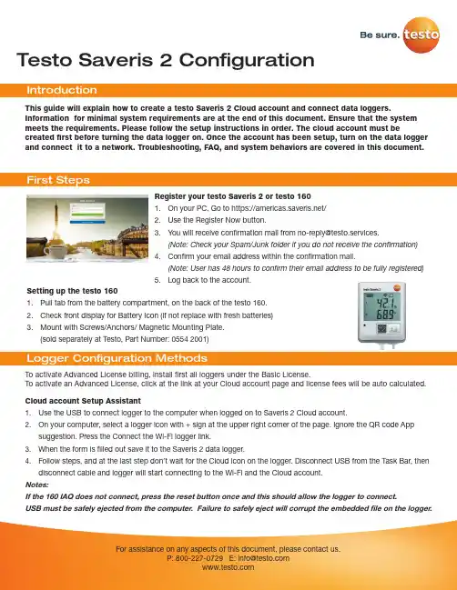
Testo Saveris 2 Configuration To activate Advanced License billing, install first all loggers under the Basic License. To activate an Advanced License, click at the link at your Cloud account page and license fees will be auto calculated.This guide will explain how to create a testo Saveris 2 Cloud account and connect data loggers.Information for minimal system requirements are at the end of this document. Ensure that the system meets the requirements. Please follow the setup instructions in order. The cloud account must becreated first before turning the data logger on. Once the account has been setup, turn on the data logger and connect it to a network. Troubleshooting, FAQ, and system behaviors are covered in this document.Register your testo Saveris 2 or testo 1601. On your PC, Go to https:///2. Use the Register Now button.3. *********************************************************.(Note: Check your Spam/Junk folder if you do not receive the confirmation)4. Confirm your email address within the confirmation mail.(Note: User has 48 hours to confirm their email address to be fully registered)5. Log back to the account.Setting up the testo 1601. Pull tab from the battery compartment, on the back of the testo 160.2. Check front display for Battery Icon (if not replace with fresh batteries)3. Mount with Screws/Anchors/ Magnetic Mounting Plate.(sold separately at Testo, Part Number: 0554 2001)Cloud account Setup Assistant1. Use the USB to connect logger to the computer when logged on to Saveris 2 Cloud account.2. On your computer, select a logger icon with + sign at the upper right corner of the page. Ignore the QR code Appsuggestion. Press the Connect the Wi-Fi logger link.3. When the form is filled out save it to the Saveris 2 data logger.4. Follow steps, and at the last step don’t wait for the Cloud icon on the logger. Disconnect USB from the Task Bar, thendisconnect cable and logger will start connecting to the Wi-Fi and the Cloud account.Notes:If the 160 IAQ does not connect, press the reset button once and this should allow the logger to connect.USB must be safely ejected from the computer. Failure to safely eject will corrupt the embedded file on the logger.To override auto selected Country temperature units setting go to User / User Settings and select the temperature unit from the drop-down selection.•The E-52 error shows that the logger is presently attached to another account.•To remove the logger from its original account, log on, go to Configuration / Wi-Fi data logger, select logger Details in the right column.•Press the Deactivate button at top of the page.•Scroll to the bottom of the page and press the red Remove Data Logger button.•Log out of the account and log back, and if the logger shows up grayed out at the Dashboard listing, click the arrow at the left to delete associated data.•Press shortly the logger button to complete transfer of the delete information.• The logger is now free to be attached to another account.Hot Spot Mode1. Log on to the testo Saveris 2 Cloud account and copy the Account ID (Configuration/Account ID), close the web page.2. Make sure the Wi-Fi adapter is turned on, and the Ethernet cable is pulled out.3. Press the logger button for more than 3 seconds to get LED into continuous green blinking. CONF message on thelogger display confirms the hot spot connection.4. On the computer at Wi-Fi connections connect to Testo Saveris 2 network.5. Open browser and enter 192.168.1.1 at the URL line.6. Fill the form and save, there will be confirmation message on the logger screen.7. A steady Cloud icon on the display indicates connectionNote:USB must be safely ejected from the computer. Failure to safely eject will corrupt the embedded file on the logger. USB Method (for connection to PC using Microsoft Windows OS Only)1. Copy Account ID from your testo Saveris 2 Cloud account (Configuration / Account ID)2. Logger USB connection – open WifiConf.pdf file3. Insert account ID to the form field, fill in name of the network (SSID) and network password. Save configuration(green button) to the logger using Windows File Explorer. Make sure that .xml file is saved to the Saveris 2 drive, not any other folder on your computer.4. Disconnect USB from the Task Bar, then disconnect cable.5. A steady Cloud icon on the display indicates connection to the Cloud website.Note:USB must be safely ejected from the computer. Failure to safely eject will corrupt the embedded file on the logger.testo Saveris 2 / testo 160 work only on 2.4 GHz Wi-Fi. Be sure to select a 2.4 GHz Wi-Fi network.Note: In most institutions, IT permission to install is required, especially on high security networks.NOTE: The MAC Address for the device can be found on the back label. Please keep the MAC Address available.The following browser and router ports must be open:• Browser (Microsoft Edge, Firefox, Google Chrome, Safari): MQTT Port 443 (https)• Router:Port 8883 TCP Secure MQTT (Message Queue Telemetry Transport over SSL)Port 123 UDP Network Time Protocol (NTP)Port 53 TCP Domain Name SystemPort 53 UDP Domain Name SystemCan the Wi-Fi data logger be connected to the PC using any USB cable?• We recommend that you use the USB cable supplied with the Wi-Fi data logger to guarantee stable data transmission.Longer USB cables are suitable for the power supply only.Can the Wi-Fi data logger also be used in networks with WPA2 Enterprise encryption?• testo 160 data loggers can be used in networks with the following WPA2 Enterprise encryption methods.WPA2 Enterprise: EAP-TLS, EAP-TTLS-TLS, EAP-TTLS-MSCHAPv2, EAP TTLS-PSK, EAP-PEAP0-TLS, EAP-PEAP0-MSCHAPv2, EAP-PEAP0-PSK, EAP-PEAP1-TLS, EAP-PEAP1-MSCHAPv2, EAP-PEAP1-PSK, WPA Personal, WPA2 (AES), WPA (TKIP), WEPThe XML configuration file is not being applied by the Wi-Fi data logger, what can I do?• Depending on the operating system, there may be difficulties with the data transfer if the configuration file name has been changed. Leave the default file name.The humidity sensor has been stored at a high temperature (> 30 °C) and in very high humidity (> 80% RH) for a long period of time, what can I do?• The sensor requires a long period of time to regenerate itself again. This process can be accelerated by storing the sensor in a well-ventilated location at a high temperature(> 30 °C} and in low humidity(< 20% RH) for at least 12 hours.The Wi-Fi data logger’s wireless connection to the access point was interrupted, what can I do?1. Press the control key on the Wi-Fi data logger to start searching for a Wi-Fi connection manually.2. Change the alignment or position of the Wi-Fi data logger or the access point (Wi-Fi router).Signal Description LED flashes green every 30 seconds (IAQ)Normal stateLED flashes green at one-second intervals (for 5 min, then 1 long red flash) Configuration mode (hotspot) - press button > 3 secLED flashes green every 200 ms (for 10 seconds)Configuration app: During hotspot mode pressbutton < 3 secLED gives 2 red flashes Connection to Wi-Fi failed (incorrect SSID, In-correct SSID password, incorrect account ID orincorrect account password, attempt to log the160IAQ into the testo Saveris 2 Cloud.If XML is correct, LED gives 1 long green flashIf XML is incorrect, LED gives 3 red flashesConfiguration via USB/PDFLED gives 2 green flashes Connection to Wi-Fi and Cloud successful LED gives 1 long red flash Alarm activated due to limit value violationLED gives 5 green flashes Reset Wi-Fi data logger to factory settingsPress key > 20 secLED gives 1 green flash (measurement data col-lected)Send measurement data to the testo Saveris 2 Cloud (website): press key < 3 secLED gives 4 red flashes Batteries expiredLED flashes alternately green and red Firmware update via USB or wirelessThe error codes can be read out using a web browser via a smartphone/tablet or PC. Press the probe button for 3 seconds. Then enter the following IP address 192.168.1.1 in the web browser.The Wi-Fi data logger (160 IAQ) is displaying error code E03, E04, E05 or E09, what can I do?• An error has occurred in the Wi-Fi data logger. The error will automatically be corrected by the firmware of the Wi-Fi data logger. After a few seconds, the error code should no longer be displayed, you do not need to do anything.The Wi-Fi data logger (160 IAQ) is displaying error code E12, what can I do?• The configuration file WifiConfig.xml indicates an error. Use the Quick Start Guide to create a new configuration file and save this on the Wi-Fi data logger.The Wi-Fi data logger (160 IAQ) is displaying error code E12, what can I do?• The configuration file WifiConfig.xml indicates an error. Use the Quick Start Guide to create a new configuration file and save this on the Wi-Fi data logger.The Wi-Fi data logger (160 IAQ) is displaying error code E23, what can I do?• The most common reason for this error is low battery. Insert new batteries into the Wi-Fi data logger.• If this does not solve the problem: Reset the Wi-Fi data logger to its factory settings. To do this, press and hold down the control key for> 20 s until the display goes blank. If the error code continues to be displayed, then there is a hardware problem. Please contact our Customer Service.The Wi-Fi data logger (160 IAQ) is displaying error code E26, what can I do?• The access point (Wi-Fi router) has no connection to the internet. Check the access point’s internet connection.• The routing within the network infrastructure is not working, check whether too many terminal devices are logged into the access point.The Wi-Fi data logger (160 IAQ) is displaying error code E32, what can I do?The Wi-Fi data logger has not obtained an IP address. There are 2 possible reasons for this error:• The network password is incorrect. Check the password of the Wi-Fi network. Use the Quick Start Guide to create a new configuration file with the correct password and save this on the Wi-Fi data logger.• The access point (Wi-Fi router) has a MAC filter or does not permit the integration of new devices. Check the settings for the access point.The Wi-Fi data logger (160 IAQ) is displaying error code E35, what can I do?• The Wi-Fi data logger has not received any reply to its test ping from the access point (Wi-Fi router). Make sure that a ping to the gateway is allowed within the access point configuration.The Wi-Fi data logger (160 IAQ) is displaying error code E36, what can I do?No DNS available or accessible. Contact the operator of the Wi-Fi network.The Wi-Fi data logger is displaying error code E41, what can I do? The Wi-Fi data logger cannot obtain any current time from a time server ().• The access point (Wi-Fi router) has no connection to the internet. Check the access point’s internet connection.• The NTP port (123/UDP) of the access point (Wi-Fi router) is not open. Check whether the NTP port (123/UDP) is opened.The Wi-Fi data logger (160 IAQ) is displaying error code E51, what can I do?The Wi-Fi data logger was not able to connect to the testo Saveris 2 Cloudd.• If the Wi-Fi data logger has already been connected to the testo Saveris 2 Cloud and this connection is suddenly no longer possible: The testo Saveris 2 Cloud servers are not currently accessible. The servers will be monitored and should be accessible again within a few hours.• If the Wi-Fi data logger has not yet been connected to the testo Saveris 2 Cloud: The TCP ports (1883 or 8883) of the access point (Wi-Fi router) are not open. Check whether the TCP ports (1883 or 8883) are open in both directions.The Wi-Fi data logger (160 IAQ) is displaying error code E52, what can I do?• The Wi-Fi data logger could not log into the testo Saveris 2 Cloud because it is already logged into another account.Please log the Wi-Fi data logger out of the existing account first.The Wi-Fi data logger (160 IAQ) is displaying error code E63, what can I do?The Wi-Fi data logger could not send any data to the testo Saveris 2 Cloud.• The internet connection was interrupted during the transmission. Check whether there is a stable connection from the Wi-Fi data logger to the access point (Wi-Fi router). Check the access point’s internet connection. The data will be transferred during the next communication cycle. Alternatively: Initiate data transmission manually by pressing the control key on the Wi-Fi data logger.• The testo Saveris 2 Cloud server was not able to process the request for data storage. The servers will be monitored and should be accessible again within a few hours.The Wi-Fi data logger (160 IAQ) is displaying error code E69, what can I do?• The Account ID contained in the configuration file is missing or is not valid. Create a new configuration file and save this on the Wi-Fi data logger.• An attempt was made to log the testo 160 E Wi-Fi data logger into the testo Saveris 2 Cloud without any external probes connected. Connect the required external probes before logging inThe Wi-Fi data logger (160 IAQ) is displaying error code E75, what can I do?• A firmware update for the Wi-Fi data logger failed.• The internet connection was interrupted during the transmission or the data was not received intact by the Wi-Fi data logger for other reasons. Check whether there is a stable connection from the Wi-Fi data logger to the access point (Wi-Fi router). Check the access point’s internet connection. The data will be transferred during the next communication cycle.• Alternatively: Initiate data transmission manually by pressing the control key on the Wi-Fi data logger.The Wi-Fi data logger (160 IAQ) is displaying the warning message Err AccountlD, what can I do?• The Account lD contained in the configuration file is not valid.• Use the Quick Start Guide to create a new configuration file and save this on the Wi-Fi data logger.The Wi-Fi data logger (160 IAQ) is displaying the warning message no AccountlD, what can I do?• There is no AccountlD in the configuration file.• Use the Quick Start Guide to create a new configuration file and save this on the Wi-Fi data logger.The Wi-Fi data logger (160 IAQ) is displaying the warning message no License, what can I do?• The Wi-Fi data logger cannot be logged in because the number of Wi-Fi data loggers permitted to log in has been exceeded or your testo 160 license has expired.• Log off another Wi-Fi data logger, extend or renew your testo 160 license.The Wi-Fi data logger (160 IAQ) is displaying the warning message not Active, what can I do?• The Wi-Fi data logger has been deactivated. It is not storing, and therefore not sending, any measurement data to the testo Saveris 2 Cloud.• Activate the Wi-Fi data logger (under Configuration --> Wi-Fi data logger) when the Wi-Fi data logger needs to store and send measurement data again.Testo Data Loggers will operate under free Basic License with limitations as listed at the table below.Register now: https:///。
IBM Maximo for Aviation 7.6.4 快速入门指南说明书
IBM Maximo for AviationVersion 7.6.4Quick Start GuideThis guide introduces IBM Maximo for Aviation Version 7.6.4, provides a link to a list of prerequisite software, gets you started with a typical installation, and provides a roadmap to other important information.National Language Version:To obtain the Quick Start Guide in other languages, print the language-specific PDF file from the installation media.Product overviewIBM ®Maximo ®for Aviation provides aviation organizations with features to schedule and manage aircraft maintenance to maintain regulatory compliance and minimize periods when an aircraft is grounded. The efficient maintenance, repair, and overhaul of aircraft increases flight availability and extends the life of airframes, engines, and other components of an aircraft.For complete information, including installation instructions, see IBM Knowledge Center (/support/knowledgecenter/SS5RRF_7.6.4/com.ibm.mavm.doc/welcome.html).2Step 2: Plan the installationYou install Maximo for Aviation on a Microsoft Windows administrative workstation. Ensure that IBM Maximo Asset Management version 7.6.0.6 is installed on the same administrative workstation where you plan to install Maximo for Aviation version 7.6.4, and in the same language as Maximo for Aviation version 7.6.4.You must have system administrator rights and privileges to install the product.For information about the hardware, software, and network requirements for your product, see the System Requirements section in the Overview and Planning page on the Maximo Asset Management wiki (https:///developerworks/community/wikis/home?lang=en#!/wiki/IBM%20Maximo%20Asset%20Management/page/Overview%20and%20planning)3Step 3: Install the productTo install Maximo for Aviation:1.Review the software requirements.2.Prepare to install.3.Install Maximo for Aviation.For Oracle WebLogic Server environments only: you must deploy the Enterprise Application Archive (EAR) files.For IBM WebSphere ®Application Server environments: The EAR files are installed when you install the process automation engine. If this task was deferred during the Maximo for Aviation installation, deploy the EAR files.Detailed installation instructions are in the IBM Maximo for Aviation, 7.6.4 Installation Guide in IBM Knowledge Center (/support/knowledgecenter/SS5RRF_7.6.4/com.ibm.mavm.doc/welcome.html).More informationAfter you install the product, use IBM Knowledge Center to learn more about the product.For more information, see the following resources:v Product support (https:///support/entry/portal/product/tivoli/ibm_maximo_for_aviation )v IBM User Communities (https:///social/aggregator/ibm)IBM®Maximo for Aviation Licensed Materials - Property of IBM. © Copyright IBM Corp. 2016. U.S. Government Users Restricted Rights - Use, duplication or disclosure restricted by GSA ADP Schedule Contract with IBM Corp.IBM, the IBM logo, and are trademarks or registered trademarks of International Business Machines Corp., registered in many jurisdictions worldwide. Other product and service names might be trademarks of IBM or other companies. A current list of IBM trademarks is available on the Web at “Copyright and trademark information” (/legal/copytrade.shtml).Printed in Ireland。
ELCM Release 14.4.0.0.0 安装指南说明书
ELCM Installation Oracle Banking ELCM Release 14.4.0.0.0[Apr] [2020]Table of Contents1.FLEXCUBE UBS INSTALLATION ............................................................................................................. 1-1 1.1I NTRODUCTION........................................................................................................................................... 1-1 1.2D EPLOYMENT O PTIONS .............................................................................................................................. 1-11.2.1Centralized ......................................................................................................................................... 1-11.2.2Decentralized ..................................................................................................................................... 1-21.2.3Hybrid ................................................................................................................................................ 1-2 1.3O RACLE FLEXCUBE I NSTALLATION V ARIETIES....................................................................................... 1-31.3.1Creating New Installation Directory ................................................................................................. 1-31.3.2Creating Patch-set Directory ............................................................................................................. 1-31.3.3New Installation ................................................................................................................................. 1-41.3.4Cloning Existing Environment ........................................................................................................... 1-41.3.5Applying Patchset .............................................................................................................................. 1-4 1.4C OMPONENTS OF O RACLE FLEXCUBE ..................................................................................................... 1-51.4.1Plug-Ins Required .............................................................................................................................. 1-51.4.2Setting up the Plug-Ins ....................................................................................................................... 1-61.4.3Manual Deployment ........................................................................................................................... 1-61.4.4FCUBS Application Installation ........................................................................................................ 1-71.4.5GATEWAY Application Installation .................................................................................................. 1-81.4.6Restful Services .................................................................................................................................. 1-91.4.7SWITCH Interface Installation .......................................................................................................... 1-9FCUBS Process Flow Deployment .................................................................................................................... 1-91. FLEXCUBE UBS Installation 1.1 IntroductionThis manual is designed to help acquaint you with the various deployment options supported by the installer, the various components that make FLEXCUBE UBS, the plug-ins that are supported by these components and the detailed installation steps of the various components supported by Oracle FLEXCUBE.1.2 Deployment OptionsCentralized In this mode there will be only one setup. The build, configurationand deployment would be targeted to this setup alone.De-Centralized Here there would be 2 setups, i.e. Host and Branch. Build,configuration and deployment would be done separately for each ofthese setup.Hybrid Combination of both the above said. Build, configuration anddeployment would be based on what is handled by each of thesetup.1.2.1 Centralized1.2.2 Decentralized1.2.3 Hybrid1.3 Oracle FLEXCUBE Installation VarietiesInstalling FLEXCUBE can happen in multiple varieties. Please follow steps mentioned in first 3 sections before starting any installation steps.Installer does not accept spaces in file path. Its applicable for all path including but not limited to source path, temp destination directory, property file path etc.The below screenshot shows sample “OSDC.zip” folder structure. This is the location to bepointed, if installer asks for FC Home directory.In the above screenshot, main release content can be found directly under this directory.1.3.1 Creating New Installation DirectoryExtract the ZIP file FCUBS_<Version>.zip1. Create a FCUBS_<Version> Folder and extract the above zip into this folder.2. Make sure that FCUBS_<Version> Directory is accessible by both Application serverand Database Server.1.3.2 Creating Patch-set Directory1. Extract the ZIP file FCUBS_<Patch No>.zip into FCUBS_<Patch No> folder.2. Make Sure that the FCUBS_<Patch No> folder should be kept parallel toFCUBS_<Version> folder as shown below.1.3.3 New InstallationThis section explains the step by step procedure for fresh installation using installer:1. Apply the environment settings for FLEXCUBE. (Refer to the documentFCUBS_Installer_Prerequisite).1.3.4 Cloning Existing Environment1. Navigate to the folder which was chosen as FCUBS_<Version> and Launch the installer byrunning FCUBSInstaller.bat in the Installer folder.2. Import a dump of FLEXCUBE database. (Refer ‘Installing Oracle FLEXCUBE Database’chapter of FCUBS_DB_Setup)3. Create two FLEXCUBE Users using Installer.(Refer User_Creation_Utility document underUtilities).4. Get the Property file of the Environment to be cloned and Modify the property file by loading itin the Installer.5. Update the Ear file with the New Property File.6. Deploy the Built EAR in application server and login to the FLEXCUBE.7. Login into FLEXCUBE using the users created as part of step3 and reset/Modify thePassword of all the users.1.3.5 Applying PatchsetThis section describes applying patchset. The PATCHSET_INSTALLATION flag should be Y in env.properties.1.3.5.1 Applying FLEXCUBE Patch Set - MiddlewareWeblogic1. Navigate to the Patch Set folder FCUBS_<Patch No> and Launch the installer by runningFCUBSInstaller.bat in the Installer folder.2. Provide the path of the FCUBS_<Patch No> folder as Source Path.3. Build an EAR by loading the existing property file.4. Deploy the built EAR in weblogic application server.Building of EAR can be done in remote location but the application deployment should be done in local system where the application server in installed.Websphere1. Navigate to the folder which was chosen as FCUBS_<Patch No> and Launch the installer byrunning FCUBSInstaller.bat in the Installer folder.2. Provide the path of the FCUBS_<Patch No> folder as Source Path.3. Build an EAR by loading the existing property file4. Deploy the built EAR in websphere application server.1.3.5.2 Applying FLEXCUBE Patch set - DATABASE1. Navigate to the folder which was chosen as FCUBS_<Patch No> and Launch the installer byrunning FCUBSInstaller.bat in the Installer folder.2. Compile the Data Base Objects by Referring to FCUBS_DB_Compilation Document.3. Provide the path of the FCUBS_<Patch No> folder as Source Path.4. Provide Database server connection details5. Apply the patch set into the Database server.1.4 Components of Oracle FLEXCUBEFollowing are the components of the oracle FLEXCUBE:•Open Development Tool (ODT)•FLEXCUBE Universal Banking Solution (FCUBS)•GATEWAY•Restful Services•SWITCH Interface Installation•Standalone Scheduler1.4.1 Plug-Ins RequiredApplication Plug-ins SupportedOpen Development Tool Not applicableOracle FLEXCUBE Universal Banking •Branch •BPEL •Scheduler •Reports •FGL •OFTW •DMS •InsulationOracle FLEXCUBE ELCM •BPEL•Scheduler•FGL•Reports•OFTW•DMSOracle Banking Treasury •Scheduler•ReportsOracle Banking Trade Finance •Scheduler•Reports•DMSGateway Not applicableRestful Services Not applicableSwitch Interface Installation Not applicableStandalone Scheduler Not applicable1.4.2 Setting up the Plug-InsThe Setting_up_Plugins document describes the step by step details of setting up the various plug-ins supported by FLEXCUBE. This is under FCUBS Main.1.4.3 Manual DeploymentThis section explains the steps to deploy Oracle FLEXCUBE UBS application manually.Application server resources required are detailed in “Resources_To_Be_Created”document.This is present under Environment Setup > Application ServerFollow the document “FCUBS_Manual_Deployment_WL” for Weblogic.For Websphere please follow “FCUBS_Manual_Deployment_WAS”.For Tomcat, please refer to the document “Branch_Deployment_on_Tomcat”.Tomcat is supported only for Deployment of Decentralized branch war file. FCUBS EAR deployment is only on Weblogic or Websphere.All these documents are present in the Environment Setup > Application Server.1.4.4 FCUBS Application InstallationAll documents can be referred under FCUBS Components > FCUBS.This Section describes the various operations performed for FCUBS application. Thisapplication is operated in two modes during property file creation:•Custom mode: All inputs are provided by the user.•Default Mode: Property file is created by considering the default properties. User inputs are minimal.Database Installation This document gives the step by step instructions for setting up FCUBS Data Base. It also explains the process of importing full dump, and also explains the process of loading static data. Refer to the document FCUBS_DB_SetupBuilding Property File This section explains the detailed instructions to be followed for Building FCUBS Property file , it explains the instructions for setting up the property file with plug-ins and plug-in related properties. Refer to the document FCUBS_Property_File_CreationBuilding Ear This section explains the detailed instructions to be followed for Building FCUBS EAR, it explains the step by step instructions for building the EAR with the corresponding property file. Refer to the document FCUBS_EAR_BuildingApplication Deployment Weblogic FULLDeploymentThis section gives the detailedinstructions for FULL deployment ofUBS application in weblogic server, italso explains the basic instructions forcreating the resources required fordeployment of UBS application. Referto the documentFUBS_Application_Deployment_WeblogicPatch/PatchsetDeploymentThis section gives the detailedinstructions for Partial deployment ofUBS application, It explains the stepsfor deployment of the patches of theexisting ear in weblogic server. Referto the documentFUBS_Application_Deployment_WeblogicWebsphere FULLThis section gives the detailed1.4.5 GATEWAY Application InstallationAll documents can be referred under FCUBS Components > Restful Services.Building Ear This section explains the detailed instructions to be followed for BuildingRestful Service EAR, it explains the step by step instructions forbuilding the EAR. Refer to the documentRESTService_Compliation_BuildApplication Deployment WeblogicThis section gives the detailed instructions for FULLdeployment of Restful application in weblogic server.Refer to the documentRESTService_Deployment_WeblogicWebsphereThis section gives the detailed instructions for FULLdeployment of Restful application in websphere server.Refer to the documentRESTService_Deployment_WebsphereDeployment instructions for FULL deployment ofUBS applicationin websphere server,it explain the steps to be followed fordeploying UBS application inwebsphere server using installerRefer to the documentFUBS_Application_Deployment_WebspherePatch/PatchsetDeploymentThis section gives the detailedinstructions for partial deployment ofUBS application in websphere server,it explains the steps to be followed fordeploying the patches for the existingapplication in websphere server.Refer to the documentFUBS_Application_Deployment_WebsphereBuilding Property file This section explains the detailed instructions to be followed for Building GATEWAY Property file, it explains the instructions for setting up the property file with plug-ins and plug-in related properties. Refer to the document GATEWAY_Property_File_Creation1.4.6 Restful Services1.4.7 SWITCH Interface InstallationAll documents can be referred under FCUBS Components > Switch.FCUBS Process Flow DeploymentAll documents can be referred under FCUBS Components > Scheduler.GATEWAY Application InstallationStandalone Scheduler InstallationBuilding Ear forMonitor This section explains the detailed instructions to be followed for Building Monitor EAR, it explains the step by step instructions forbuilding the EAR with the corresponding property file. Refer to thedocument Switch_Monitor_InstallationFor running Monitor setup, switch EAR should be available FCUBS ProcessFlow Deployment This section describes the instructions for FCUBS process flow deployment, it also provides detailed description on deploying FCUBSBPEL process flows onto a weblogic server configured with SOA suitecomponents . It covers different approaches for deploying a process.Refer to the document FCUBS_ProcessFlow_Deployment under FCUBS Main.BuildingProperty file This section explains the detailed instructions to be followed for Building Scheduler Property file, it explains the instructions for setting up theproperty file with plug-ins and plug-in related properties. Refer to thedocument Scheduler_Property_File_CreationELCM Installation[Apr] [2020]Version 14.4.0.0.0Oracle Financial Services Software LimitedOracle ParkOff Western Express HighwayGoregaon (East)Mumbai, Maharashtra 400 063IndiaWorldwide Inquiries:Phone: +91 22 6718 3000Fax: +91 22 6718 3001https:///industries/financial-services/index.htmlCopyright © [2007], [2020], Oracle and/or its affiliates. All rights reserved.Oracle and Java are registered trademarks of Oracle and/or its affiliates. Other names may be trademarks of their respective owners.U.S. GOVERNMENT END USERS: Oracle programs, including any operating system, integrated software, any programs installed on the hardware, and/or documentation, delivered to U.S. Government end users are "commercial computer software" pursuant to the applicable Federal Acquisition Regulation and agency-specific supplemental regulations. As such, use, duplication, disclosure, modification, and adaptation of the programs, including any operating system, integrated software, any programs installed on the hardware, and/or documentation, shall be subject to license terms and license restrictions applicable to the programs. No other rights are granted to the U.S. Government.This software or hardware is developed for general use in a variety of information management applications. It is not developed or intended for use in any inherently dangerous applications, including applications that may create a risk of personal injury. If you use this software or hardware in dangerous applications, then you shall be responsible to take all appropriate failsafe, backup, redundancy, and other measures to ensure its safe use. Oracle Corporation and its affiliates disclaim any liability for any damages caused by use of this software or hardware in dangerous applications.This software and related documentation are provided under a license agreement containing restrictions on use and disclosure and are protected by intellectual property laws. Except as expressly permitted in your license agreement or allowed by law, you may not use, copy, reproduce, translate, broadcast, modify, license, transmit, distribute, exhibit, perform, publish or display any part, in any form, or by any means. Reverse engineering, disassembly, or decompilation of this software, unless required by law for interoperability, is prohibited.The information contained herein is subject to change without notice and is not warranted to be error-free. If you find any errors, please report them to us in writing.This software or hardware and documentation may provide access to or information on content, products and services from third parties. Oracle Corporation and its affiliates are not responsible for and expressly disclaim all warranties of any kind with respect to third-party content, products, and services. Oracle Corporation and its affiliates will not be responsible for any loss, costs, or damages incurred due to your access to or use of third-party content, products, or services.。
Oracle Argus Safety 8.1 用户指南说明书

U.S. GOVERNMENT END USERS: Oracle programs, including any operating system, integrated software, any programs installed on the hardware, and/or documentation, delivered to U.S. Government end users are "commercial computer software" pursuant to the applicable Federal Acquisition Regulation and agency-specific supplemental regulations. As such, use, duplication, disclosure, modification, and adaptation of the programs, including any operating system, integrated software, any programs installed on the hardware, and/or documentation, shall be subject to license terms and license restrictions applicable to the programs. No other rights are granted to the U.S. Government.
Oracle Banking Origination Release 14.5.3.0.0安装指南说
Security Management System Services Installation GuideOracle Banking Origination Release 14.5.3.0.0Part Number F51366-01November 2021Table of Contents1.PREFACE ........................................................................................................................................................ 1-1 1.1I NTRODUCTION ......................................................................................................................................... 1-1 1.2A UDIENCE................................................................................................................................................. 1-1 1.3D OCUMENTATION A CCESSIBILITY ............................................................................................................ 1-1 1.4O RGANIZATION......................................................................................................................................... 1-11.5R ELATED D OCUMENTS ............................................................................................................................. 1-12.DATABASE SETUP ........................................................................................................................................ 2-1 2.1I NTRODUCTION ......................................................................................................................................... 2-1 2.2P REREQUISITE........................................................................................................................................... 2-12.3D ATABASE S ETUP ..................................................................................................................................... 2-13.DOMAIN AND CLUSTER CONFIGURATION ......................................................................................... 3-1 3.1SMS D OMAIN C ONFIGURATION................................................................................................................ 3-13.1.1Prerequisites ......................................................................................................................................... 3-13.1.2Steps to Create Domain ....................................................................................................................... 3-14.DATA SOURCES CREATION ...................................................................................................................... 4-1 4.1P REREQUISITE........................................................................................................................................... 4-14.2D ATA SOURCES L IST................................................................................................................................. 4-15.DEPLOYMENTS ............................................................................................................................................ 5-1 5.1P REREQUISITE........................................................................................................................................... 5-1 5.2D EPLOYMENTS L IST.................................................................................................................................. 5-15.3S TEPS TO D EPLOY AS A PPLICATION.......................................................................................................... 5-16.RESTARTS AND REFRESH ......................................................................................................................... 6-16.1R ESTARTING S ERVERS.............................................................................................................................. 6-17.LOGGING AREA ........................................................................................................................................... 7-1 7.1I NTRODUCTION ......................................................................................................................................... 7-17.1.1Logging Area ....................................................................................................................................... 7-11. Preface 1.1 IntroductionThis guide helps you to install the SMS Core services on designated environment. It is assumed that all the prior setup is already done related to WebLogic installation, WebLogic managedserver creation and Oracle DB installation.It is recommended to use dedicated managed server for SMS Core services.Note: For the exact version to be installed, refer to Software Prerequisites section in LicenseGuide.1.2 AudienceThis document is intended for WebLogic admin or ops-web team who are responsible forinstalling the OFSS banking products.1.3 Documentation AccessibilityFor information about Oracle's commitment to accessibility, visit the Oracle Accessibility Program website at /pls/topic/lookup?ctx=acc&id=docacc.1.4 OrganizationThis installation user guide would allow you to install following services in same order1. SMS Core Service.1.5 Related Documents•ANNEXURE-12. Database Setup 2.1 IntroductionIn this section you are going to setup database related configuration for SMS Installation. It isrecommended to create separate schema for SMS database setup.2.2 PrerequisiteBefore you proceed with below setup, ensure schemas has been created.In this section, you are going to setup database related configuration for SMS. Before you proceed, ensure the pre-installation setup is done. The pre-installation setup includes the configuration of database. After creating the schema for each of the required micro services, DDLs and INCs of each micro-service to be compiled in the respective schemas. The DDLs and INCs ensure the creation of tables and availability of static data required for the execution of services. These are compiled automatically using flyway.2.3 Database SetupTo setup DB for SMS below step need to be followed:Service Name Schema RequiredSMS-CORE-SERVICE Yes3. Domain and Cluster Configuration 3.1 SMS Domain Configuration3.1.1 Prerequisites1. Machine should have Java JDK has installed.2. Oracle Fusion Middleware has to be installed on the machine.NOTE: Before proceeding with below steps complete Oracle Banking Microservices Servicesinstallation guided.3. Steps for creating domain, properties like port numbers, names will be changing based on thedomain. Screenshots provided for such deviations. Domain creation process remains thesame.NOTE: For the exact version to be installed, refer to Software Prerequisites section inLicense Guide.3.1.2 Steps to Create DomainIt is recommended to have different managed server in one domain for SMS application. ForCreating Domain and Configuration, refer to How to create and Cluster Configuration sectionin ANNEXURE-14. Data Sources Creation4.1 PrerequisiteBefore you proceed with below setup, ensure the domain and server are created.4.2 Data sources ListThe table below lists the data sources to be created on each domain prior to deployment of applications onto managed servers.Data source NameData source JNDITargetsPLATOjdbc/PLATOSMS ManagedServer, API Gateway ServerSMSAccording to the JNDI created for each entity. For DEFAULTENTITY the JNDI should be jdbc/SMSPLATO_UI_CONFIGjdbc/PLATO_UI_CONFIGFor creating data source, refer to How to create Data sources section in ANNEXURE-1.5. Deployments 5.1 PrerequisiteBefore you proceed with below, make sure that previous steps are completed.5.2 Deployments ListBelow table give details of the deployments required on each domain for the SMS application torun. Refer to the exact version of archive names available as a part of release.Application Archive name OSDC pathSMS-CORE-SERVICES sms-core-services-{version}.war {Unzip the OSDC file} SMS\5.3 Steps to Deploy as ApplicationTo deploy application, refer to How to deploy section in ANNEXURE-1.6. Restarts and RefreshOnce everything is deployed, restart all the managed servers. For each application, call path“/refresh” for refreshing the configuration properties.6.1 Restarting ServersTo restart the server, refer to How to restart section in ANNEXURE-1.7. Logging Area 7.1 IntroductionThis part of the document will talk about the logs area where after deployment of SMSApplications in WebLogic server.7.1.1 Logging AreaSMS Application writes logs in the below area of the server-<WEBLOGIC_DOMAIN_CONFIG_AREA/servers/SMSAPP/logs/SMSAPP.outLet’s assume a domain has been created sms_domain with managed_server name calledSMSAPP in the following area of the server/scratch/oracle/middleware/user_projects/domains/sms_domain”. Logging area for SMS wouldbe/scratch/oracle/middleware/user_projects/domains/sms_domain/servers/SMSAPP/logs/SM SAPP.out.Security Management System Services Installation GuideOracle Financial Services Software LimitedOracle ParkOff Western Express HighwayGoregaon (East)Mumbai, Maharashtra 400 063IndiaWorldwide Inquiries:Phone: +91 22 6718 3000Fax: +91 22 6718 3001https:///industries/financial-services/index.htmlCopyright © 2021, Oracle and/or its affiliates. All rights reserved.Oracle and Java are registered trademarks of Oracle and/or its affiliates. Other names may be trademarks of their respective owners.U.S. GOVERNMENT END USERS: Oracle programs, including any operating system, integrated software, any programs installed on the hardware, and/or documentation, delivered to U.S. Government end users are "commercial computer software" pursuant to the applicable Federal Acquisition Regulation and agency-specific supplemental regulations. As such, use, duplication, disclosure, modification, and adaptation of the programs, including any operating system, integrated software, any programs installed on the hardware, and/or documentation, shall be subject to license terms and license restrictions applicable to the programs. No other rights are granted to the U.S. Government.This software or hardware is developed for general use in a variety of information management applications. It is not developed or intended for use in any inherently dangerous applications, including applications that may create a risk of personal injury. If you use this software or hardware in dangerous applications, then you shall be responsible to take all appropriate failsafe, backup, redundancy, and other measures to ensure its safe use. Oracle Corporation and its affiliates disclaim any liability for any damages caused by use of this software or hardware in dangerous applications.This software and related documentation are provided under a license agreement containing restrictions on use and disclosure and are protected by intellectual property laws. Except as expressly permitted in your license agreement or allowed by law, you may not use, copy, reproduce, translate, broadcast, modify, license, transmit, distribute, exhibit, perform, publish or display any part, in any form, or by any means. Reverse engineering, disassembly, or decompilation of this software, unless required by law for interoperability, is prohibited.The information contained herein is subject to change without notice and is not warranted to be error-free. If you find any errors, please report them to us in writing.This software or hardware and documentation may provide access to or information on content, products and services from third parties. Oracle Corporation and its affiliates are not responsible for and expressly disclaim all warranties of any kind with respect to third-party content, products, and services. Oracle Corporation and its affiliates will not be responsible for any loss, costs, or damages incurred due to your access to or use of third-party content, products, or services.。
Pulse Secure MAC OS Installation Guide
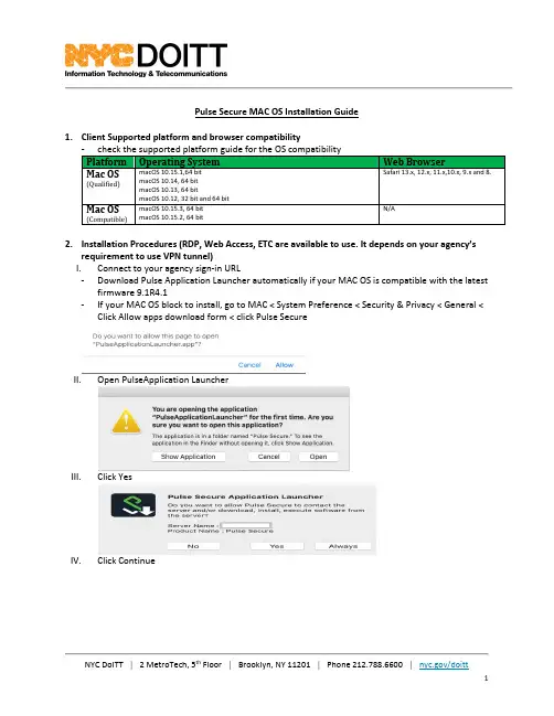
Pulse Secure MAC OS Installation Guide1. Client Supported platform and browser compatibility- check the supported platform guide for the OS compatibility Platform Operating SystemWeb BrowserMac OS(Qualified)macOS 10.15.1,64 bit macOS 10.14, 64 bit macOS 10.13, 64 bitmacOS 10.12, 32 bit and 64 bit Safari 13.x, 12.x, 11.x,10.x, 9.x and 8.Mac OS(Compatible)macOS 10.15.3, 64 bit macOS 10.15.2, 64 bitN/A2. Installation Procedures (RDP, Web Access, ETC are available to use. It depends on your agency’srequirement to use VPN tunnel)I. Connect to your agency sign-in URL- Download Pulse Application Launcher automatically if your MAC OS is compatible with the latestfirmware 9.1R4.1- If your MAC OS block to install, go to MAC < System Preference < Security & Privacy < General <Click Allow apps download form < click Pulse SecureII. Open PulseApplication LauncherIII. Click YesIV. Click ContinueV.Provide your User Name to install Pulse Secure ClientVI.Downloading Pulse SecureVII.Click Ok-Certification is important for your secure connection. Make sure you are using the correct certificationVIII.Check your system tray on the top after you install the pulse secure clientIX.Check Your Connectivity once you connect to the Pulse Secure ConnectX.Check your VPN Session3.Manual Installation-Download Pulse Secure Package from Service portal or Download from the new staging PCS: https:///assets/vpn/sc.html-Direct Client Download:https://sra1.nycnet/dana-cached/psal/PulseSecureAppLauncher.dmg1)Install your Installation Package2)Click your package3)Manually Install PulseSecure Package4)Provide your admin Credential to install Pulse Secure Client5)Install Pulse Secure Client6)Delete the Installation Package after the installation is done7)Provide your Agency URL4.Update Pulse from old version to the latest version-If your MAC OS is not compatible, you cannot use the old version of APP. Please uninstall the client and install the new package by using the above procedure。
Sybase安装
假设Sybase安装目录为C:\Sybase,数据库目录为Z:\data。
Adaptive Server名为SYBASE,Replication Server名为SYBASERS一.Adaptive Server的安装1. 安装Adaptive Server Enterprise 12.5。
选择自定义安装,在语言模块中只选简体中文,其他默认。
安装后先不进行配置,先打补丁,将ebf11339\server 下的所有文件覆盖复制到C:\Sybase安装目录。
2. 将”服务器配置”的快捷方式”起始位置”改为:C:\sybase\ASE-12_5\bin。
运行“服务器配置”,添加Adaptive Server,目录为Z:\data. 按如下参数配置Adaptive Server:Network port:本机IP,5000,xpserver port:本机IP,50033. 运行Sybase Central Java, 改变master数据库的大小为20M, 剩下的master设备空间分配给tempdb. 从sqlAdvance连接到新建的SqlServer,运行dump tran master with truncate_only以清除日志。
dump tran MBFEWKDB with no_log4. 运行”服务器配置”, 改变Adaptive Server和Backup Server的字符集为:UTF8, 排序规则:nocase。
二.Replication Server的安装1. 安装Replication Server. 选择自定义安装,在语言模块中只选简体中文,提示”请求重新安装组件…”选择全部肯定。
安装后打补丁,将ebf11683下的所有文件覆盖复制到C:\Sybase安装目录。
2. 启动Adaptive Server,运行Sybase Central Java, 新建用于Replication 的数据库:SYBASERS_RSSD。
Stormshield Management Center 2.8.2 安装指南说明书
GUIDESTORMSHIELD MANAGEMENTCENTER INSTALLATION GUIDE Version2.8.2Document last update:April26,2021Reference:sns-en-SMC-installation_guide-v2.8.2SMC-INSTALLATION GUIDE-V2.8.2 Table of contents1.Getting started32.Deploying the SMC server on the virtual environment42.1Deploying the.OVA file in the VMware virtual environment42.2Deploying.VHD files in the Microsoft Hyper-V virtual environment42.3Deploying.qcow2files in the KVM virtual environment53.Initializing the SMC server from the virtual environment63.1Initializing the SMC server automatically63.2Initializing the SMC server manually64.Ending the SMC server initialization8In the documentation,Stormshield Management Center is referred to in its short form:SMC andStormshield Network in its short form:SN.1.Getting startedSMC server allows you to perform a centralized administration of SN firewalls.From the SMC server 2.8.2web interface,you can:l Administer firewalls,l Get a clear overview of all your firewalls,l Ensure consistent configurations,l Access the web administration interface of firewalls.The SMC server is a virtual machine provided in the form of an .OVA archive file (Open Virtualization Archive)for VMware,.VHD (Virtual Hard Disk)for Microsoft Hyper-V or .qcow2for KVM.The SMC server 2.8.2is compatible with Stormshield Network Security in at least version 2.5.0.In order to install the SMC server,download the file smc-x.x.x.ova ,the archive smc-x.x.x-hyperv.zip or the archive smc-x.x.x-kvm.tar.gz from your personal area MyStormshield .SMC -INSTALLATION GUIDE -V 2.8.21.GETTING STARTED2.Deploying the SMC server on the virtual environmentYou must first deploy the SMC server on a VMware,Microsoft Hyper-V or KVM virtual environment.We recommend that you install the SMC server in a DMZ.2.1Deploying the.OVA file in the VMware virtual environmentDeploy the.OVA file in one of the following virtual environments:l VMware ESXi versions6.0,6.5and6.7The SMC virtual machine requires:l A processor,l An Ethernet network interface,l RAM:1024MB,l Minimum disk space required on the VMware environment:130GB.We recommend two processors and2GB of RAM for better performances.1.Open the VMware vSphere client on your administration workstation.2.Indicate the parameters for connecting to the VMware ESXi server on which you wish to installthe SMC server.3.In the File menu,select Deploy an OVF template.4.In the VMware deployment wizard,complete the steps for deploying the.OVA file.2.2Deploying.VHD files in the Microsoft Hyper-V virtual environmentThe smc-x.x.x-hyperv.zip archive contains two.vhd files:l smc-system.vhd,l product-data.vhd.Deploy the.VHD files in one of the following virtual environments:l Microsoft Hyper-V for Windows Server2012R2,l Microsoft Hyper-V for Windows Server2016.1.In the Hyper-V Manager tool,select a hypervisor.2.Create a new virtual machine and follow the steps shown in the wizard.l In the Assign Memory menu,allocate1024MB of memory.l In the Connect Virtual Hard Disk menu,select Use an existing virtual hard disk and selectthe smc-system.vhd file.3.Finish the creation of the new virtual machine.4.Open the parameters of this machine and go to the IDE0Controller menu.5.Click on Add then select Virtual hard disk in the Media section,and select the product-data.vhd file.6.Confirm,then log on to the machine.2.3Deploying.qcow2files in the KVM virtual environmentThe smc-x.x.x-kvm.tar.gz archive contains two.qcow files:l smc-system.qcow2,l product-data.qcow2.Deploy the.qcow2files in the following virtual environment:l Red Hat7.4and upwards.1.In the virt-manager tool,select the KVM hypervisor.2.Create a new virtual machine and follow the steps shown in the wizard.l Select Import existing disk image and select the smc-system.qcow2file.l Allocate at least1024MB of memory and select the number of CPU.3.Finish the creation of the new virtual machine.4.Open the parameters of this machine and go to the Add Hardware menu.5.Click on Storage,and select Select or create custom storage.Select the product-data.qcow2file.6.Confirm,then log on to the machine.We recommend you to use the e1000virtual network interface.3.Initializing the SMC server from the virtual environmentThe SMC virtual machine is deployed.You will now need to initialize the server either manually or automatically from the virtual environment.At the end of this procedure,you can connect to the server web interface from one of thesupported web browsers:l Microsoft Edge,latest stable version,l Google Chrome,latest stable version,l Mozilla Firefox,latest stable version.TIPWhen initializing the SMC server,a temporary IP address can be assigned either manually or by a DHCP server.In order for the DHCP assignment to work,connect the server's first virtual interface (eth0)to the right network in the virtual infrastructure.The definitive static IP address will beassigned in the SMC server initialization wizard described in section Ending the SMC serverinitialization.3.1Initializing the SMC server automatically1.Start the SMC virtual machine.2.By default,if the server first interface is configured to get an IP address from the DHCP server,no action is required from you to initialize the server.3.When the SMC server is initialized,connect to the address displayed in red from a webbrowser to carry on initialization.3.2Initializing the SMC server manually1.Start the SMC virtual machine.2.You have five seconds to go into manual initialization mode.If you let these five secondslapse,an attempt will be made to automatically assign an IP address via DHCP.If this attempt is unsuccessful,the manual initialization mode will then be suggested automatically.3.Define the following parameters:l The keyboard language used when you connect to the SMC server in command line, l The parameters of the eth0interface:IP address,subnet mask and default gateway,l The time zone for setting the date,l Whether the date will be configured manually or via an NTP server:o If manual configuration:enter a date,o If via an NTP server:enter one or several NTP servers(IP addresses or DNS names separated by commas).The NTP server can also be configured after the server hasbeen initialized.Refer to the SMC Administration guide for more information.4.When the SMC server is initialized,connect to the address displayed in red from a webbrowser to carry on initialization.4.Ending the SMC server initializationYou are now connected to the SMC server from a web browser for the first time.To complete the last steps of the SMC server initialization,use the SMC server initialization wizard.1.Select the manual initializationmode.2.Select the web interface language.The default language is your browser's language.If the browser's language is other than English or French,the default language is English.3.Select the keyboard language used when you connect to the SMC server in command line,4.Enter the definitive IP address of the SMC server.5.Specify the "admin"and "root"users'passwords:l admin:main administrator of the web interface.The password must have a minimum length of eight characters.l root:user allowed to connect to the server in command line.6.Click Apply .This completes initialization.7.Connect to the SMC server web interface with the "admin"user and password specified at step 5of this procedure.Your SMC server is now initialized.Learn how to administer firewalls and maintain the server in the Stormshield Management Center Administration guide .SMC -INSTALLATION GUIDE -V 2.8.24.ENDING THE SMC SERVER INITIALIZATIONSMC-INSTALLATION GUIDE-V2.8.2****************************All images in this document are for representational purposes only,actual products may differ. Copyright©Stormshield2021.All rights reserved.All other company and product namescontained in this document are trademarks or registered trademarks of their respectivecompanies.。
Inspur KDB_v1.0_SP1_Installation Guide_v2.1.4_cn
Open Source Software Notice This product includes open source software developed and/or licensed by "OpenSSL," "RSA Data Security, Inc.," "Apache Foundation," "Jean-loup Gailly and Mark Adler," and "Paul Heieh's hash". Information about the afore mentioned and the related open source software can be found in the "${INSTALL_PATH}/license/oss_licenses" directory. 本产品里包含着由“OpenSSL”、“RSA Data Security, Inc.”、“Apache Foundation”、 “Jean-loup Gailly 和 Mark Adler” 以及“Paul Heieh's hash”所开发或者许可的开放源码和软件。有关详细信息,请参看产品目录“${INSTALL_PATH}/li cense/oss_licenses”里的说明内容。
Oracle Banking Liquidity Management Release 14.4.0
Getting Started With Installation Guide Oracle Banking Liquidity ManagementRelease 14.4.0.0.0Part No. F30579-01[May] [2020]Table of Contents1.INSTALLATION PROCESS ......................................................................................................................... 1-1 1.1I NTRODUCTION........................................................................................................................................... 1-1 1.2P RE-R EQUISITE........................................................................................................................................... 1-1 1.3OSDC P ACKAGE ........................................................................................................................................ 1-1 1.4P LATO S ERVICES TO BE I NSTALLED............................................................................................................ 1-1 1.5SMS S ERVICE TO BE INSTALLED................................................................................................................. 1-2 1.6C OMMON C ORE S ERVICES TO BE INSTALLED.............................................................................................. 1-3 1.7OBLM S ERVICES TO BE INSTALLED ........................................................................................................... 1-4 1.8IC S ERVICES TO BE INSTALLED................................................................................................................... 1-5 1.9A PP-SHELL TO BE INSTALLED ..................................................................................................................... 1-6 1.10I NITIAL S ETUP ............................................................................................................................................ 1-6 1.11F ILE U PLOAD S ETUP................................................................................................................................... 1-61.Installation Process1.1 IntroductionThis document details out the order in which the user should carry on the installation process. 1.2 Pre-RequisiteAll software required for the application setup is installed. Refer the Release Notes for thesoftware to be installed.1.3 OSDC PackageExtract the OSDC Package and the package will have the below structure.1.4 Plato Services to be InstalledBelow are the lists of Plato Services to be installed for OBLM. Deployments to be done in thesame order.Plato Servicesplato-config-serviceplato-discovery-serviceplato-api-gatewayplato-ui-config-serviceLocation of the Plato Services:Please follow the Plato Infrastructure Services Installation Guide for installing the above services.1.5 SMS Service to be installedBelow are the lists of SMS Service to be installed for OBLMSMS Servicessms_core_servicesLocation of the SMS Services:Please follow the Security Management System Service Installation Guide for installing the above services.1.6 Common Core Services to be installedBelow are the lists of Common Core Services to be installed for OBLMCMC Servicescmc-account-servicescmc-base-servicescmc-branch-servicescmc-currency-servicescmc-customer-servicescmc-external-system-servicescmc-external-virtual-account-servicescmc-report-servicescmc-settlements-servicesLocation of the Common Core Services:Please follow the Common Core Service Installation Guide for installing the above services.1.7 OBLM Services to be installedBelow are the lists of Oracle Banking Liquidity Management Services to be installedOBLM Servicesoblm-batch-servicesoblm-cash-concentration-servicesoblm-dashboard-servicesoblm-icl-servicesoblm-integration-servicesoblm-maintenance-servicesoblm-pool-servicesoblm-report-servicesoblm-rtl-servicesoblm-structure-servicesoblm-sweep-servicesLocation of the OBLM Services:Please follow the Oracle Banking Liquidity Management Installation Guide for installing the above services.Below are the lists of Interest and Charges Services to be installed. oblm-ic-config-services to be deployed first.OBIC Servicesoblm-ic-config-servicesoblm-ic-charge-calc-servicesoblm-ic-intchg-accting-servicesoblm-ic-interest-accrual-servicesoblm-ic-interest-allocate-servicesoblm-ic-interest-batch-servicesoblm-ic-interest-calc-servicesoblm-ic-interest-input-servicesoblm-ic-interest-liquidation-servicesoblm-ic-interest-maintqueue-servicesoblm-ic-interest-resolve-servicesoblm-ic-maintenance-servicesoblm-ic-online-liquidation-servicesLocation of the IC Services:Please follow the Oracle Banking Liquidity Management Installation Guide for installing the above services.Deploy the below App-ShellUIapp-shellLocation of the app-shell:Please follow the Oracle Banking Liquidity Management Installation Guide for installing the above services.1.10 Initial SetupFollow the instruction given in the Initial Setup Guide.Location of the Initial Setup:1.11 File Upload SetupFor the file upload to work, Below folders are to be created with application user.1. Batch Foldera. Create LM_FILEUPLOAD under /scratch folderb. Create a <Batch> Folder under /LM_FILEUPLOAD folderc. Create all sub folders as in the screen shot and all Sub folders should have full access.2. Archival Folder:a. Create a <Archival> Folder under /LM_FILEUPLOAD folderb. Create all sub folders as in the screen shot and all Sub folders should have full access.Make Sure Properties table has the below values insertedPre Installation GuideOracle Banking Liquidity ManagementVersion 14.4.0.0.0[May] [2020]Oracle Financial Services Software LimitedOracle ParkOff Western Express HighwayGoregaon (East)Mumbai, Maharashtra 400 063IndiaWorldwide Inquiries:Phone: +91 22 6718 3000Fax:+91 22 6718 3001/financialservices/Copyright © 2018, 2020, Oracle and/or its affiliates. All rights reserved.Oracle and Java are registered trademarks of Oracle and/or its affiliates. Other names may be trademarks of their respective owners.U.S. GOVERNMENT END USERS: Oracle programs, including any operating system, integrated software, any programs installed on the hardware, and/or documentation, delivered to U.S. Government end users are "commercial computer software" pursuant to the applicable Federal Acquisition Regulation and agency-specific supplemental regulations. As such, use, duplication, disclosure, modification, and adaptation of the programs, including any operating system, integrated software, any programs installed on the hardware, and/or documentation, shall be subject to license terms and license restrictions applicable to the programs. No other rights are granted to the U.S. Government.This software or hardware is developed for general use in a variety of information management applications. It is not developed or intended for use in any inherently dangerous applications, including applications that may create a risk of personal injury. If you use this software or hardware in dangerous applications, then you shall be responsible to take all appropriate failsafe, backup, redundancy, and other measures to ensure its safe use. Oracle Corporation and its affiliates disclaim any liability for any damages caused by use of this software or hardware in dangerous applications.This software and related documentation are provided under a license agreement containing restrictions on use and disclosure and are protected by intellectual property laws. Except as expressly permitted in your license agreement or allowed by law, you may not use, copy, reproduce, translate, broadcast, modify, license, transmit, distribute, exhibit, perform, publish or display any part, in any form, or by any means. Reverse engineering, disassembly, or decompilation of this software, unless required by law for interoperability, is prohibited.The information contained herein is subject to change without notice and is not warranted to be error-free. If you find any errors, please report them to us in writing.This software or hardware and documentation may provide access to or information on content, products and services from third parties. Oracle Corporation and its affiliates are not responsible for and expressly disclaim all warranties of any kind with respect to third-party content, products, and services. Oracle Corporation and its affiliates will not be responsible for any loss, costs, or damages incurred due to your access to or use of third-party content, products, or services.。
- 1、下载文档前请自行甄别文档内容的完整性,平台不提供额外的编辑、内容补充、找答案等附加服务。
- 2、"仅部分预览"的文档,不可在线预览部分如存在完整性等问题,可反馈申请退款(可完整预览的文档不适用该条件!)。
- 3、如文档侵犯您的权益,请联系客服反馈,我们会尽快为您处理(人工客服工作时间:9:00-18:30)。
SysAid TM Freeware Installation GuideNovember 2007IntroductionSysAid’s free version is built for organizations with fewer than 100 computers and users. This document will help you install the software.SysAid is a web application. You need to install the SysAid server, which all clients will access. SysAid includes a web server; you do not need to install one separately.Clients accessing the help desk will connect to the server via a browser. For asset management, SysAid will deploy “end user modules” on the network’s machines. In either case, only the server needs a SysAid installation.System RequirementsThe minimum requirements for SysAid are:•OS – Windows: NT, 2K, XP, or 2003•CPU – 1x500 Mhz•RAM – 512 Mb•Disk Space (for application) – 1Gb•Disk Space (for database) – 4 Mb for each end-userBegin InstallationTo begin installing SysAid go to the Downloads page (/download-helpdesk-software.htm) click on Download Freeware Version – FREE.Double-click on Download Windows version-SysAidServerFree.exe.Now, you will be taken to the SysAid setup wizard (Figure 1). To begin installation, close all other applications and click the Next button.Figure 1: Set up wizardThis will take you to the license agreement of SysAid (Figure 2). If you accept the terms of the agreement, select the appropriate button and click Next.Figure 2: License AgreementNow, you will be prompted to choose a folder on your computer, where you want the SysAid Server to be installed (Figure 3). The setup wizard will suggest a default, a recommended folder under your Program Files folder.Figure 3: Set up -folderThe setup wizard will now let you choose where to place shortcuts to the SysAid Server in your Start menu (Figure 4).Figure 4: Set up menu folderNext, the wizard will show you your settings (Figure 5). You can change the settings or continue by clicking Install; the program will install itself.Figure 5: Ready to installThis may take several moments.Figure 6: Installing SysAid FreewareInstalling A DatabaseNext you will be prompted to select a database. Once you have made your selection click Next.Embedded Derby Database- DefaultIf you plan to use languages other than English, Dutch, French, German, Spanish or Italian (Latin 1, en-iso-8859-1) for example, the Thai or Russian language,during installation you should select the Derby Database as it supports UTF-8 encoding.Firebird ServerAlternatively, you can use SysAid with a built in Firebird Server.Figure 7: Install built-in databaseSetting Network ParametersOn this screen (Figure 8), you will be asked to specify your network parameters. Input your mail server and reply address. SysAid will use your reply address when contacting you.“Server HTTP port” specifies the port the server will listen on. The default is 8080. You will use this port number when logging into SysAid (this is elaborated upon later).Figure 8: Setting Network ParametersAfter setting these parameters, you will be prompted to check the connection. If the connection is successful, click Next and you will move to the next screen.Initializing Your AccountNow, you will need to input your account details and main administrator details (Figure 9).Figure 9: Your account detailsYour account details (Account ID and Serial Number) will appear as defaults. You will need to input the main administrator details. Choose a user name and a password that is difficult for others to guess. Please make a note of your username and password, since these will be used them later to log into your account. Clicking Next will complete the installation.Figure 10: Pop up box confirming account initializedInstalling SysAid creates a service file on your computer called “SysAid Server”. Once installation has been completed you will see the Completing Set Up screen.Figure 11: Completing set up screenClick Finish to finally complete installation.With free support, you will be able to submit service requests to our own help desk. During the end of installation the free support page opens. This should now be completed so that you can receive six months free support.Figure 12: Sign up for free supportGetting StartedYou have finished installing SysAid. How to start using it?To log into SysAid, open any browser. Input a URI in the following form:Http://<server IP>:port“Server IP” refers to the IP address of the server SysAid is installed on. “Port” is the port number SysAid is listening on. If the port is 8080, you do not need to enter it, since browsers assume port 8080 by default. You have specified the port number when installing SysAid.If you are using the computer SysAid is installed on, you already have a shortcut under your Start menu. You can start SysAid using this shortcut.At this point, you are the only user in the system. You will now want to add more users, both end users (who can submit service requests) and administrators (who are also authorized to modify the system and other users’ details). Most likely, you will also want to add assets (computers, printers, etc.).To learn how to set up and start using SysAid, please read Guide 3: Getting Started Guide /down/getting_started.PDF. This guide contains everything you need to know about taking your first steps with SysAid. You can also read SysAid’s help files, which are accessible through the system.Contact UsIlient welcomes your questions, suggestions and any corrections or inaccuracies to this guide. We can be reached via phone and e-mail.Toll Free phone center (U.S): 800-686-7047Tel (U.S): +1 617 275 5562Fax (U.S): +1 617 507 2559Tel (Israel): +972 3 533 3675Fax (Israel): +972 3 761 7205E-mail:info@To contact our support professionals, you may also fill in our online support form at /contact_us.htm.。