西电电子管手册266C
KM266 系列主板 说明书

版权声明著作人依著作权法享有并保留一切著作权之专属权利,非经著作人之事前同意,不得就本手册之部分或全部从事增删、改编、节录、翻印或仿制之行为。
本手册中所提及之厂牌及其产品名称皆为各公司之注册商标。
本手册之内容,仅在说明本公司生产制造之主板之使用方法。
有关本手册之内容,本公司不负任何明示或暗示之保证或担保责任。
本手册虽经详细检查及校对,唯仍可能发生文字错误与技术描述疏漏的情形,恳请消费者及业界先进不吝赐教指正,以利于本手册之修正工作,力求手册内容之正确性。
本使用手册受到著作权法的保护,本公司保留所有权利及手册内容的使用权。
未经本公司同意,不得任意擅自翻印、抄袭、复制、传送、改编、拍摄、拷贝、压制本使用手册之内容。
任何未经本公司授权之使用本手册内容的侵害著作权行为,本公司必定依法追究,决不宽怠。
责任声明本公司不对使用手册提供任何品质上及实质上的保证。
本使用手册之内容若有任何错误,请使用者见谅,本公司将视情况需要而修改或更新手册内容,但恕不另行通知使用者。
若因本使用手册内容的错误而导致使用者遭受损害,本公司恕不提出任何赔偿,亦不负任何责任。
i目录第一章 简介......................................................................................................................1 1.1 主板简介..................................................................................................................1 1.2 KM266 系列主板的特色:.......................................................................................1 第二章 主板规格简介......................................................................................................2 2.1 硬件部分..................................................................................................................2 2.2 BIOS 部分................................................................................................................2 2.3 软件部分..................................................................................................................2 2.4 包装内容与配件......................................................................................................2 第三章 主板安装介绍......................................................................................................3 3.1 安装中央处理器 (CPU)..........................................................................................5 Socket-A 处理器安装步骤:.......................................................................................5 CPU 跨接器设定.......................................................................................................6 第四章 跨接器、接头、连接器以及插槽......................................................................8 4.1 前面板指示灯连接器: SW/LED.............................................................................8 4.2 扬声器接头SPEAKER (S PEAKER C ONNECTOR )....................................................9 4.3 红外线传输接头I R DA (I NFRARED C ONNECTOR ).................................................10 4.4 ATX 电源输入连接器(ATX 20-PIN P OWER C ONNECTOR ): ATX_PWR...............10 4.5 网络唤醒接头 (W AKE O N LAN H EADER ): WOL..................................................11 4.6 前置USB 接头 (F RONT USB H EADERS ): USB2/ USB3.......................................11 4.7 前置串行埠接头 (F RONT S ERIAL INTERFACE H EADER ): COM2............................11 4.8 CPU 外频选择跨接器 (CPU F REQUENCY S ELECTION ): JP2.................................12 4.9 清除CMOS 功能选择跨接器: JP1.......................................................................12 4.10 机壳打开警告功能: CASE OPEN......................................................................13 4.11 软盘机连接器 (F LOPPY D ISK C ONNECTOR ): FDC...............................................13 4.12 硬盘机连接器(H ARD D ISK C ONNECTORS ): IDE1/IDE2......................................13 4.13 扩充插槽 (S LOTS )................................................................................................14 第五章 音效功能介绍....................................................................................................15 5.1 S/PDIF (S ONY /P HILIPS D IGITAL I NTERFACE ) 连接器: SPDIF...............................16 5.2 CD-ROM A UDIO -I N 接头: CD-IN.........................................................................17 5.3 前置音效接头 (F RONT P ANEL A UDIO H EADER ): FRONT AUDIO.. (17)第六章后面板连接埠 (18)第七章系统内存安装介绍 (21)7.1 DDR DIMM内存模块插槽规格 (21)7.2安装DIMM 内存模块的步骤 (21)第八章主板基本输入输出系统(BIOS)设定 (22)8.1 主选单(M AIN M ENU) (25)8.2 BIOS 进阶功能设定(A DVANCED) (27)8.3 整合外围系统设定(P ERIPHERALS) (38)8.4 电源管理模式设定(P OWER) (43)8.5 计算机硬件监控功能(HW M ONITOR) (49)8.6 输入默认值(D EFAULTS) (50)8.7 退出选单(E XIT) (51)第九章安装软件设定 (52)9.1 软件列表 (52)9.2 安装软件步骤 (53)第十章疑难排解 (57)故障问题一: (57)故障问题二: (57)故障问题三: (58)故障问题四: (58)故障问题五: (58)故障问题六: (59)故障问题七: (59)故障问题八: (60)故障问题九: (60)故障问题十: (60)故障问题十一: (61)故障问题十二: (61)故障问题十三: (61)故障问题十四: (62)故障问题十五: (62)ii第一章简介1.1 主板简介感谢您购买本产品!这本使用手册将可以帮助您迅速地了解并使用本产品。
Agilent HSMx-C120 C177 C197 C265 高性能片级LED数据手册说明书
Agilent H SMx-C120/C177/C197/C265High Performance Chip LEDsData SheetFeatures•High brightness AlInGaP material •0805 or 0603 industry standard footprint with 0.4 mm height for top emitting packages•Also available in right angle emitting and reverse mounting packages•Diffused optics•Operating temperature range of –30°C to +85°C•Compatible with IR soldering •Available in 4 colors•Available in 8 mm tape on 7"diameter reel•Reel sealed in zip locked moisture barrier bags Applications•Membrane switch indicator •LCD backlighting•Push button backlighting •Front panel indicator •Symbol backlighting •Keypad backlighting •Microdisplays•Small message panel signageDescriptionThese chip type LEDs utilize Aluminium Indium Galium Phosphide (AlInGaP) material technology. The AlInGaP material has a very high luminousefficiency, capable of producing high light output over a wide range of drive currents. The available colors in this surface mount series are 592 nm Amber,605 nm Orange, 626 nm Red and 639 nm Deep Red.All packages are binned by both color and intensity, except for red and deep red color.These ChipLEDs come either in low profile top emitting packages (HSMx-C177/C197), in a sideemitting package (HSMx-C120)or in a reverse mount package (HSMx-C265). The right angle ChipLED is suitable for applica-tions such as LCD back lighting.The top emitting ChipLEDs with wide viewing angle are suitable for light piping and direct back-lighting of keypads and panels.The reverse mount ChipLED is suitable for space saving.In order to facilitate pick and place operation, these ChipLEDs are shipped in tape and reel, with 4000 units per reel for HSMx-C120/C177/C197 and 3000 units per reel for HSMx-C265.These packages are compatible with IR soldering process.Device Selection GuideDimensions (mm)[1,2]Amber RedOrange Deep Red Package Description 1.6 x 0.6 x 1.0HSMA-C120HSMC-C120HSML-C120–Untinted, Non-diffused 2.0 x 1.25 x 0.4HSMA-C177HSMC-C177HSML-C177HSMT-C177Untinted, Diffused 1.6 x 0.8 x 0.4HSMA-C197HSMC-C197HSML-C197HSMT-C197Untinted, Diffused 3.4 x 1.25 x 1.1HSMA-C265HSMC-C265HSML-C265HSMT-C265Untinted, Non-diffusedPackage DimensionsPOLARITYTERMINAL0.40 ± 0.15HSMx-C177POLARITY0.30 ± 0.15TERMINALHSMx-C1970.50 ± 0.15POLARITY0.50 ± 0.15TERMINALHSMx-C265POLARITYTERMINALHSMx-C120NOTES:1. ALL DIMENSIONS IN MILLIMETERS (INCHES).2. TOLERANCE IS ± 0.1 mm (± 0.004 IN.) UNLESS OTHERWISE SPECIFIED.Absolute Maximum Ratings at T A = 25˚CParameter HSMx-Cxxx UnitsDC Forward Current [1]25mAPeak Pulsing Current[2]100mAPower Dissipation60mWReverse Voltage (I R = 100 µA)5VLED Junction Temperature95˚COperating Temperature Range–30 to +85˚CStorage Temperature Range–40 to +85˚CSoldering Temperature See reflow soldering profile (Figures 8 & 9)Notes:1. Derate linearly as shown in Figure 4.2. Pulse condition of 1/10 duty and 0.1 ms width.Electrical Characteristics at T A = 25˚CForward Voltage Reverse Breakdown Capacitance C ThermalV F (Volts)V R (Volts)(pF), V F = 0,Resistance@ I F = 20 mA@ I R = 100 µA f = 1 MHz RθJ–PIN(˚C/W) Part Number Typ.Max.Min.Typ.Typ.HSMA-C120 1.9 2.4511400HSMA-C177/197 1.9 2.4511300HSMA-C265 1.9 2.4511550HSMC-C120 1.9 2.4515400HSMC-C177/197 1.9 2.4515300HSMC-C265 1.9 2.4515550HSML-C120 1.9 2.4520400HSML-C177/197 1.9 2.4520300HSML-C265 1.9 2.4520550HSMT-C177/197 1.9 2.4515300HSMT-C265 1.9 2.4515550V F Tolerance: ± 0.1 VOptical Characteristics at T A = 25˚CLuminous Color,Viewing LuminousIntensity Peak Dominant Angle EfficacyI V (mcd)Wavelength Wavelength 2 θ1/2ηV@ 20 mA[1]λpeak (nm)λd[2](nm)Degrees[3](lm/w) Part Number Color Min.Typ.Typ.Typ.Typ.Typ. HSMA-C120Amber28.590595592155480 HSMA-C177/197Amber28.590595592130480 HSMA-C265Amber28.575595592150480 HSMC-C120Red28.590637626155155 HSMC-C177/197Red28.590637626130155 HSMC-C265Red28.575637626150155HSML-C120Orange28.590609605155370HSML-C177/197Orange28.590609605130370HSML-C265Orange28.575609605150370 HSMT-C177/197Deep Red11.23066063913070HSMT-C265Deep Red11.22566063915070Notes:1.The luminous intensity, I V, is measured at the peak of the spatial radiation pattern which may not be aligned with the mechanical axis of the lamp package.2.The dominant wavelength, λd, is derived from the CIE Chromaticity Diagram and represents the perceived color of the device.3.θ1/2 is the off-axis angle where the luminous intensity is 1/2 the peak intensity.Light Intensity (Iv) Bin Limits [1]Intensity (mcd)Bin ID Min.Max.A 0.110.18B 0.180.29C 0.290.45D 0.450.72E 0.72 1.10F 1.10 1.80G 1.80 2.80H 2.80 4.50J 4.507.20K 7.2011.20L 11.2018.00M 18.0028.50N 28.5045.00P 45.0071.50Q 71.50112.50R 112.50180.00S 180.00285.00T 285.00450.00U 450.00715.00V 715.001125.00W 1125.001800.00X 1800.002850.00Y 2850.004500.00Note:1.Bin categories are established for classifica-tion of products. Products may not be avail-able in all categories. Please contact your Agilent representative for information on currently available bins.Amber Color Bins [1]Dom. Wavelength (nm)Bin ID Min.Max.A 582.0584.5B 584.5587.0C 587.0589.5D 589.5592.0E 592.0594.5F594.5597.0Orange Color Bins [1]Dom. Wavelength (nm)Bin ID Min.Max.A 597.0600.0B 600.0603.0C 603.0606.0D 606.0609.0E 609.0612.0F612.0615.0Tolerance: ± 0.5 nmNote:1. Bin categories are established for classification of products. Products may not be available in all categories. Please contact your Agilent representative for information on currently available bins.Tolerance: ± 1 nmTolerance: ± 15%Color Bin LimitsFigure 4. Maximum forward current vs.ambient temperature.Figure 3. Luminous intensity vs. forward current.I F – FORWARD CURRENT – mA00.41.0L U M I N O U S I N T E N S I T Y (N O R M A L I Z E D A T 20 m A )0.60.20.81.41.2Figure 2. Forward current vs. forward voltage.Figure 1. Relative intensity vs. wavelength.WAVELENGTH – nmR E L A T I V E I N T E N S I T Y – %500550600650700100101V F – FORWARD VOLTAGE – VI F – F O R W A R D C U R R E N T – m AI F M A X – M A X I M U M F O R W A R D C U R R E N T – m AT A – AMBIENT TEMPERATURE – °CFigure 5. Relative intensity vs. angle for HSMx-C120.100908070605040302010R E L A T I V E I N T E N S I T Y-90-80-70-60-50-40-30-20-100102030405060708090ANGLE100908070605040302010R E L A T I V E I N T E N S I T Y-90-80-70-60-50-40-30-20-100102030405060708090ANGLEFigure 6. Relative intensity vs. angle for HSMx-C177/197.Figure 9. Recommended Pb-free reflow soldering profile.Figure 10. Recommended soldering pattern for HSMx-C177.R E L A T I V E I N T E N S I T Y – %1000ANGLE806050702010304090-70-50-3002030507090-90-20-80-60-40-1010406080(0.035)0.8 (0.028)BOARDFigure 11. Recommended soldering pattern for HSMx-C197.Figure 7. Relative intensity vs. angle for HSMx-C265.R E L A T I V E I N T E N S I T Y – %1000ANGLE806050702010304090-70-50-3002030507090-90-20-80-60-40-1010406080NOTE:1. ALL DIMENSIONS IN MILLIMETERS (INCHES).TIMET E M P E R A T U R E* THE TIME FROM 25 °C TO PEAK TEMPERATURE = 6 MINUTES MAX.Figure 8. Recommended reflow soldering profile.T E M P E R A T U R EFigure 14. Reeling orientation.Figure 15. Reel dimensions.Figure 12. Recommended soldering pattern for HSMx-C120.Figure 13. Recommended soldering pattern for HSMx-C265.(0.031)(0.031)(0.047)Ø 20.20 MIN. (Ø 0.795 MIN.)Ø 13.1 ± 0.5 NOTE:1. ALL DIMENSIONS IN MILLIMETERS (INCHES).Figure 16. Tape dimensions.TABLE 1DIMENSIONS IN MILLIMETERS (INCHES)DIM. A ± 0.10 (0.004)DIM. B ± 0.10 (0.004)PART NUMBER DIM. C ± 0.10 (0.004)HSMx-C120 SERIES HSMx-C177 SERIES HSMx-C197 SERIES(0.020 ± 0.002)0.80 (0.031) 0.60 (0.024) 0.60 (0.024)1.90 (0.075)2.30 (0.091) 1.80 (0.071) 1.15 (0.045) 1.40 (0.055) 0.95 (0.037)NOTES:1. ALL DIMENSIONS IN MILLIMETERS (INCHES).2. TOLERANCE IS ± 0.1 mm (± 0.004 IN.) UNLESS OTHERWISE SPECIFIED.HSMx-C265 SERIES 3.70 (0.146) 1.45 (0.057) 1.30 (0.051)TABLE 1DIMENSIONS IN MILLIMETERS (INCHES)DIM. A ± 0.10 (0.004)DIM. B ± 0.10 (0.004)PART NUMBERDIM. C ± 0.10 (0.004)/semiconductorsFor product information and a complete list of distributors, please go to our web site.For technical assistance call:Americas/Canada: +1 (800) 235-0312 or (916) 788-6763Europe: +49 (0) 6441 92460China: 10800 650 0017Hong Kong: (+65) 6756 2394India, Australia, New Zealand: (+65) 6755 1939Japan: (+81 3) 3335-8152(Domestic/Interna-tional), or 0120-61-1280(Domestic Only)Korea: (+65) 6755 1989Singapore, Malaysia, Vietnam, Thailand,Philippines, Indonesia: (+65) 6755 2044Taiwan: (+65) 6755 1843Data subject to change.Copyright © 2004 Agilent Technologies, Inc.Obsoletes 5988-5501EN April 22, 20045989-0551ENConvective IR Reflow Soldering For more information on IR reflow soldering, refer toApplication Note 1060, Surface Mounting SMT LED Indicator Components .Storage Condition:5 to 30°C @ 60% RH max.Baking is required under the condition:a) the blue silica gel indicator becoming white/transparent colorb) the pack has been open for more than 1 weekBaking recommended condition:60 ± 5°C for 20 hours.Figure 17. Tape leader and trailer dimensions.END STARTSEALED WITH COVER TAPE.SEALED WITH COVER TAPE.OF CARRIER AND/ORCOVER TAPE.。
18V 4 pc Combo Cordless Tool Kit 8083362 用户手册说明书

For any technical questions, please call 1-800-665-8685 2
For any technical questions, please call 1-800-665-8685 4
Detail sander parts identification
a) On/off trigger b) Handle c) Sanding plate d) Hook and loop sanding pad e) Battery pack location
For any technical questions, please call 1-800-665-8685 3
Flashlight Operation
• Insert battery into flashlight slot and secure. • Slide the switch on the handle to 1 of the 2 brightness positions. • Slide the switch to the off position to turn off.
• To charge the battery, insert the battery pack in the charger. Plug the charger into a power outlet and press the ‘set’ button on the charger.
西电控制器中文说明
Decmber 2000 - issue 1MICS TelysAlarm and fault messages目录1 - 导言2 - CB, CB1, CB12板共有的信息3 - CB1 and CB12板共有的信息4 - CB12板专有的信息5 - 模块3专有的信息6 - 模块4专有的信息e7 - 模块5专有的信息8 - 模块6专有的信息出版日期1 December 2000报警及故障信息- MICS TelysDecember 2000 - 第一版第一页/共五页1 - 导言下面的表格用于帮助用户了解显示在MICS Telys屏幕上的报警及故障信息。
It is understood that if a fault or alarm is displayed on the CB12 interface board, it will not necessarily bedisplayed on the CB interface board (例如: Fault oil temp.).提示:- 当故障发生时,机组立即卸载(仅在自动Auto模式下)并且立即或者延时停机,具体情况由Delays延时菜单中的设定来决定。
- 当报警发生时,发动机不停机。
- 报警或者故障的选择,在Option选项菜单中设定。
- 任何故障都会引起« general fault »综合故障指示灯(红)闪烁。
- 任何报警都会引起« general alarm »综合报警指示灯(黄)闪烁。
2 - CB, CB1, CB12板共有的信息3 - CB1 and CB12板共有的信息4 - CB12板专有的信息5 - 模块3板专有的信息屏幕显示反应时间描述Fault mainsWaterFlow 立即主水源(用于冷却)故障Fault fireDetection 立即发电机房火警Fault oil Leak 立即机油箱泄漏Fault fuel Leak 立即储油罐泄漏Fault A/C Door Open 立即空气冷却器厢门打开(仅在集装箱)Fault MCPSDoor Open 立即MCPS厢门打开(仅在集装箱)Fault C/B OpenAlarm C/B Open 立即发电机组电路断路器处于断开位置6 - 模块4板专有的信息提示:模块4用于特殊的场合,它可以通过键盘,在第三级菜单中编程。
Acura electro 926XS 936 956 微型微管多管电子管说明书

Última actualización de una exitosa línea que hace que el pipeteadoelectrónico sea más versátil, sencillo y seguro que nunca.Características de la Acura®electro :•Ergonomía optimizada, ligera •Programa de autoaprendizaje fácil e intuitivo•Gran display de visualización reversible para lectura izquierda /derecha •Batería rápidamente intercambiable •Carga rápida, gran autonomía de trabajo •Eyector ajustable* que se adapta a la mayoría de las puntas •Contador de ciclo de pipeteado •Módulos volumétricos intercambiables – todos se adaptan a la misma unidad de control.* Patentado por SocorexSu elección electrónicaModelos Acura® electro926XS 936956micro macro multimicropipetas electrónicasGran autonomía de trabajo El pack de batería NiMH se puede extraer y cambiar instantáneamente.Carga rápida de la batería (<1,5 horas) y gran autonomía de trabajo. (> 3000ciclos de pipeteado consecutivos). El nivel de carga de la batería se visualiza claramente en el display. Modo automático de ahorro de energía o stand-by cuando no se está utilizando.0.1 - 2 µl 0.5 - 10 µl 1 - 20 µl 2.5 - 50 µl 5 - 100 µl 10 - 200 µl 50 - 1000 µl0.1 - 2 ml 0.25 - 5 ml 0.5 - 10 mlVelocidad de pipeteado regulableEl selector de velocidad, situado en la parte frontal, permite un cambio inmediato de la velocidad incluso durante el proceso de pipeteado.Además, en cualquier momento, se puede activar la velocidad más baja pulsando el botón de puesta en marcha.Display exclusivo de visualización para zurdos o diestrosEl display pasa instantáneamente de la lectura hacia la derecha a la lectura hacia la izquierda. Toda la información se presenta claramente y es visible de un vistazo durante las etapas deprogramación, pipeteado y calibración.Ergonomía naturalLa pipeta Acura® electro ofrece una forma, un equilibrio y una ergonomía de trabajo semejantes a las de las pipetas manuales. Sin embargo se ha mejorado tanto la comodidad de uso,que el pipeteado y la coherencia de los resultados son excelentes.936macro926XSmicro2Ahorra espacio y permite cargar hasta tres baterías simultáneamente. El accesorio ideal para cargar y guardar baterías de recambio,0.5 - 10 µl 2.5 - 50 µl 10 - 200 µl 20 - 350 µlEl sonido puede ser activado/desactivado en cualquier momento.956multiÓptima posición de trabajo La rotación de 360° de los módulos volumétricos multicanal permiteseleccionar la mejor posición de trabajo.Eyección de la punta –más fácil que nuncaMayor eficacia del eyector de puntas gracias a un cómodo botón de eyección ergonómicamenteposicionado. El sistema de ajuste de la altura del eje patentado,llamado Justip TM (intervalo de 4 mm) y controlado mediante eficaces dispositivos de retención, permite utilizar una amplia gama de puntas que se ajustan a la boquilla a presión.La forma curvada de la cabeza del eyector en el modelo multicanal,permite una eyección de las puntas secuencial y sin esfuerzo.Contador de ciclo de pipeteado Un sencillo doble clic permite acceder al número de ciclos de pipeteadoefectuados desde la última puesta a cero.3Para modelos de 2 y 5 ml Para modelos de 10 ml250/pack 100/packPresent.322.05322.10Código Descripciónodos los modelos son esterilizables en autoclavable. Se ajustan de forma totalmente hermética en las pipetas Socorex y son extraordinariamente adaptables a otras marcas.4Protección eficiente frente a aerosoles. Incluyen un filtro de PE de alta densidad que permite la recuperación completa de muestrasno contaminadas. Certificación de ausencia de DNAsa y RNAsa. Las puntas estérilizades están garantizadas sin pirógeno.Filtros protección de boquillaPara modelos de 2 ml Para modelos de 5 ml1 / pack 1 / pack 1.835.6311.835.633CódigoDescripción Present.Adaptadores parapipetas PasteurTiempo de mantenimiento eficiente La construcción de la pipeta limita elmantenimiento al mínimo. No se necesita ninguna herramienta para retirar elmódulo volumétrico. El contador de ciclo de pipeteado facilita el seguimiento del mantenimiento. Cada vez que la esterilización sea necesaria, los módulos volumétricos pueden ser replazados y se pueden poner en un autoclave a 121°C / 250°F.Pack inicialRecomendado cuando se compra un Acura®electro por primera vez, cada pack inicial incluye: una pipeta electrónica, un certificado de Control de Calidad y un manual de instrucciones, un soporte cargador, fuente de alimentación, un pack de batería adicional y muestras de puntas de pipeta Qualitips®.Posteriormente se pueden comprar pipetas adicionales individualmente y cargarlas en el soporte existente.5CalibraciónEl software de control permite acceder inmediatamente al menú de calibración. La verificación del funcionamiento es posible sobre dos o tres volúmenes independientes (Vmin, Vmed y Vmax). Los nuevos ajustes se realizan directamente en el teclado del instrumento. Un mensaje de error avisa sobre cualquier movimiento inexacto del émbolo.Tono del tecladoEl sonido puede ser activado/desactivado en cualquier momento.•Modo avanzadoAspiración y pipeteado de un volumen fijo. Adecuado para todas las aplicaciones.•Modo reversibleAspiración en exceso seguida por la dosificación de un volumen fijo. Mejora la reproductibilidad por debajo de 20 µl. Especialmente recomendado para líquidos viscosos y espumosos.•Modo gradualLlenado de la punta y distribución gradual. Apropiado para muestras alícuotas.•Modo diluciónAspiración de 2 o 3 volúmenes diferentes para restitución en una sola inyección. Una manera fácil de diluir muestras.•Modo táctilIniciar y detener la medición del líquido, valorar y transferir gel con sólo pulsar un botón.•MezcladoFlujo de líquido “arriba y abajo” en la punta / vial.Las características de calibración de los módulos adicionales, fijadas por el control de calidad de fábrica o por el propietario de pipeta, quedan registradas en la memoria del instrumento.SOCOREX ISBA S.A.Champ Colomb 7, Casilla de correo 3781024 Ecublens / Lausanne SUIZA*******************Telf. +41 (0)21 651 6000Fax +41 (0)21 651 6001Normas y cumplimientoLas pipetas Acura® electro han sido diseñadas para funcionar conforme a normas nacionales e internacionales tales como EN ISO 8655, GMP ,GLP , NCCLS. Cumplen las siguientes normas:•IVD 98/79 ECC (dispositivosmédicos para diagnóstico in vitro)•ED 89/336 EEC, 91/263 EEC, 92/31EEC, 93/68 EEC, FCC-CFR47, part 15(compatibilidad electromagnética)•ED 73/23 EEC, 93/68 EEC, IEC 61010-1 (seguridad eléctrica)•ED 2011/65/EC Restricción de sustancias peligrosas (RoHS)Control calidad, seguridad y garantía Cada instrumento tiene asignado un número de serie y pasa un estricto control de calibración,garantizado por un certificado de control de calidad individual. Remítase a ladocumentación suministrada con el instrumento sobre las precaucionesen materia de seguridad, las instrucciones de uso y las condiciones de garantía. Los productos y especificaciones están sujetos a modificaciones sin previo Patent 6,833,114 B1, EP Patent 1 185 368 B1, U.S. Patent 8,900,526 B2/patents-es.htmlB .E L X .S – B 915。
(整理)CS2676CXCX1CX2程控绝缘电阻测试仪说明书.
第一章:安全规定测试前应该注意的规定和事项!!!1.1 一般规定●使用本测试仪以前,请先了解本测试仪所使用的相关安全标志,以策安全。
●1-----高电压警告符号。
请参考手册上所列的警告和注意说明,以避免人员或仪器受损。
2-----危险标志,可能会有高电压存在,请不要接触。
3-----机体接地符号。
4-----警告应注意所执行的程序、应用或条件均具有很高的危险性,可能导致人员受伤或甚至死亡。
5-----提醒须注意所执行的程序、应用或条件均可能造成仪器损坏或丢失仪器内所有储存的数据。
测试仪所产生的电压和电流足以造成人员伤害或触电,为防止以外伤害或死亡发生,在搬移和使用仪器时,请务必先观察清楚,然后在运行动作。
1.2 维护和保养1.2.1 使用者的维护为了防止触电的发生,请不要拆开测试仪的箱体。
本系列测试仪内部所有的零件,绝对不需使用者维护。
如仪器有异常情况发生,请与长盛仪器或其指定的经销商联系。
1.2.2 定期维护本系列测试仪的输入电源线、测试线和相关附件等根据使用频段定期要仔细检验和校验,以保护使用者的安全和仪器的准确性。
1.2.3 使用者的修改使用者不得自行更改仪器内部的线路和零件,如被更改,本公司对仪器的保证自动失效并且本公司不承担任何责任。
使用未经长盛仪器认可的零件或附件也不予保证。
如发现送回的仪器被修改,长盛仪器会将仪器的电路或零件修复回原来的设计状态,并收取维修费用。
1.3 输入电源本系列测试仪必须有良好的接地。
测试仪的后面板上有一接地端,请将此接地端子与大地接触良好。
测试仪必须有单独的开关,把此开关安装于特别明显的位置并标明其功用。
一旦有紧急事故发生,可以立即关闭电源,以便处理故障。
本系列测试仪输入电源为AC交流电源。
电源范围为交流(AC)220V±10%,电源频率为50Hz,在该电源范围内如电源不稳定则有可能造成本系列测试仪异常动作或损坏测试仪内部元件。
注意!!!测试仪使用的保险丝为2A快速熔断型。
法国西电MICS中文操作说明书
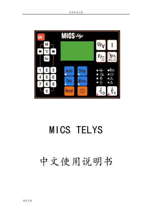
中文使用说明书目录1.前言1.1安全事项1.2电源连接1.3电气连接(控制)1.4电池预检查和试运行1.5MICS Telys 第一次加电1.6欢迎界面1.7“纵览”界面2.工作模式2.1停机模式2.2编程模式2.3自动模式2.4测试模式3.休眠模式及自动断电3.1休眠模式3.2自动断电4.察看电气指标。
4.1电压4.2电流4.3频率和累计时间5.察看发动机参数6.显示LEDs及灯测试7.屏幕对比度8.显示警报和故障信息8.1屏幕信息8.2清除屏幕信息9.状态信息的显示10.进入一级菜单11“告警/故障”菜单11.1故障特性11.2告警特性11.3其他的特别情况12.“状态”菜单13.“输入”菜单14.“输出”菜单15.“对比度”菜单16.“保护”菜单16.1活动保护16.2通过CIC的保护16.3特别情况17.发电机组的操作17.1水加热器17.2发动机预热17.3油阀控制17.4启动马达控制17.5启动马达的脱离17.6转速和电压稳定17.7发电机组的输出17.8发动机冷机和关机18.ATS的操作18.1停机模式18.2自动模式18.3手动模式1、机油压力故障/停机(红灯亮)2、水温故障/停机(红灯亮)3、过载故障/停机(红灯亮)4、超速故障/停机(红灯亮)5、发电机组带载或准备带载(绿灯亮)6、充电电机报警停机(红灯亮)7、一般报警(黄灯闪烁)8、一般故障/停机(红灯闪烁)自动关闭之后重新开启按钮主菜单按钮确认按钮退出按钮浏览选择按钮及灰度调节数字键盘断开发电机组断路器闭合发电机组断路器电压显示按钮电流显示按钮频率及小时计按钮显示发动机参数按钮自动模式按钮(灯亮)测试模式按钮(灯亮)停止模式按钮(灯亮)手动模式按钮(灯亮)故障复位按钮灯光测试按钮(不包括ON按钮的灯)1.机油压力故障/停机(红灯亮)2.水温故障/停机(红灯亮)3.启动失败故障/停机(红灯亮)4.超速故障/停机(红灯亮)5.发电机组带载或准备带载(绿灯亮)6.充电发电机告警停机(红灯亮)7.综合告警(黄灯闪烁)8.综合故障/停机(红灯闪烁)四、1、前言1、1概述MICS Telys连接到不同交流电压源。
东方电机C-266型号步进电机系统配置2003 2004年版说明书

RS232C-Compatible ControllerSC8800/SC8800E for Stepping Motor SystemsⅥFeaturesⅷEasy-to-Use●The instruction set software is built into the controller. There is no need for set-up diskettes.●Can be pre-programmed prior to installation.●An easy-to-learn instruction set allows for complete system operation.●End-of-travel and home positions can be easily determined by the three dedicated limit switch inputs.●Operates on 10 to 28 VDC so the controller can be powered by a standard power supply.ⅷProgramming Options●Can be controlled or programmed directly from a computer or ASCll terminal via a standard RS-232C port.●Can be controlled by industry-standard programmable logic controllers so it can run off any already existing PLC.●Linear, S-curve and parabolic acceleration/deceleration profiles are available. ⅷFlexible I/O●There are four programmable inputs and two programmable outputs to give the controller the ability to control other functions within the machine. All inputs and outputs are optically isolated.●Step and direction signal outputs are industry standard TTL level signals in either 1-pulse or 2-pulse modes so the SC8800and the SC8800E can be used with any industry-standard stepping motor and driver package.●All I/Os can be driven by an external DC power supply of 5 to 24 VDC.ⅷEncoder Feedback Capabilities (Model SC8800E)●Nearly every known feedback device can be recognized since the controller can use two or three channels in either single-ended or differential modes.Daisy-Chain Capabilities●Up to 35 different axes can be controlled from one computer or ASCII terminal by daisy-chaining up to 35SC8800or SC8800E controllers together.●Available with an optional encoder input for position verification (model SC8800E).The SC8800and SC8800E controllers can beprogrammed from a computer or ASCII terminal via astandard RS-232C port.ⅥSystem ConfigurationEncoder Feedback (modelController DriverC-266ORIENTAL MOTOR GENERAL CATALOG 2003/2004System Configuration C-266Features C-266ORIENTAL MOTOR GENERAL CATALOG 2003/2004C-267Specifications C-267Dimensions C-269C-268ORIENTAL MOTOR GENERAL CATALOG 2003/2004System Configuration C-266Features C-266Outputs 1 & 3 “ON”StartV e l o c i t y V (H z )The two moves shown above can be executed with the following program commands :Commands 1LOOP 102SAS Push START to begin 3VS700; V15004TA1; TD1.55PC0; EC06H ϩ7D65008MI9DELAY110IF (CP!ϭ0)11THEN JMP112ELSE DELAY313OUT ϭ10114V200015T416WHILE (IN1ϭ0)17MC 18ENDW 19V2500; MC 20DELAY521V120022DELAY223STOP 24ENDL DescriptionLoop this program 10 times Echo message to screenSet start and run velocities for the first move Set Accel time to 1 sec & Decel time to 1.5 secSet position and encoder counters to zero Set direction to CWSet distance to 6500 steps Execute the Index move Delay 1 secondIf encoder position is incorrect,Then, restart program Else Delay 3 seconds.T urn on Outputs 1 and 3Set velocity to 2000 steps/secSet Accel & Decel time to 4 sec. for second move While Input #1 is off,Move continuously End the while loopChange speed to 2500 steps/sec Delay 5 secondsChange speed to 1200 step/sec Delay 2 seconds Stop movingReturn to beginning of loopWhen start signal is input, program beginsⅥProgramming ExampleORIENTAL MOTOR GENERAL CATALOG 2003/2004C-269Dimensions C-269ⅥDimensions Scale 1/4, Unit = inch (mm)SC8800SC8800EWeight: 0.68 lb. (0.31 kg)ⅥSystem LayoutDriverMotorPowerSource。