1-introduction
TOPIC_1_-_INTRODUCTION_TO_OPERATIONS_AND_SERVICES

Outputs
Operational Strategies:
Employee Performance – six sigma, quality circle, etc Productivity improvement strategies Production system: MRPII, WCM, JIT, six sigma, etc Quality – ISO, TQM
• Hot yet quality food • Satisfied customers resulting in profits Challenge: Finding the most suitable system of food preparation to meet the objectives as stated above. Dissatisfaction could be due to poor quality, e.g., too spicy, too cold, etc
13
Joseph M. Juran Armand V. Feigenbaum Philip B. Crosby Kaoru Ishikawa Genichi Taguchi
Old vs. New Concepts of Quality
Time Early 1900s 1940s 1960s 1980s and beyond
3
System Approach as an Open System:
External Forces: PESTDC
INPUT
TRANSFORMATION PROCESS
OUTPUT
FEEDBACK LOOP
4
Transformation Process:
[英语学习]unit-1-Introduction
![[英语学习]unit-1-Introduction](https://img.taocdn.com/s3/m/c54459bff7ec4afe05a1df71.png)
展。
• a Panorama of Publishing 出版业概况 • book industry 图书出版业 • book community 书业团体
Questions on part 1
• 1 [+ obj] : to prepare and produce (a book, magazine, etc.) for sale ▪ It's a small company that only publishes about four books a year. ▪ The university press publishes academic titles. ▪ The newspaper is published daily. 2 : to have something you wrote included in a book, magazine, newspaper, etc. [no obj] ▪ There is a lot of pressure for professors to publish regularly. [+ obj] ▪ He has not published anything for a long time. 3 [+ obj] : to include (an article, letter, photograph, etc.) in a magazine or newspaper ▪ The magazine published two of my stories.
3. intriguing
1.Introduction

特殊光学显微镜技术
暗视野显微镜 偏光显微镜 倒置显微镜 相位差显微镜 荧光显微镜 激光共聚焦显微镜
荧光显微镜
激光扫描共聚焦显微镜
laser scanning confocal microscope, LSCMope, EM)技术 )
苏木精( 苏木精(Hematoxylin)+ 伊红(Eosin)染色 ) 伊红( ) 碱性染料 将嗜碱性物质( 将嗜碱性物质(本身 酸性) 酸性)染成紫蓝色 细胞核中的DNA、RNA 、 细胞核中的 细胞质中的 细胞质中的RNA 酸性染料 将嗜酸性物质( 将嗜酸性物质(本身 碱性) 碱性)染成粉红色 细胞质、膜性结构 细胞质、 线粒体、溶酶体、 (线粒体、溶酶体、 滑面内质网) 滑面内质网)
细胞化学和组织化学
如: 检测多糖:过碘酸雪夫反应 检测多糖:过碘酸雪夫反应(periodic acid Schiff reaction):简称 PAS反应。 反应。 : 反应 检测脂类 :苏丹III染色法 苏丹III染色法 III
反应) 过碘酸雪夫反应 (PAS反应 反应
脂类组织化学染色(苏丹 染色) 苏丹III染色
一般光学显微镜技术(light microscope, LM) )
石蜡切片、冷冻切片、涂片、舖片、磨片
一般光学显微镜技术
最常用的是石蜡切片,HE染色 切片的制作步骤: 固定(fixation) 包埋 (embedding) 切片 (section) 染色(staining)
HE染色: 染色: 染色
核酸分子原位杂交术
是利用标记的特 异性DNA、RNA或 寡核苷酸探针检 测细胞内某种基 因片断的方法
组织学实验技术的作用
组织学实验技术是现代生物医学领域 诸多基础及前沿学科学习和研究的重 要技术支持。
Lecture 1-Introduction

Imaging in the Visible and Infrared Bands
Sources of Images
Imaging in the Visible and Infrared Bands
Sources of Images
Imaging in the Visible and Infrared Bands
• •
Human Vision System Mathematicians
•
Prior Knowledge Image models Transformations Methodologies
Impacts?
• • •
Categorization – My Viewpoint
•
Image Processing Methodologies
About This Course
Resources?
Scoring policy
Presence – 15% Final exam – 85%
Course Outline
32 hours = 3×10 lectures + 2 for course review Lecture 1 – Introduction Lecture 2 – Digital Image Fundamentals Lecture 3 – Image Transformations Lecture 4 – Image Enhancement Lecture 5 – Image Restorations Lecture 6 – Color Image Processing Lecture 7 – Image Compression Morphological Image Processing Lecture 8 – Image Segmentation Lecture 9 – Representation and Description Lecture 10 – Image Recognition
unit_1_introduction[1]
![unit_1_introduction[1]](https://img.taocdn.com/s3/m/5a44843a10661ed9ad51f372.png)
1.1 Text(2)
• According to the information direction transmitted in channel, modern communication systems can be divided into the simplex communication systems, half-duplex communication systems, and full-duplex communication systems; • According to the number of information communicating approaches, modern communication systems can be divided into the serial communication systems and the parallel communication systems; • According to the control methods of information transmitted in channels, modern communication systems can be divided into the synchronous communication systems and the asynchronous communication systems; • According to the line connecting modes and signal interacting ways between signal source and destination, modern systems can be divided into point-to-point communication systems, one-to-multi-points communication systems and multi-to-multi-points communication systems.
Chapter1-Introduction

共56页
9
信息和知识隐藏在数据中
商务智能要求有一个坚固、可靠的大型数据库作后盾,建立这样一个数据库的任 务是极其艰巨的。数据的质量问题也是令人头疼而又不可以掉以轻心的。 虽然数据是宝贵的财富,然而许多公司并不能充分利用这种财富,因为信息隐藏 在数据中,并不易识别。 为了在竞争中占得优势地位,必须识别和应用隐藏在所收集的数据中的信息。
共56页
15
信息流畅通了还需要?
商务智能BI(business intelligence)
SCM
供应链 管理
ERP
企业资源规划系统
B2B、B2C
CRM
数据
Internet等基础设施
共56页
16
新一代决策支持系统
交易处 理系统 DSS 资料库 外部资料
DSS软件系统模式 OLAP工具 资料挖掘工具 使用者界面
目标市场 资金分配 贸易选择 在哪儿做广告 销售的地理位置
数据爆炸,知识贫乏
共56页 14
Do You Trust Your Information?
Up to 75% have made business decisions that later turned out to be wrong due to flawed data
2
概念解析
何谓智能?企业有智能吗? 智能的表现
信息共享和企业信息集成 知识挖掘与管理
1Introduction
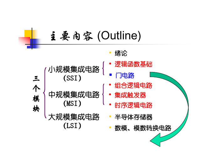
主要内容 (Outline)• 绪论小规模集成电路三(SSI)• 逻辑函数基础 门电路个• 组合逻辑电路模 块中规模集成电路 (MSI)• 集成触发器 • 时序逻辑电路大规模集成电路 • 半导体存储器(LSI)• 数模、模数转换电路绪论 (Introduction)一、数字(digital)信号和模拟(analog)信号 数字量和模拟量 数字电路和模拟电路二、数字信号相关概念 二进制数 Binary Digits 数字信号的逻辑电平 Logic Levels 数字信号波形 Digital Waveforms一、Digital Signal and Analog Signal Digital and Analog Quantities电子 电路 中的 信号模拟信号: 连续analogue signal value数字信号: 离散digital signal valuetime time模拟信号T( C) 30采样信号T( C)sampled3025离散化 2520202 4 6 8 10 12 2 4 6 8 10 12 t (h)A.M.P.M.2 4 6 8 10 12 2 4 6 8 10 12 t (h)A.M.P.M.数字化-表示 为由0、1组成 的二进制码Analog Electronic SystemDigital and Analog Electronic System★ 工作在模拟信号下的电子电路是模拟电路。
研究模拟电路时,注重电路输入、输出信号 间的大小、相位关系。
包括交直流放大器、 滤波器、信号发生器等。
★ 模拟电路中,晶体管一般工作在放大状态。
★ 工作在数字信号下的电子电路是数字电路。
研究数字电路时,注重电路输出、输入间的逻 辑关系。
主要的分析工具是逻辑代数,电路的 功能用真值表、逻辑表达式或波形图表示。
★ 在数字电路中,三极管工作在开关状态, 即工作在饱和状态或截止状态。
#slang 1 - introduction
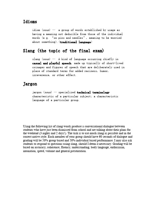
Idiomsidiom (noun) — a group of words established by usage ashaving a meaning not deducible from those of the individualwords (e.g. “on pins and needles”, meaning to be worriedabout something).(traditional language)Slang (the topic of the final exam)slang (noun) — A kind of language occurring chiefly incasual and playful speech, made up typically of short-livedcoinages and figures of speech that are deliberately used inplace of standard terms for added raciness, humor,irreverence, or other effect.Jargonjargon (noun) — specialized technical terminologycharacteristic of a particular subject; a characteristiclanguage of a particular group.Using the following list of slang words produce a conversational dialogue between students who have just been dismissed from school and are talking about their plans for the weekend (3 nights and 2 days!). The task is to use much slang as possible and in the correct native style. Each member of your group should have 60 seconds of dialogue and grading will be 50% group based and 50% individual based performance. I may also ask students to respond to questions using slang, should I deem it necessary. Grading will be based on accuracy, coherence, fluency, understanding, body language, enthusiasm, intonation, speed, volume and general presentation.。
- 1、下载文档前请自行甄别文档内容的完整性,平台不提供额外的编辑、内容补充、找答案等附加服务。
- 2、"仅部分预览"的文档,不可在线预览部分如存在完整性等问题,可反馈申请退款(可完整预览的文档不适用该条件!)。
- 3、如文档侵犯您的权益,请联系客服反馈,我们会尽快为您处理(人工客服工作时间:9:00-18:30)。
1Introduction1.1Motivation and Structure of the BookA variety of on-going research is focused on the development and analysis of methods to decrease the time required to progress from the computer modeling of the design surface to the machining while maintaining or improving the quality of the surface.One of the most important areas is tool path planning for numerical control(NC)machining.The main goal is obtaining the cutter location and orientation data that allow for an efficient surface milling within an allowed machining error.Five-axis NC machines are becoming increasingly popular due to their ability to handle geometrically complex workpieces composed of raw material such as wood,wax,rubber,metal,stone,plastic,etc.Moreover,up-to-date five-axis NC machines are characterized by a high material removal rate and an efficient surfacefinish up.Typically,manufacturing of the design surface by an NC machine com-prises two stages,a rough cutting and afinish machining.During the rough cutting,the raw material is removed as fast as possible while ensuring no ex-cessive cutting or gouging.During thefinish machining,the tool is placed at the maximum contact with the surface to remove the remaining excess and create a well-finished and accurate surface.Afterfinishing,the remaining scal-lops which are inevitably generated on the machined surface must be removed by manual surface grinding and polishing.Thefinish machining and manual polishing stages require as much as75%of the total machining time.Besides, manual polishing is prone to error and undesirable irregularities.Five-axis machining offers an improvement in efficiency of both the rough andfinish machining stages over the three-axis counterpart.Infive-axis ma-chining,the tool orientation relative to the workpiece can be controlled by two additional degrees of freedom so as to achieve higher machining efficiency. With these advantages,a large number of tool path planning methods for five-axis machining has been developed and presented in the literature.21IntroductionIn chapter1we present the most popular CAD/CAM data formats and give a short literature survey on mathematical methods for optimization of five-axis machining.The survey has been focused on tool path interpolators, adaptable geometric patterns and methods for tool posture and gouging avoid-ance.Chapter2exposes the readers to basic knowledge required to perform five-axis cutting.The G-code programming,examples offive-axis machining of simple shapes and verification of the cut using solid modeling software is presented and discussed.The chapter can be used as a short introduction into five-axis machining in the framework of an undergraduate course in Computer Aided Design(CAD)and Computer Aided Manufacturing(CAM).Chapter3introduces theories required to embrace the concepts of the tool path optimization forfive-axis machining.The chapter presents such funda-mental issues as kinematics of thefive-axis machines,part surface represen-tation,machining strip,tool orientation and gouging avoidance as well as the forward step error.A variety of configurations of thefive-axis machines is also discussed and analyzed.This chapter can also be used at an undergraduate or a postgraduate level for CAD/CAM related studies.Chapters4and5present advanced optimization schemes based on the adaptable geometric patterns,namely,the space-filling curves(SFC)and adaptive curvilinear grids.The SFC tool path has a number of attractive features such as the possibility to locally adapt the curve in such a way that the cutting device travels along the optimal direction.In addition,the entire surface is cut in one path eliminating the need of tool retractions.The use of the concept of curvilinear grids allows to simultaneously adapt the points on the tool paths to create more efficient zigzag,spiral or even SFC structures. The combination of the SFC and grid generation allows for tool paths on surfaces with complex irregular boundaries,cuts off,pockets,islands,etc.Three-axis machines are often thought of as three dimensional plotters. However thefive-axis machine is more like a big bore machine.That is why changing from three-axis tofive-axis programming is not an easy task.In particular,the idea of optimizing rotations may seem totally foreign from the viewpoint of the three-axis machining.Therefore,chapter6presents the the-ory and practice of optimization of rotations forfive-axis machining.Several optimization algorithms based on the shortest path techniques are presented and discussed.Chapter7presents a theoretical background developed to construct nu-merical algorithms to minimize kinematics error introduced by the initial setup offive-axis milling machines.The initial setup consists of the posi-tion and orientation of the workpiece with respect to the mounting table and, optionally,the machine’s initial configuration.Given a set of cutter contact points and tool orientations,a least-squares optimization procedurefinds the optimal setup parameters.1.2CAD/CAM Formats3 1.2CAD/CAM FormatsSculptured or free-form surfaces are widely used in today’s manufacturing industries for a variety of applications such as the production of dies,molds, aerospace and automotive parts,etc.The surfaces are usually characterized by complex geometries and variable curvatures.A single surface is usually composed of patches represented mathematically by parametric forms such as the Bezier surfaces,B-splines and NURBS.A design and manufacture of the sculptured surface parts is an expensive and time-consuming process.First,a design surface is transformed into a computer model(possibly with the help of CAD programs).The computer model is then used by the CAM programs to generate commands to move the cutting tool of the machine.The resulting set of tool positions and orientations constitutes a tool path to machine the desired surface.Every CAD or CAD/CAM software uses an internal format to represent and control the required part.When the geometrical data is transferred from a CAD system to a CAD or CAM system,a neutral format for the data transfer is used.One of the most popular is the IGES(Initial Graphics Exchange Specification)format(see the history of the IGES format in[40]).The IGES format supports the use of surfaces defined by NURBS(Non Uniform Rational B-Splines)or derivatives of these representation.A good book for a beginner in NURBS is[31].An advanced reader could use[98]and[24].There are also several free libraries designed to control and manipulate the NURBS, such as NURBS++package[1]and NURBS Toolbox[2].Some free IGES-file processing tools are collected at the NIST/IGES web page[3].The STLfiles,originally employed by the so-called layered manufacturing technologies such as the rapid prototyping,are now becoming more and more popular due to the simplicity of describing the part surfaces.As opposed to the complex description of surfaces employed by the IGES format,the STL format defines the surface as a collection of triangles each described by the coordinates of its three corners and a normal-vector.This technology provides an important platform for CAD/CAM applications due to the existence of many robust triangulation algorithms.Besides,the surface models are often composed of many patches.Therefore,by tessellating the patches and creating groups of triangles one can use many well established methods for treating intersections,trimming,shading,hidden surface removal and gouge protection [36].The machining is usually performed by creating contours obtained by slicing the STL-surface[85,115].Of course,slicing of the NURBS surfaces is also possible,but it requires much more sophisticated techniques such as[81]. The contours are then saved using the SLC format(see[4]for instance).Other popular CAD/CAM formats include STEP(Standard for the Ex-change of Product Data),DXF(The Drawing Exchange Format from Au-toDesk)and many others.As a matter of fact,the difference in data formats has created a large software industry specializing in transferring,adapting and41Introductionprocessing the CAD/CAMfiles.A table of compatibility of the CAD/CAM formats can be found,for instance,at[5]or[6].1.3Short Literature SurveyOptimization of tool paths forfive-axis machining may include many features and multiple criteria such as the accuracy,the length of the tool path,the machining time,the size of the remaining scallops,etc.It may also include gouging avoidance,satisfying the machine axis limits,maximizing the volume of the removed material,reducing the tool wear.The optimization may also take into account the thermal characteristics of the cutting process,the tool bending,the vibrations and jacks,the workpiece positioning and many other parameters.The criteria could also include the configuration of the machine or specific parts of the machine as well as the design of the clamping device. Readers interested in citations before1997could use a fairly comprehensive survey by Dragomatz and Mann[25].The survey presents a classification of research papers on three-axis andfive-axis machining related to geometries of the tool paths and tool positioning.These categories include:1)systems,2) isoparametric paths,3)non-isoparametric paths,4)planar pocketing paths, 5)sculptured surface pocketing paths,6)roughing paths,7)tool position-ing,8)offset surface methods,9)five-axis machining,10)mesh models,11) pixel and point models,12)simulation and verification.Of course,the above groups overlap.Techniques involved in one group could be also involved in another group.For example,systems for tool path generation may include all of the above mentioned techniques.Roughing paths may be generated by the isoparametric or non-isoparametric schemes and so on.Our survey is focused onfive-axis machining.It also includes the three-axis methods but as long as they can be extended to thefive-axis case.Besides, we confine ourselves by techniques designed for cutting the part surface by bottom-edge of the tool,e.g.,flat-end milling andfillet milling.Many interest-ing methods designed forfive-axis grinding(flank milling)and plunge milling have not been included.The survey has been focused on the following categories:1)tool path in-terpolators,2)adaptable geometric patterns and3)methods for tool posture and gouging avoidance.We believe that the above procedures are the most important part for efficient design of the numerical methods forfive-axis ma-chining.Tool path interpolatorsIn the CNC machines,the tool motion is controlled by a sequence of reference points that are fed to the servo control system.The NC controllers employ linear interpolation techniques[66]or a circular interpolation which may result in discontinuities of the velocity at the junctions of the segments.They may1.3Short Literature Survey5 also result in high accelerations,subsequent surface inaccuracies and long machining time required to eliminate them.Furthermore,the modern high speed machining requires feedrates up to40m/min with accelerations up to 2g.At such high speeds,small discontinuities in the reference tool path can result in undesirable high frequency harmonics in the reference trajectory, which may end up exciting the natural modes of the mechanical structure and the servo control system.Although the NC program cannot change the way the controller moves the machine parts,the cutter location points and the rotation angles required to cut the prescribed curve can be changed in such a way that these errors are minimized or at least decreased.The task of generating such a sequence of points is called interpolation.Early interpolation schemes solved the problem of discontinuities by smoothing the tool path at the corners[17]and using low passfilters[126].However,the problem is due to the difference between the chord and the arc lengths.That is why,generating the tool positions by incrementing the chord length leads to the feedrate instabilities.Therefore, if thefit curve is parameterized with respect to the arc length,these type of the inaccuracies will be eliminated.Therefore,many modern interpolation schemes are focused onfinding a suitable polynomial interpolation(such as the B-splines)parameterized by means of the arc length.Unfortunately,such parameterization is not analytically possible for gen-eral spline curves.Therefore,a number of approximate solutions were pro-posed.For instance,Wang and Yang[122]generate the trajectory by means of cubic and quintic splines using the chord length and a nearly arc length parameterization,Zhang and Greenway[133]implemented a similar B-spline based interpolation.Coordinate transformations between the workpiece and machine coordinate systems forfive-axis milling were incorporated in the inter-polator by Lo[77,79]and Bohez et al.[14].An extra jerk continuity condition has been included into the solution in[121].Furthermore,the limitations of the machine tool drivers may cause fail-ure in maintaining the commanded feedrate which in turn may lead to the tool chatter or breakage.Therefore,Weck et al.[125]have implemented cubic spline interpolation where adaptation of the feedrate was based on the physical limitations of the drives.The smooth transitions were obtained using fourth order acceleration profiles.Erkorkmaz and Altintas[30]presented a quintic spline trajectory generation algorithm that produced continuous position,ve-locity,and acceleration profiles.Smooth accelerations and decelerations were provided by imposing constrains on thefirst and second time derivatives of the feedrate.In1994,Farouki and Sakkalis[33]introduced the Pythagorean-Hodograph (PH)curves to solve the problem of feedrate control for three-axis machines. The curves provide a mathematically elegant solution to the above mentioned problems occurring in NC machining.In particular,the arc length was repre-sented by a polynomial function of the curve parameter.In[32],a2D Hermite interpolation combined with the PH was proposed and analyzed.The ideas61Introductionwere further developed in[34,35].It was shown that since the arc length of the PH curves can be represented by a polynomial function of the curve parameter,they can be successfully used for the interpolation.Consequently, a variety of planar PH curves matching given Hermite type boundary data were developed(see,for instance,[61,88,119]).M¨u ller et al.[90]presented an algorithm for simultaneousfive-axis spline interpolation which merges the PH interpolation and the analytic solution of the inverse kinematics problem using the template equation method.The result is a time-dependent spline which represents the given tool path with a high ngeron et al.[69]suggested a polynomial B-spline interpo-lation which took into account the kinematics of thefive-axis machine.The B-spline interpolation of the tool path in the part coordinate system includes the accuracy requirements and describes afive-axis tool path in a format adapted to the communication between the CAM software and the NC unit. The CAM output is directly expressed through the B-spline curves.Lo[80] introduced spline interpolators for isoparametric,iso-scallop and iso-planar machining methods(see the forthcoming section).ˇS´ır et al.[118]presented biarc interpolation techniques based on spline curves composed of circular arcs and compared them with the PH curves.Finally,a number of papers introduce interpolators designed for high speed milling.During the high speed machining the actual average feedrate could be significantly lower than the programmed feedrate due to the physical restric-tions of the machine tool and the block processing time of the CNC controller. In many cases the machine tool hardly reaches the maximum feedrates offered by the manufacturer.This happens when the block processing time is longer than the block execution time and the machine reaches the end point of the segment before information required for the next movement is available.In this case modern CNCs automatically reduce the programmed feedrate which results in a lower real feedrate and,consequently,a longer machining time. This relatively new issue has been discussed in[55,64,87,109].Adaptable geometric patternsThis section surveys research aimed to construct geometric patterns adaptable to a criteria which represents a certain estimate of the quality of the tool path such as the kinematics error,scallop heights,undercuts,overcuts,etc.It also includes methods for complex pocket milling since they often require special geometric patterns.Finally,the construction of the geometric patterns might or might not take into account the actual machine kinematics.In many cases, patterns employed for three-axis machining are also applicable,with certain modifications,to thefive-axis machining.The simplest tool path planning algorithms employ structured zigzag or spiral patterns due to their simplicity and the ease of computation(see [25,108]).The zigzag and spiral motions employ uniform steps along a coor-dinate which parametrizes the desired curve extracted from the part surface.1.3Short Literature Survey7 The early adaptable methods replace the uniform spacing in favor of distrib-uting the cutter location points by analogy with interpolation characterized by a variable step.First,the trajectories were assumed to be linear.Next,the desired curve was approximated using a certain technique,for example,em-ploying arcs.Next,the forward step was selected by considering the deviation between the approximation and the straight line(see,for instance,[73]).The choice of the forward step can be performed by bisection or another inexpen-sive method.Some of the recent developments of these ideas are presented in [22,73].As mentioned before the most popular geometric solutions are the zigzag and the spiral isoparametric patterns constructed for single-patch or multi-patch parametric surfaces S(u,v).In this context,the term isoparametric means that the zigzag tool path is generated in the parametric space u−v along one of the coordinates,say,u.The v coordinate is then used to generate the forward steps.Another approach is the contour based or iso-planar machining.In this case the cutter path follows intersection curves of the parametric surface anda series of vertical planes.One of thefirst papers reporting such techniques is[19],see also[104].The both methods calculate the maximum allowable distance between the consecutive tracks using a scallop height limitation.However,if the maximum allowable distance is calculated globally,that is,the minimal allowable dis-tance is taken from all the maximum allowable(pointwise)distances,then the method does not produce a constant scallop height.As the result,the ma-chining efficiency is limited.Methods to maintain the constant scallop height called the iso-scallop machining methods werefirst proposed in[76,112].Lo[78]developed these approach and adapted it tofive-axis machining. His algorithm starts with an initial curve in the parametric domain and calcu-lates offset curves so that the scallop height remains approximately constant. The algorithm is designed forflat-end cuter and includes adaptive inclina-tion which maximizes the machining strip.The algorithm also includes a local gouging avoidance.The local gouging refers to the removal of an excess mater-ial in the vicinity of the cutter contact point(CC point)due to the mismatch in curvatures between the tool as it is carried along the tool path and the desired surface(see the forthcoming section for details).Rao and Sarma[103] introduced similar local gouging avoidance algorithms applicable to surfaces characterized by low curvature and cut by theflat-end cutter.Finally,Lo[80] presents an iso-scallop tool path for ball nose cutters.Evaluation of the machining strip versus the inclination and the direction could lead to complicated tool path topologies.For each tool position on the surface there exists at least one direction which maximizes the machining strip. The corresponding set of vectors mapped onto the parametric space(u,v) constitutes a2D vectorfield which could be further analyzed.A continuous tool path which visits every point and follows the optimal direction at every point constitutes the optimal tool path which will maximize the machining81Introductionstrip globally.However,such a path can rarely be found in practice due to the complexity of the resulting vectorfield.An algorithm tofind a suboptimal solution of this problem is presented in[20].The authors introduce an“initial”tool path which has the largest average machining strip.Next,the entire tool path is constructed by propagating the initial path inside the region until it substantially deviates from the streamlines.A few papers explore other“iso”methods such as the iso-distance and the iso-curvature methods(see,for instance,[47]).In[63]an additional tool path segments are appended to the basic tool path in order to achieve constant cutting forces and to avoid chatter vibrations in the entire machining area. Furthermore,the necessity to create geometric patterns suitable for the so-called pocket milling leaded to a series of methods designed for parts with one or more complex shaped“islands”inside.The methods are also needed to machined the so-called trimmed surfaces when the boundaries of the surface are defined by intersections with other surfaces.In1998,Choi and Jerard[21]introduced a term regional milling referring to situations when the machining operation,occurs in a region specified by boundary curves.According to[96]the regional milling can be performed using the same types of tool path topologies,namely,the contour-based offset type and the direction-parallel type.The direction-parallel type has been analyzed in[45,46,49],whereas the direction-parallel type in[21,48,51,94].One of the most important problems in the contour-based machining is linking the contours in such a way that the number of tool retractions is minimized.Held et al.[51]presents an algorithm designed for this type of machining based on the proximity maps and the Voronoi diagrams.The au-thor suggests a linking procedure requiring a spanning tree of the planar graph of the monotonic pouches.Park and Chung[95]propose a contour linking al-gorithm accommodating minimization of slotting,tool-retractions and drilling holes.Park et al.[96]presented a tool path linking algorithm,which guaran-tees a“zero”number of tool-retractions.The algorithm employs the concept of tool path element net providing information on the parent/child relation-ships.Jeong and Kim[57]present an algorithm designed to offset the bound-ary curves in the complex shaped region using the Voronoi diagram.Each curve segment is offset within the corresponding Voronoi polygon to avoid the degeneracy problem.Jeong and Kim[58]introduce a distance map algorithm which effectivelyfinds the characteristic points and self intersection points of the offset curve segments and as the result eliminates such topological prob-lems as loops,ridges and cusps.A forward locus tracing method is introduced in[68].The algorithm searches for all intervals split by intersections of the planar curves and maps the2D transversal intersections onto a1D interval.Suppose that the part is partitioned into a grid of cells each of them being a curvilinear triangle or a curvilinear rectangle.The optimization can then be considered as constructing a path which visits each cell,does not have intersections,requires minimal number of tool retractions and satisfies1.3Short Literature Survey9 some error related criteria.Pocket machining using staircase or window frame patterns were proposed in[97].Hansen and Arbab[46]developed a scan line algorithm for generating NC tool paths for arbitrarily shapedflat bottom pockets with islands.Flat pocket machining based on grids was suggested by Bao and Yim[11].Treating the tool path generation as a navigation problem on grids leaded to approaches exploiting the shortest path optimization and related tech-niques.Suh and Shin[110]developed a neural network model to obtain the tool path in rough pocket machining as a solution to the traveling salesman problem.A good mathematical analysis of such strategies is given in[9].The problem is formulated as follows:given a region in the parametric plane and the shape of a cutterfind a shortest tour/path for the cutter such that every point within the region is covered by the cutter at some position along the tour(tool path).Additionally the cutter could be constrained to stay within a certain region.Narayanaswami and Choi[91]present a grid-based3D naviga-tion approach for generating NC tool path data for both linear interpolation and a combination of linear and circular interpolation for three-axis milling. The approach can be extended to thefive-axis case.The space-filling curves(SFC),having been applied in computer graphics, image processing,information systems,can be also seen as a suitable naviga-tion pattern for generation offive-axis paths.Thefirst application of the SFC to NC tool path generation was reported in[23,44].Griffiths[44]proposed the use of the Hilbert’s curve as a tool path,while Cox et al.[23]used various forms of space-filling curves such as Moore’s curve.Fractal based techniques were suggested by Chen et al.[18].However,neither SFCs nor fractals have never been very popular in the five-axis machining community due to a large number of sharp turns produced by the conventional SFCs.A concept of an adaptive space-filling curve for tool path planning forfive-axis NC machining was proposed in[8].The space-filling curves,adapted to the local optimal cutting direction,produce shorter tool paths.Besides,the tool path correction stage suggested in[8]makes it possible to eliminate the effect of sharp angular turns which characterize the standard SFC patterns.These techniques will be presented in Chap.4of this book.Finally,the entire tool path can be considered in the framework of the grid generation technologies.The concept wasfirst introduced by Makhanov [82]and developed in[15,83].The grid generation techniques are surprisingly well-adapted to tool path optimizations.As a matter of fact,the concept of a grid refinement contains almost all the main ingredients for tool path plan-ning,such as grid adaptation to the regions of large milling errors,possibility to easily construct curvilinear versions of the conventional zigzag and spiral patterns and adaptation to constraints related to the tool diameter and the scallop height.Moreover,in contrast to the standard techniques characterized by a local error estimate,grid generation deals with a global spatial error and consequently adapts all the CL points simultaneously.These ideas were de-veloped further in[84],specifically forfive-axis machining whereas Bieterman101Introductionand Sandstrom[12]suggested a similar approach,independently.Finally,Sun et al.[111]presented a spiral version of the grid generation algorithm applied to tool path generation.The advanced grid generation techniques forfive-axis machining will be considered in Chap.5of this book.Tool posture and gouging avoidanceThis section deals with techniques providing an optimal position and orien-tation of the tool in a particular neighborhood of the machined surface.The emphasis is on the orientations prescribed independently with regard to a certain criteria such as the local gouging avoidance,machining strip,scallop height,avoiding global gouging constraints,etc.The most important appli-cation of these techniques is cutting the part surface by theflat-end orfillet mill.In1987,Marciniak[86]showed that infive-axis machining the maximum width of machined strip on the surface could be obtained if the tool moved on the surface approximately along the minimum curvature line.The maximum width of the strip depends on the difference of the surface main curvatures at the contact point.Some of the early research papers exploiting this idea are[37,67,74].Furthermore,Kruth and Klewais[67]introduced an optimal milling direction parallel to the principal direction of the surface with the minimum curvature.Gani et al.[37]notice that“One of the critical problems infive-axis milling is the positioning of the cutter in relation to the surfaces in order to machine without having overcut(gouging)or undercut.Because of this problem,ball-end cutters are preferred.Undercutting does not cause a big problem when using ball-end cutters.The calculation of the NC tool path for ball-end cutters is mainly a problem of surface offset.An important drawback of ball-end cutters is the varying cutting speed along the tool radius.The maximal cutting speed is reached on the tool diameter,and at the tool tip it is zero.This leads to cutting edge chipping as well as poor surface roughness”.Recall that as long as thefive-axis machines are considered,the tool has five degrees of freedom relative to the surface.The three spatial degrees are used to locate the tool at the cutter location points point.The extra two ro-tational degrees are used to establish the orientation of the tool represented by the inclination angle and the tilt angle(see,for instance,[103])or the tilt angle and the yaw angle[60].The angles are evaluated in a local coordinate system usually defined by the feed direction,the surface normal and the cor-responding cross product vector.In the case of theflat-end mill the boundary of the base of the tool,which is the part of the tool cylinder is called the cutting circle of the tool.The effective cutting shape(also referred to as the tool swept section)is defined as a projection of the base of the tool onto the plane normal to the feed direction.Actually,in the case offlat-end mill the projected bottom edge becomes an ellipse called the effective cutting ellipse.。
