惯性导航,捷联惯导 外国论文
《惯性导航系统范文合集》
《惯性导航系统范文合集》第一篇:惯性导航系统惯性导航系统(inertialnavigationsystem,ins)惯性导航系统(ins)是一种不依赖于外部信息、也不向外部辐射能量的自主式导航系统insisanautonomousnavigationsystem,relyingontheoutsideinformation,notradiatingenergy,noteasilydisturbedbyenemy.抗干扰能力强stronganti-interferenceability精确性好,goodaccuracy长期精度差accuracyforlongtimework价格昂贵expensivestep1:傅科(leonfoucault)提出陀螺的定义、原理及应用设想themeaningandapplicationofgyroscope(byleonfoucault).第一代惯性技术奠定了整个惯性导航发展的基础step2开始于上世纪40年代火箭发展的初期beginfromtherocket’sdevelopment惯性传感器inertialsensor,(accelerometer加速度计)提高ins的性能,improveins’performance.静电陀螺(esg)、electrostaticsuspensiongyroscope动力调谐陀螺(dtg)dynamicallytunedgyroscope环形激光陀螺(rlg)、干涉式光纤陀螺ifog等高精度、高可靠性highaccuracy,highstable,小型化miniaturization惯导平台inertialnavigationplatform定轴性(inertiaorrigidity)转子的转动惯量愈大,稳定性愈好;转子角速度愈大,稳定性愈好。
进动性(precession)外界作用力愈大,其进动角速度也愈大;转子的转动惯量愈大,进动角速度愈小;转子的角速度愈大,进动角速度愈小。
MEMS与捷联式惯性导航的组合优势
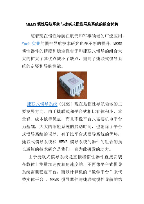
MEMS惯性导航系统与捷联式惯性导航系统的组合优势
随着现在惯性导航在航天和军事领域的广泛应用,Yach实业的惯性导航技术研究也在不断的提升,MEMS 惯性器件的精度和稳定性对于和捷联式惯导的组合大大的扩大了其优点减小了缺点,提高了捷联式惯导系统的定姿和导航性能。
捷联式惯导系统(SINS)现在是惯性导航领域的主要发展方向。
由于捷联式和平台式相比有体积小、重量轻、成本低等优点,而且不像平台式需要机电平台为基础,大大的缩短系统的启动时间,也消除了平台式惯导系统的误差。
有了比平台式惯导系统的优势,捷联式惯导系统和MEMS惯导系统的器件的组合的扬长避短的技术研究是我们一直为此研发的动力。
由于捷联式惯导系统是直接将惯性器件直接安装在载体上测量加速度和角速度的,不再像平台式惯导系统需要稳定平台,而以计算机的“数学平台”来代替实体平台。
MEMS惯导器件与捷联式惯性导航的结
合会大大的减小捷联式惯性导航在载体上的占用面积,系统硬件设计简化,成本降低。
这两种惯导的结合在未来会是军事和航天研究所追崇的惯导技术,既缩短系统的启动时间、降低误差;又拥有体积小、重量轻、成本低、功耗低的特点。
MEMS 惯导系统和捷联式惯导系统的结合无疑不是将来惯导系统的主要发展方向。
惯性导航系统技术的研究与发展

惯性导航系统技术的研究与发展惯性导航系统(Inertial Navigation System, INS)是一种利用惯性导航传感器测量和集成飞行器运动信息的导航技术。
它以惯性测量单元(Inertial Measurement Unit, IMU)为核心,通过测量加速度和角速度等物理量,计算出飞行器的位置、速度和姿态等导航参数。
惯性导航系统技术的研究与发展具有重要意义,不仅可以应用于航空航天领域,还可以拓展到其他领域,例如汽车、船舶等。
惯性导航系统技术的研究与发展主要包括三个方面:传感器技术、运动解算算法和误差补偿方法。
首先,传感器技术是惯性导航系统的基础。
目前常用的惯性导航传感器包括陀螺仪和加速度计。
陀螺仪用于测量飞行器的角速度,而加速度计则用来测量飞行器的加速度。
传感器的性能对系统导航精度和可靠性具有重要影响。
因此,研究人员致力于开发高精度、低成本、小尺寸的惯性导航传感器。
传感器技术的创新可以提供更准确的输入数据,从而提高惯性导航系统的性能。
其次,运动解算算法是惯性导航系统的核心。
传感器测量得到的加速度和角速度需要通过运动解算算法计算出飞行器的姿态、速度和位置等导航信息。
常用的运动解算算法包括卡尔曼滤波器、扩展卡尔曼滤波器等。
这些算法基于动力学模型和测量方程,结合先验信息和测量数据,通过迭代计算得到最优的导航解算结果。
研究人员对于运动解算算法进行改进和优化,旨在提高系统的导航精度和鲁棒性。
最后,误差补偿方法是惯性导航系统中不可或缺的一环。
由于传感器本身存在误差和漂移,以及环境条件的变化,惯性导航系统的导航参数会随着时间累积误差而发生偏移。
为了解决这个问题,研究人员提出了各种误差补偿方法。
常见的方法包括零偏校准、温漂补偿、初始对准等。
这些方法能够减小传感器误差对系统导航性能的影响,延长系统的导航有效性。
总的来说,惯性导航系统技术的研究与发展对于提高导航精度、降低成本、提升可靠性具有重要意义。
随着人们对于导航需求的不断提高和技术的不断进步,惯性导航系统将会得到更广泛的应用。
惯性导航技术发展与应用论文
惯性导航技术发展与应用【摘要】阐述了惯性导航的基本原理,并通过简图来表示出原理的示意图。
举出了常见的导航系统.总结了世界范围内惯性导航的发展历程与发展趋势,其中重点介绍了国内导航的发展路程。
而后简洁叙述了惯性导航的应用。
【关键词】惯性导航;平台式惯性导航;捷联式惯性导航0.引言惯性导航系统利用惯性敏感元件在飞机、导弹、舰船、火箭载体内部测量载体相对惯性空间的线运动和角运动参数,在给定的运动初始条件下,根据牛顿运动定律,推算载体的瞬时速度和瞬时位置。
惯性导航涉及到控制技术、计算机技术、测试技术、精密机械工艺等多门应用技术学科,是现代高精尖技术的产物。
1.惯性导航的基本原理在这里我们假设船舶在海面的较小范围内航行,这样舰船的活动区域可近似看作是一平面,球面导航就可以化为平面导航。
我们再假设载体的初始坐标(□,λ)。
载体是匀速航行,且东向、北向的分速度分别是ve0、vn0。
我们沿着船舶平台的正东方和正北方各安装一个加速度计,从这两个速度计中的输出,可以根据载体沿正东方向和正北方向的加速度:ae和an,并与初始速度相加得到载体的东向与北向速度。
ve=ve+atvn=ve+at也可以用再北向与东向的加速度的一次积分再与初速度求和,得到东向与北向的瞬时速度。
根据ve、vn可得出载体位置坐标经纬度(□,λ)的变化率,再积分则得到经纬度的变化量,加上初始坐标即可的载体的瞬时位置:□=□+∫vn/rdtλ=λ+∫ve/r cos□dt在惯性导航系统发展的过程中,一直存在着两种发展方向,即平台式与捷联式。
平台式方案是将陀螺仪安装在由框架构成的稳定平台上,用陀螺仪敏感平台的角运动,通过平台稳定回路使平台保持指向向上的稳定,把加速度计也放在稳定平台上,其敏感轴的指向也是明确的,加速度的输出信息由导航计算机处理,可方便地提取载体的加速度,计算载体速度、位置以及平台的控制量。
捷联式惯性导航系统,导航加速度计和陀螺直接安装在载体上。
机载惯性导航技术综述
①优点:完全自主、无源性、实时|生强、输出参数全
面
作者简介:雷宏杰,研究员,主要从事惯性导航,组合导航技术研究,先后多次获得国防与集团科技进步奖。
・_7・
万方数据
机载惯性导航技术综述 惯导的精度主要取决于惯性传感器——陀螺和加
速度计的精度,因此提高惯导系统精度的主要技术途径 一是提高惯性器件的精度或研制新型的惯性器件,如 航空惯导所采用的陀螺已经历了机电陀螺(液浮陀螺、 挠性陀螺)、光学陀螺(激光陀螺、光纤陀螺)、振动陀螺 (MEMS陀螺),目前的主要发展目标是基于物质波理论 和量子物理学理论的原子陀螺,理论精度可达5m/h。 二是采用组合导航手段,利用导航误差不随时间 积累的外部信息源对惯导进行校正,目前比较典型的 组合方式主要包括惯性/无线电组合、惯性/卫星组合、 惯性/天文组合、惯性/地形辅助导航等。 1.3使用需求 ①基本导航需求 机载惯导系统的基本功能是导航,即提供飞机的 在航空领域,随着航空电子综合化水平的提高,惯 导与用于侦察、控制、火力打击等设备之间的信息耦合 程度进一步加深,惯性信息已成为现代侦察一控制一
~_
1
[关键词】惯性技术;惯性导航;组合导航 [中图分类号】V249.32+3
0007-06
【文献标识码】A[文章编号】1003—5451(2016)01_
惯性原理基础上的惯性导航系统,除了地球引力场和
简介
自转角速度这两类先验导航环境外,不再需要其他任
何外来信息,也不会向外辐射任何信息,依靠自身就
1.1惯性导航系统概述 基于惯性元件(陀螺和加速度计)测量飞行器相对 惯性空间的线运动和角运动参数进行载体运动信息计 算的惯性导航技术,是各种复杂电磁对抗环境下自主 能在全天候条件下,在全球范围和任何介质环境里自 主、隐蔽地进行定位与导航,连续地提供角速度、加速 度、姿态、速度和位置等多种导航信息。这种同时具 备自主性、隐蔽性和能获取飞机完备运动信息的独特 优点是诸如无线电导航、卫星导航和天文导航等其他 导航系统无法比拟的,这些独特的优点使其成为机上 的中心信息源,具有其他任何导航系统无法代替的地 位。 ②缺点:误差随时间发散、成本高、初始对准时问 长 惯导本质上是一种航位推算系统,误差随时间积 累,长时间工作误差会超出允许范围,甚至失去导航能 力;惯性传感器的精度指标是决定产品价格的根本因 素,一般来讲机载惯导的价格比较昂贵;另外一点是初 始对准时间较长,也会对载机快速反应和机动作战能 力有一定影响。 由于惯性是所有质量体的基本属性,所以建立在 ③提高性能的途径
3捷联惯性导航系统原理 - search readpudncom
角 速 度 用带 有 上 下 标的 符 号 表 示, 如: 。 九 , 其下 标含义为b 系( 机 体 坐标系) 相
对于i 系( 惯性坐标系)的 转动角速度,上标含义为此角速度在b 系( 机体坐标系)中
的投影。 其它角速度符号含义与此相似。
( 5 ) 坐 标系 变换矩阵
( 5 ) 机 体 坐 标 系( 下 标为b ) - o x b y b z b
机体坐标下是固连在机体上的坐标系。
机体 坐 标 系的 坐 标原点。 位于 飞 行 器的 重 心 处,x b 沿 机体横 轴 指向 右,Y h 沿 机体
纵 轴 指问 前 , z 。 垂 直 于 o x h Y 6 , 并 沿 飞 行 器的 竖 轴 指 向 上。 x b y b z 。 构 成 右 手 坐 标系 机
坐 标 系 变 换 矩 阵 也 用 带 有 上 下 标的 符 号 表 示 , 如:心, 其 含 义 为n 系( 导 航 坐 标
系) 到b 系〔 机体坐标系)的 变换矩阵。其它坐标系变换矩阵符号的含义与此相似。
(பைடு நூலகம் 6 ) 地球半径:
的需要而选取的作为导航基准的坐标系。当把导航坐标系选得与地理坐标系重合时,可 将这种导航坐标系成为指北方位系统;为了适应在极区附近导航的需要往往将导航坐标
系 的z轴 仍 选 的 与z 轴 重 合, 而 使x 。 与x , 及Y , 与Y , 之 间 相 差 一 个自 由 方 位角 或 游 动 方
位角a,这种导航坐标系可称为自由方位系统或游动自由方位系统。
于其它类型的导航方案 ( 如无线电导 航、天文导航等)的根本不同 之处就在于其导航原 理是建立在牛顿力学定律一一又可称为惯性定修 一 的基础上的, “ 惯性导航” 也因此
惯性导航的应用和发展论文
南京理工大学导航定位技术概论课论文作者: ___________________ 学号: __________________学院(系” ________________________________________专业: ___________________________________________题目:惯性导神农百草育航的发展与应用指导者:______________________________________2012年9 月论文摘要目次1引言 ................................................................... 2惯性导航系统原理 .......................................................2.1惯性导航定位系统中的基本关系.......................................2. 2平台式惯性导航定位系统 ............................................2. 3捷联式惯性导航定位系统 ............................................ 3惯性导航技术的发展 .....................................................3.1惯性导航的发展历程.................................................3.2 惯性导航和其他筋络速通导航方式的组合4惯性导航技术的应用 .....................................................结束语................................................................参考文献..............................................................1引言惯性导航是一门综合了机电、光学、数学、力学、控制及计算机等学科的尖端技术,是现代科学技术发展到一定阶段的产物。
捷联惯性技术的发展及与平台惯导系统的对比
捷联惯性技术的发展及与平台惯导系统的对比捷联惯性技术是指利用惯性敏感器(通常使用加速度计和陀螺仪)来测量载体相对于惯性参考系的角速度和加速度,从而计算得到载体的姿态、速度和位置等参数的技术。
捷联惯性技术具有体积小、重量轻、可靠性高、成本低等优点,因此在军事、航空、航海等领域得到了广泛应用。
捷联惯性技术的发展可以追溯到20世纪60年代,当时美国国防部高级研究计划局(DARPA)开始资助一些研究项目,以探索将惯性敏感器直接固定在载体上的可能性。
随着微电子技术和制造工艺的不断发展,捷联惯性技术的性能得到了大幅提升,同时成本也得到了降低。
在捷联惯性技术的发展过程中,出现了多种不同的技术路线。
其中,卡尔曼滤波器是一种被广泛应用于捷联惯性系统的数据处理方法。
卡尔曼滤波器是一种最优估计方法,它能够利用观测数据和预测模型来估计系统的状态,同时考虑到观测噪声和模型误差。
在捷联惯性系统中,卡尔曼滤波器可以用于融合加速度计和陀螺仪的测量数据,以提高系统的性能和精度。
平台惯导系统是一种基于平台稳定性的惯性导航系统。
它通过将惯性敏感器安装在稳定的平台上,可以大大提高系统的精度和可靠性。
平台惯导系统通常由平台、惯性敏感器、控制系统和数据处理系统等组成。
其中,平台是整个系统的支撑结构,惯性敏感器用于测量载体的角速度和加速度,控制系统用于控制平台的运动轨迹,数据处理系统则用于对测量数据进行处理,得到载体的姿态、速度和位置等参数。
与捷联惯性技术相比,平台惯导系统具有更高的精度和可靠性。
这是因为在平台惯导系统中,惯性敏感器可以安装在稳定的平台上,从而消除了载体运动对测量数据的影响。
此外,平台惯导系统还可以通过控制系统来实现主动减震,以进一步提高系统的性能和精度。
然而,平台惯导系统也存在一些缺点。
首先,它的体积和重量较大,不利于小型化和轻量化。
其次,它的成本较高,不利于大规模应用。
最后,它的维护和校准难度较大,需要专业人员和技术支持。
- 1、下载文档前请自行甄别文档内容的完整性,平台不提供额外的编辑、内容补充、找答案等附加服务。
- 2、"仅部分预览"的文档,不可在线预览部分如存在完整性等问题,可反馈申请退款(可完整预览的文档不适用该条件!)。
- 3、如文档侵犯您的权益,请联系客服反馈,我们会尽快为您处理(人工客服工作时间:9:00-18:30)。
III WORKING MODE OF GAINSThe process of the GAINS is displayed in Figure 2. The navigation processor is composed of correlation processor and kalman filter. There are two main inputs, one is the signal processed and compensated from magnetometers, the other is the output collected and calibrated from IMU. After filter estimates, the navigation processor will provide the optimal information about the vehicle. Because motive vehicle in the geomagnetic field induces its own magnetic field, the signalsof the three-axis magnetometers are available only after the degauss regulator processes. Appropriate registration area is chosen by the correlation processor from the stored geomagnetic map using geomagnetic entropy criterion, and then compares real-time sequence based on calibrated magnetic values with chosen registration map to find the closest match resultsof magnetic contours and develops latitude and longitude reference information. Kalman filter, the core of the processor, processes inertial and reference datato continuously update the output of inertial navigation system.Fig.2 Flow diagram of GAINS processA.Geomagnetic Matching Areaa) Geomagnetic Field and modelAs intrinsic resource, the geomagnetic field influences all the orbits with electricity and magnetism on the earth, meanwhile it provides natural coordinate for aviation, aerospace and sailing. The earth’s magnetic field is complicated, viewed as a sum of several contributions including the main field, the anomaly field and external source fields[5]. The geomagnetic model is established to describe the filed. Although International Geomagnetic Reference Field(IGRF[6]) and World Magnetic Model(WMM[7])are popular models to approach the main geomagnetic field in a large-scale range, they are not accurate enough to precise navigation because magnetic fields originating from sources within the earth’s crust, ionosphere and magnetosphere have been removed.b) Selection of Matching AreaThe geomagnetic map stored in the vehicle is in closed relation with the model, but the navigation effect is related with the uniqueness of matching area. Geomagnetic entropy is presented to evaluate the character of magnetic matching region, because it represents information about magnetic field in the registration region. Geomagnetic entropy H is defined in (1).1logNi i iiH P P==−∑,2211,,k li l kk ll l k kMPM===∑∑(1)where,k lM is all the magnetic value in the matching area, k,l are the numbers of matching area grid and i is serial number of matching district.Geomagnetic entropy reflects the size of geomagnetic information in the matching region. The smaller entropy is, the more information is and the better the matching result is. So it’s good criterion to judge the performance of magnetic matching area and measure the uniqueness of magnetic matching area, which provides a basis for the selection of matching area.B. Matching Algorithms in GAINSa) Contour Matching AlgorithmThe contour mapping is the main matching algorithm due to simple theory and batch processing, which is used in a wide range in the terrain and gravity aided systems. The common rule is MSD(mean square deviation) as shown in (2).211(,)()NMSD n j nnR L x yNλ+==−∑(2)Where n jx+is magnetic value in matching region, andny is value measured from magnetometer. N is matching lengthand j is displacement parameter. When (,)MSDR Lλ is minimum, (,)Lλ is determined as reference position.From the definition of contour matching, the defects of algorithm are obvious.1) Precision of matching results is restricted by the accuracy of the map grid.2) When the initial position error is relatively large, the search area must be enlarged to find the matching location. Calculation will increase correspondingly which impact the real-time algorithm seriously.3) The number of optimum match location may not be the only one due to the relevance of the geomagnetic filed in the matching region.b) ICCP AlgorithmIterated Closest Contour Point (ICCP) algorithm is derived from ICP which is widely used in image registration[8].ICP algorithm can be applied to free-form objects without requiring discrete correspondences between the two images. Geomagnetic digital map is represented in contour line. Theposition in the measured magnetic value isoclines is chosen as match model and track computed from INS is used to find the original track. Eulerian distance is regarded as object function in (3). The optimum transformation is calculated when object function reach a minimum value. It is used to rectify INS track. Compared with contour matching algorithm, ICCP method decreases the computational burden and avoids the wrong matching result. Matching location can be more precise because the search area is limited nearby isoclines instead of in the matching area used in contour matching.21(,)(,)NICCP n R K TI d K TI ==∑(3)Where (,)d i i is Eulerian distance between the two track, and K is track in the measured magnetic value isoclines and I is track computed form INS. When (,)ICCP R K TI is minimum, T is determined as optimum transformation. The ICCP flow diagram [9] is displayed in Figure3.Fig 3. ICCP flow diagramc) Information FusionKalman filter is widely used in the integrated navigation system. According to positioning requirements, the system variables are defined as follows:131[]TE N U E N x y z x y z X v v L φφφδδδδλεεε×=∇∇∇ E φ,N φ,U φ- attitude misalignment angles in the directionof east, north and upE v δ,N v δ- velocity error in the east and northL δ,δλ- error of latitude and Longitude x ε,y ε,z ε- drifts of the three gyroscopes x ∇,y ∇,z ∇- drifts of the three accelerometersSystem state equation is followed as:()()()()()X t F t X t G t W t =+i(4)W(t) is white noise in the gyros and accelerometers with expected values ()~(0,)W t Q . Measure equation is shown as12()[]()()T Z t z z HX t V t ==+(5)1z ,2z are the differences of latitude and longitude betweenthe strapdown INS and matching method. H is a zero matrix with dimension 213×, except that (1,6)1H =and (2,7)1H =. V(t) is observation noise matrix, which is whitenoise with expected values ()~(0,)V t R .IV.SIMULATIONBeijing geomagnetic anomaly field is used in the simulation. Geomagnetic map is shown in Fig4.Fig4. Beijing geomagnetic anomaly fieldMatching area B is chosen rather than area A from Fig4 using geomagnetic entropy criterion. The parameters about two regions are listed in Table1.A BTABLE 1COMPARISON BETWEEN TWO MATCHING REGIONSA BLongitude range (deg) 116.46~116.79 116.60~116.93 Latitude range (deg) 40.28~40.62 39.70~40.03 Grid accuracy (deg) 0.002 0.002 Permissible locationerror(m) 200 200Flying length(m) 25000 25000 Geomagnetic entropy 0.0176 0.0166Parameters in vehicle and inertial component are listed in Table 2. Three tracks shown in Fig.5 are true track, INS track and GAINS track based on ICCP algorithm. MSD and ICCP methods are used as matching algorithm respectively to compare matching effect. Longitude and latitude errors using two algorithms are shown in Fig.6 and Fig.7.TABLE 2PARAMETERS IN VEHILE AND INERTIAL COMPONENTSparameter valueInitial north location error (deg) 0.003Initial east location error (deg) 0.003Initial north velocity error (m/s) 0.1 Initial east velocity error (m/s) 0.1 Gyro zero-bias (/h )0.2 Accelerator zero-bias (2/m s )0.001 variance in measured value (nT)2 Flying time(s)125Fig 5. Simualtion trial for GAINSFig 6. Longitude and Latitude Errors using MSD algorithmFig7. Longitude and Latitude Errors using ICCP algorithmFig.5-7 show that longitude and latitude errors fromGAINS system don’t diverge over time unlike pure INS. It’s obvious that better performance and higher accuracy can be obtained by using ICCP algorithm than MSD algorithm from Fig.6 and Fig.7. Simulations illustrate the feasibility and theadaptability of the architecture of simulation platform. V. CONCLUSIONThe paper describes basic theories, composition of GAINS, and then key technologies, such as selection with geomagnetic entropy, matching method using MSD and ICCP are analyzed. The GAINS system is established to validate better performance using ICCP algorithm.A CKNOWLEDGMENTThe author is grateful to the help of Huang xue-gong. Special thanks to National Earth System Science Data Sharing Network for the support of geomagnetic data.REFERENCES[1]Feizhou Zhang, Xiuwan Chen Min Sun et al. "Simulation Design of Underwater Terrain Matching Navigation Based on Information Fusion". Geoscience and Remote Sensing Symposium. IEEE 2004, Vol. 5, pp. 3114-3117.[2] Feizhou Zhang, Xiuwan Chen Min Sun et al. "Simulation Study ofUnderwater Passive Navigation System Based on Gravity Gradient". Geoscience and Remote Sensing Symposium. IEEE 2004, Vol. 5, pp. 3111-3113.[3] Goldenberg F. "Geomagnetic Navigation beyond MagneticCompass". San Diego, California. pp.684-694, 2006.[4] S.K. Kiselev, "Airborne Magnetometric Navigation Systems and theProspects for Their Practical Use," Automation and Remote Control, Vol.62, pp. 1138-1145 , 2001.[5] S. Macmillan, S. McLean, S. Maus, et al. "The US/UK WorldMagnetic Model for 2005-2010", NOAA Technical Report NESDIS/NGDC-1, 2004.[6] IAGA Division 5, Working Group 8, "The 9-th GenerationInternational Geomagnetic Reference Field," Geophys. J. Vol. 155, pp. 1051-1056, 2003.[7] S. Macmillan, J. M. Quinn, "The 2000 revision of the joint UK/USgeomagnetic field models and an IGRF 2000 candidate model," Earth Planets Space. pp.1149-1162, 2000.[8] Byung-Uk Lee, Chul-Min Kim, Rae-Hong Park. "An orientationreliability matrix for iterative closest point algorithm". IEEE Transactions on Pattern Analysis and Machine Intelligence, Vol. 22 pp.1205-1208, 2000.[9] SUN Yang. Research on the Geomagnetic Map Matching Method ofTrue track*+IN S track G A IN S trackAUV. Master thesis, National University of Defense Technology, China, 2006.。