熔断器规格书
RS309-MF选型规格书

Kv
1.20
1.15
1.10
1.05
1.00
123456 强制冷却风速 (m/s)
安全使用和维护保养 a) 熔断器安装时,相邻两个熔断器带电零件的最小间隙满足绝缘要求,必要的话在熔断器之间装绝缘
隔板,以防止带电更换熔断器时引起相间短路。 b) 结合电气设备定期检修,进行检查和维护保养,清除尘埃、接触导电部位的氧化层等。 c) 对有机械损伤的熔断器必须进行更换。 d) 除非使用要求允许,如熔断器式负荷开关,否则请勿带负载更换熔断器。
欢迎垂询,或访问我公司网站
225A-800A-时间-电流特性曲线
225A-800A Time-Current Curve
104 103 1 02
10
500A
600A
1
225A
700A
250A
800A
0.1
300A
350A
10-2
400A
450A
10-3
10-4
102
安装方式
安装螺栓 M6
电气熔断器说明书
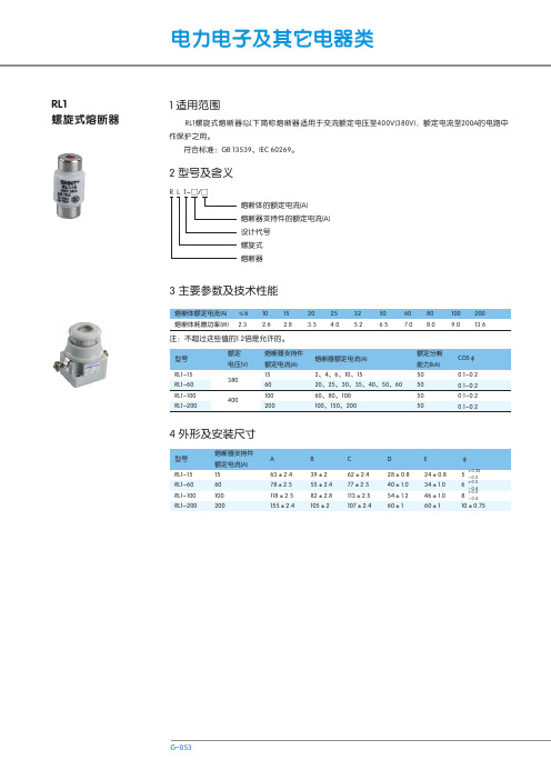
V14-T1-1Fuses GeneralCurrent Limiting FusesExpulsion Fuses1.1Product OverviewPower Fuse . . . . . . . . . . . . . . . . . . . . . . . . . . . . . . . . . . . . . . . . . . . . .V14-T1-2Power vs. Distribution . . . . . . . . . . . . . . . . . . . . . . . . . . . . . . . . . . . . .V14-T1-2Low vs. Medium vs. High Voltage . . . . . . . . . . . . . . . . . . . . . . . . . . . .V14-T1-2Expulsion vs. Current Limiting (Definitions per ANSI C47.40-1993). . .V14-T1-3Current Limiting Fuse Types. . . . . . . . . . . . . . . . . . . . . . . . . . . . . . . . .V14-T1-3General Fuse Component Terms . . . . . . . . . . . . . . . . . . . . . . . . . . . . .V14-T1-31.1Fuses GeneralProduct OverviewTypical Eaton FusesContentsDescription PageCurrent Limiting Fuse Types . . . . . . . . . . . . . . . . .V14-T1-3Expulsion vs. Current Limiting(Definitions per ANSI C47.40-1993). . . . . . . . . . .V14-T1-3General Fuse Component Terms. . . . . . . . . . . . . .V14-T1-3Product OverviewPower FuseEaton’s roots in themedium voltage powerfuse business beganover 75 years ago underWestinghouse® Electric.In 1935, Westinghouseintroduced the mediumvoltage boric acid expulsionfuse followed by the mediumvoltage current limiting fuse.Even today, medium voltagefuses continue to use thatcore technology. Eatoncontinues to build onthe technology legacyby engineering highperformance, cost-effectivepower fuse products.Eaton’s medium voltagefuses are manufactured andtested to the requirementsof the C37-4X series ofstandards that are maintainedand updated regularly tomaintain currency withindustry practices. Thesestandards are:IEEE Std. C37.40™IEEE Standard ServiceConditions and Definitionsfor High Voltage Fuses,Distribution Enclosed Single-Pole Air Switches, FuseDisconnecting Switches,and Accessories (ANSI).IEEE Std. C37.41™IEEE Standard DesignTests for High-Voltage(>1000V) Fuses, Fuse andDisconnecting Cutouts,Distribution Enclosed Single-Pole Air Switches, FuseDisconnecting Switches, andFuse Links and Accessoriesused with These Devices(ANSI).IEEE Std. C37.42™IEEE Standard Specificationsfor High-Voltage (>1000V)Expulsion-Type Distribution-Class Fuses, Fuse andDisconnecting Cutouts,Fuse DisconnectingSwitches, and Fuse Links,and Accessories used withThese Devices (ANSI).IEEE Std. C37.46™IEEE Standard Specificationsfor High Voltage Expulsionand Current Limiting TypePower Class Fuses and FuseDisconnecting Switches.IEEE Std. C37.47™IEEE Standard Specificationsfor High Voltage CurrentLimiting Type DistributionClass Fuses and FuseDisconnecting Switches.The following IEEE standardsare also applicable to the fuseproducts covered in thispublication:IEEE Std. C37.48™IEEE Guide for theApplication, Operation, andMaintenance of High VoltageFuses, Distribution EnclosedSingle-Pole Air Switches,Fuse DisconnectingSwitches, and Accessories(ANSI).IEEE Std. C37.48.1™IEEE Guide for theClassification, Application,and Coordination of Current-Limiting Fuses with RatedVoltages 1–38 kV.A better understanding ofsome fuse terminology willhelp you understand andselect the correct fuse. Thefollowing is a brief overviewof those terms.Power vs. DistributionThe differentiation is intendedto indicate the test conditionsand where fuses are normallyapplied on an electricalsystem, based on specificrequirements for generatingsources, substations anddistribution lines. Eachclass has its own uniqueset of voltage, current andconstruction requirements(see C37.42, .46 and .47).Low vs. Medium vs.High VoltageWhile fuses are defined inthe ANSI standards as eitherlow or high voltage, Eatonhas elected to name theirfuses to correspond with theequipment in which they areinstalled. Therefore, per ANSIC84, our fuses are namedas follows:●Low voltage—1000V andbelow●Medium voltage—greaterthan 1000 to 69,000V●High voltage—greater than69,000VV14-T1-2V14-T1-31.1Fuses GeneralProduct OverviewExpulsion vs. CurrentLimiting (Definitions per ANSI C47.40-1993)An expulsion fuse is a vented fuse in which the expulsion effect of the gases produced by internal arcing, either alone or aided by other mechanisms, results in current interruption.A current limiting fuse is a fuse that, when its current responsive element is melted by a current within the fuse’s specified current limiting range, abruptly introduces a high resistance to reduce current magnitude and duration, resulting in subsequent currentinterruption. Refer to Fuse Types Protection Range figure below for a features comparison.An expulsion fuse is not current limiting and as aresult limits the duration of a fault on the electrical system, not the magnitude.Current Limiting Fuse TypesThere are three current limiting fuse types: Backup, General Purpose and Full Range. It is important that the user have an understanding of these definitions to ensure proper application of the fuse (see Fuse Types Protection Range figure below).Backup FusesA fuse capable of interrupting all currents from themaximum rated interrupting current down to the rated minimum interrupting current.Backup fuses are always used in a series with another interrupting device capable of interrupting currents below the fuse’s minimum interrupting current.General Purpose FusesA fuse capable of interrupting all currents from the rated interrupting current down to the current that causes melting of the fusible element in no less than one hour.General Purpose fuses are typically used to protect feeders and components such as transformers.Full Range FusesA fuse capable of interrupting all currents from the rated interrupting current down to the minimum continuous current that causes melting of the fusible element, with the fuse applied at the maximum ambient temperature specified by the manufacturer.General High Voltage Fuse ComparisonFuse Types Protection RangeExpulsion Current Limiting VentedSealed Electromechanical StaticInterrupts at current zeroLimits fault currentGenerally higher voltage and current application capabilitiesGenerally higher interrupting ratings Different time/current characteristicsDifferent time/current characteristicsC u r r e n t L i m i t i n g T y p eInterrupting Currenti i hr.i min.i max.i max. — Maximum rated interrupting current i min. — Minimum rated interrupting currenti hr. — Current causing element melting in 1 houri — Any current melting element with no time limitGeneral Fuse Component TermsFuse Refill Unit (of an Expulsion Fuse)A fuse refill unit is a replaceable assembly containing the calibrated current-responsive fuse element and certain other items that facilitate current interruption. On its own, the refill unit has no interrupting ability. A refill unit must be mounted in a fuse holder with a spring assembly to form a refillable fuse unit. The refill unit is the section of the fuse that must be replaced after a fuse operation.Fuse Holder (of an Expulsion Fuse)A fuse holder is a reusable holder that when equipped with a fuse refill unit forms a fuse unit, capable of interrupting an overload or fault current. A fuse holder is supplied with a spring and shunt assembly, necessary to complete the internal interrupting assembly. The spring and shunt assembly is supplied with the fuse holder but is also available as a replacement part, as it may need replacement after several of heavy operations.Fuse UnitA fuse unit is a replaceable unit or assembly that isable, on its own, to perform current interruption. Inthe case of a refillable fuse unit, the refill unit must be replaced after a fuseoperation. Where a complete fuse unit is supplied from the factory, the complete fuse unit must be replaced after a fuse operation. All current-limiting fuses are fuse units.Exhaust Control DeviceWhen expulsion fuses are used in enclosures, exhaust control devices (filters,condensers or mufflers) are used to control the sound of the fuse operation, and to de-ionize and absorb the fuse exhaust products. These devices are normally supplied separately, because ofdifferent characteristics and ratings. They are reusable but may need replacement after several heavy operations.MountingA mounting provides all the necessary parts to safely mount a fuse in its intended piece of equipment. The base is the metal support to which all other pieces attach. Insulators attach to the base and insulate the live fuse unit from the base and everything beyond the base. Live parts are the parts of the mounting that are energized onceelectricity is flowing. The live parts provide the means to hold the fuse unit in place, electrical contact, and a place to make line and load connections.Non-Disconnect Mounting A non-disconnect mounting does not provide a means for removing the fuse unit until the circuit is dead and the fuse unit can be removed manually. The fuse unit is held in place by friction through the use of fuse clips or by a cross bar.1.1Fuses GeneralProduct OverviewDisconnect MountingThe disconnect mountingallows the fuse unit to beremoved (off load) using aninsulated switch stick. Theswitch stick grabs a pull ringand disconnects the fuse unitthat may then be lifted out ofits mounting.Dropout MountingDropout mountings areused in outdoor applications.The fuse unit is equippedwith a mechanical trigger thatunlatches the upper contact,allowing the fuse unit to dropout, increasing the dielectricseparation, and providingvisible indication of ablown fuse.Live PartsLive parts were brieflydiscussed as part of the“Mounting” definition.Everything above theinsulators on the mountingexcluding the fuse unit, fuseholder, and the fuse endfittings (if required) areconsidered the live parts. Fuseend fittings are discussednext and are not requiredwith non-disconnect liveparts, but are required andincluded with disconnect liveparts. Live parts may be soldseparately as replacementparts or for new OEMapplications.End FittingsEnd fittings are metal partsthat attach to each end of afuse unit’s ferrules (end caps).As previously mentioned,they are used solely withdisconnect fuse applicationsor when converting a non-disconnect to a disconnectfuse configuration.When end fittings areordered, a fitting for each endof the fuse is included. Keepin mind that end fittings canbecome damaged in use and,therefore, are sold separatelyfrom the live parts whennecessary. It is not necessaryto purchase an entire set oflive parts when only the endfittings are required.V14-T1-4。
RL1 螺旋式熔断器 说明书
COSφ
0.1~0.2 0.1~0.2 0.1~0.2 0.1~0.2
G
4 外形及安装尺寸
型号
RL1-15 RL1-60 RL1-100 RL1-200
熔断器支持件 额定电流(A) 15 60 100 200
A
63±2.4 78±2.5 118±2.5 155±2.4
B
39±2 55±2.4 82±2.8 105±2
C
62±2.4 77±2.5 113±2.5 107±2.4
D
28±0.8 40±1.0 54±1.2 60±1
E
24±0.8 34±1.0 46±1.0 60±1
φ
+0.55
5
-0.2 +0.5
6
-0.4 +0.5
8
-0.4
10±0.75
G-053
电力电子及其它电器类
E
C
M
D
A
φ
B
5 订货须知
5.1 订货时必须指明: 5.1.1 熔断体应指产品型号、额定电流、数量。 5.1.2 底座应指明型号规格、注明底座、定货数量。 5.2 订货示例
熔断体的额定电流(A) 熔断器支持件的额定电流(A) 设计代号 螺旋式 熔断器
3 主要参数及技术性能
熔断体额定电流(A) ≤6 10 15
20 25 32
50
60 80
100 200
熔断体耗散功率(W) 2.3 2.6 2.8 3.3 4.0 5.2 6.5 7.0 8.0 9.0 13.6
注:不超过这些值的1.2倍是允许的。
4
20A
16A
3
10A
2
6A
4A
1
电阻熔断器数据表说明书

Description:Basic protection Class G size-rejecting, current limiting fuses. ½ to 6A Fast-acting, 7 to 60A time-delay. Time-delay – 12 seconds (minimum) at 200% of rated current. Catalog Symbol:SC-(amp)Ratings:Volts— 600Vac/170Vdc (½-20A)— 480Vac/300Vdc (25-60A)Amps— ½-60AIR— 100kA Vac RMS Sym.— 10kA VdcAgency Information:CE, UL Listed, Std. 248-5, Class G, Guide JDDZ, File E4273 CSA Certified, C22.2 No. 248.5, Class 1422-01, File 53787 Catalog Numbers (amps)SC-1⁄2SC-6SC-30SC-1SC-7SC-35SC-11⁄2SC-8SC-40SC-2SC-10SC-45SC-21⁄2SC-12SC-50SC-3SC-15SC-60SC-4SC-20SC-5SC-25Carton Quantity and WeightAmp Rating Carton Qty.½-15420425–30235–602Dimensions - in Amp RatingA½-15 1.31 (33.3)20 1.41 (35.8)25 to 30 1.62 (41.1)35 to 60 2.25 (57.1)Features:•Compact branch-circuit units with high interrupting ratingand current-limitation•With up to a 600V rating, they can be used in 120/208V,120/240V and 277/480V circuits•Size rejection by length helps prevent overfusing•In general, SC fuses are about 1⁄2the size of the 600V NEC®fuse type•SC fuses 7 amps and above have a degree of overloadtime-delay which permits them to pass temporary overloadsRecommended Fuse BlocksFuse Amps1-Pole2-Pole3-Pole1⁄2-15BG30011_BG30012_BG30013_20BG30021_BG30022_BG30023_25-30BG30031_BG30032_BG30033_35-60G30060-1C_G30060-2C_G30060-2C_For additional information on the BG and G Series of Class Gfuse blocks, see Data Sheet # 1006.CMA/Flodyne/Hydradyne▪MotionControl▪Hydraulic▪Pneumatic▪Electrical▪Mechanical▪(8)426-548▪wwTime-Current Curves - Average MeltC M A /F l o d y n e /H y d r a d y n e ▪ M o t i o n C o n t r o l ▪ H y d r a u l i c ▪ P n e u m a t i c ▪ E l e c t r i c a l ▪ M e c h a n i c a l ▪ (800) 426-5480 ▪ w wCurrent-Limitation CurvesThe only controlled copy of this Data Sheet is the electronic read-only version located on the Cooper Bussmann Network Drive. All other copies of this document are by definition uncontrolled. This bulletin is C M A /F l o d y n e /H y d r a d y n e ▪ M o t i o n C o n t r o l ▪ H y d r a u l i c ▪ P n e u m a t i c ▪ E l e c t r i c a l ▪ M e c h a n i c a l ▪ (800) 426-5480 ▪ w w。
rn2-10熔断器参数
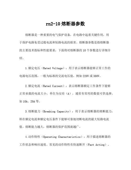
rn2-10熔断器参数熔断器是一种重要的电气保护设备,在电路中起着关键作用,用于保护电路免受过载电流和短路电流的损害。
熔断器参数是指熔断器的主要技术指标和性能要求,下面将对熔断器的10个参数进行详细介绍。
1.额定电压(Rated Voltage):用于表示熔断器能够正常工作的电源电压范围,一般为标准的交流电压值,例如220V或380V。
2.额定电流(Rated Current):表示熔断器额定工作条件下能够正常承载的电流大小,单位为安培(A),通常有常用的数值可供选择,如10A、20A等。
3.熔断能力(Breaking Capacity):用于表示熔断器的熔断能力,即在额定电流和额定电压条件下能够可靠地切断电流的最大短路电流值。
熔断能力越大,熔断器的保护范围就越广。
4.动作特性(Operating Characteristics):用于描述熔断器的工作状态和响应速度。
常见的动作特性有快速断开(Fast Acting)、延时断开(Time Delay)等。
根据应用场合和需要选择不同的动作特性。
5.额定断电能力(Interrupting Capacity):表示熔断器在短路情况下能够安全切断电路的能力,是熔断器性能的重要指标之一。
额定断电能力越大,熔断器的安全性能越高。
6.漏电保护性能(Leakage Protection Performance):用于指示熔断器对于漏电保护的性能。
漏电保护熔断器能够在电路出现漏电故障时迅速切断电流,保护人身和设备的安全。
7.额定冲击电流(Rated Impulse Withstand Voltage):用于指定熔断器可以承受的额定冲击电压大小。
冲击电流是指由于电路突然中断而产生的电压冲击,额定冲击电流越高,熔断器的抗干扰能力越强。
8.额定热电流(Rated Thermal Current):表示熔断器能够长时间连续工作的最大额定电流。
熔断器在额定热电流条件下能够长时间工作而不发生过热现象,保证电路的正常运行。
高压熔断器技术参数

概述:户外高压熔断器适用10kV,额率48Hz-62Hz交流电力系统中作输电线路和电力变压器的短路保护与过电流保护。
产品性能特点本产品是一种顶盖密封、抗风雪、抗污秽能力强,内插式结构双点灭弧的输电保护装置。
熔断器绝缘体采用新型材料骨架涂耦连剂后一次模压硫化成型。
具有强度高、重量轻、抗拉抗弯能力强等优点,完全克服了传统的瓷质绝缘体怕碰易碎,不适温度急剧变化而自爆裂的缺点。
适用范围1.产品基本使用条件:1)海拔高度:普通型不超过3000米2)环境温度不高于40℃,不低于-40℃2.产品不适用于下述场所:1)有燃烧或爆炸危险场所。
2)有剧烈震动或冲击场所。
3)有导电化学气体作用及严重脏污、盐雾地区。
动作原理及结构特征熔断器由绝缘体、上下防污罩、上下触点、灭弧管等组成,灭弧管采用内插式,可360°旋转安装(克服同类产品的安装,使用不便的缺点)双点灭弧。
当熔丝熔断时,利用悬落点可迅速灭弧,瞬间开断,形成明显断开指示。
高压熔断器技术参数表o HRW3-10-100~20面议/o HRW3-10-100~20面议/o RW7-10/100~200面议/o RW9-10/100~200面议/o RW12-12/100~20面议/o RW12-10/100~20面议/o HRW10-10/100~2面议/PRW5-12~40.5型熔断器详细说明:PRW5-12~40.5型熔断器是从韩国平日株式会社成套引进技术,采用大爬距防污型高强度电瓷,不锈刚支件,铜合金的动静触头,玻璃纤维复合材料制作的熔管及不锈钢件,使熔断器具有可靠的机械和电气性能。
该产品主要用于12KV线路,开关断路电流或过负荷电流,适用于分线路及工矿企业配电系统中的保护。
技术参数:。
熔断器选型手册
型号额定电压额定电流产品描述页NH 380V~690V AC 2A~1600A 插刀型NH普通熔断器gG-gL 2 KH 500V~1250V AC 10A~2200A 插刀型半导体保护熔断器gR aR 3 KSZ 500V~4000V AC 10A~1500A 钩叉型半导体保护熔断器gR aR 5 KSP 380V~6000V AC 30A~4000A 平板型(单孔)半导体保护熔断器gRaR7 KSP双孔380V~1300V AC 1100A~4500A 平板型(双孔)半导体保护熔断器gRaR9 RSH 400V~2000V AC 630A~3600A方型台面半导体保护熔断器aR10 KSM 500V~1250V AC 40A~2000A 长圆孔直母线型半导体保护熔断器gR aR11 RSF 500V~1500V AC 450A~2000A L型半导体保护熔断器aR12 RS0/RS3 250V~750V AC 10A~1000A L型半导体保护熔断器aR13KRF 150V~700V AC150V~700V DC 35A~1000A 北美圆柱型半导体保护熔断器gRaR14KSH 500V~2000V AC 700A~7000A 双并结构半导体保护熔断器aR15 KSC 250V~1000V AC 800A~5000A 双并结构半导体保护熔断器aR17KG/KS/KD 380V~700V AC440V~1000V DC 1A~170A 圆管型普通熔断器半导体保护熔断器直流熔断器gG-gL aM gR aR19熔断器配套底座20熔断器隔离开关LTL系列22特性曲线23西安开尔泰电力电子制造有限公司坐落于古城西安,主要从事熔断器的研制、开发与销售。
公司主要产品有:快速熔断器、直流熔断器、NH熔断器。
熔断器产品性能稳定,具有分断能力高、限流特性好、时间-电流误差小、功率损耗低等优点。
在电气特性上等效于进口熔断器,可替代Bussmann巴斯曼170M系列快速熔断器,Ferraz罗兰快速熔断器、直流熔断器,Siemens西门子3NE系列快速熔断器、3NA普通熔断器,Siba西霸熔断器,Jeanmuller熔断器等。
RS309-MF选型规格书
c) 一般情况下,在开放环境使用的熔断器,可忽略海拔高度对额定电流的影响,仍然按照标准条件选用。
d) 在封闭环境使用的熔断器,如果其箱体的环境空气温度或箱体内部的温度并不随海拔升高而明显下降,
仍然可以达到40℃以上,则需要对额定电流降容。海拔每升高1000米,额定电流降容2%-5%。
注:同一尺寸系列中,最大额定电流采用较高的降容比例,较小的额定电流采用较低的降容比例。
允许工作条件
无明显凝露情况下,相对湿度可达95%。
震动环境及耐受地震等灾害能力
本系列熔断器有良好的抗振动和冲击的耐受能力,可承受10g以上的加速度。
本系列熔断器抗振动和冲击的耐受能力,符合轨道交通II类应用环境。
本系列熔断器抗振动和冲击的耐受能力,适合一般机动车辆使用。
振动较为强烈的应用环境,欢迎咨询。一般要经过测试和验证 。
小体积 低功耗 高分断能力
欢迎垂询,或访问我公司网站
RS309-MF圆管螺栓连接式快速熔断器
AC/DC700V(IEC)&750(UL) 5-800A
产品基本资料 ● 螺栓连接式快速熔断器,尺寸和性能符合GB13539、IEC60269、UL248 ● 额定电压:AC/DC700V或低于(IEC) 、750(UL) ● 额定电流:5~800A ● 保护类别:aR(IEC) ● CE、UL认证,符合欧盟和中国RoHS指令 ● 分断能力:AC100KA、DC50kA(时间常数≤15ms)
的熔断体外,无需校核绝缘间隙。
c)熔断器带与其它带电结构间,以及对地的绝缘间隙,需要由用户考虑海拔高度的影响。
大气条件
正常工作条件
空气是干净的,它的相对湿度在最高温度为40℃时不超过50%。
在较低温度下可以有较高的相对湿度,例如,在20℃下,相对湿度可以达90%。
AGA系列快速作用玻璃管熔断器说明书
1/4" x 5/8" Fast-Acting,Glass Tube FusesAGA SeriesDescription•Fast-acting•1/4" x 5/8" (6.4 x 15.9mm) physical size•Glass tube,nickel-plated brass endcap construction •Optional axial leaded version available •UL Listed product meets standard 248-14Agency Information•UL Listed,Guide JDYX,File E19180 (AGA:0 - 3 1/2A)•UL Recognized,Guide JDYX2,File E19180 (AGA:12 - 30A)Ordering•Specify packaging,product and option codeDimensions - mm (in)*Interrupting Rating:Interrupting ratings has been measured at 70%-80% power factor.**DC Cold Resistance (Measured at <10% of rated current)***UR Component Recognized at 125Vac 100A IRSpecificationsPart Number Voltage RatingAC Interrupting Rating* (Amps)Typical DC ColdResistance (Ω)**(Amps)Vac 250Vac 125Vac 32Vac Lower Upper AGA-1/102503510,000- 6.1868.370AGA-1/42503510,000-0.6490.879AGA-1/22503510,000-0.2230.301AGA-3/42503510,000-0.1160.157AGA-12503510,000-0.0880.118AGA-1-1/225010010,000-0.0560.076AGA-2250100200-0.0380.052AGA-2-1/2250100200-0.0270.036AGA-3250100200-0.0220.030AGA-5125-1000-0.0130.017AGA-6125-100010000.0110.015AGA-7125-100010000.0080.011AGA-7-1/2125-100010000.0080.010AGA-10125-100010000.0060.008AGA-15***32--10000.0030.004AGA-20***32--10000.0020.003AGA-25***32--10000.0010.002AGA-30***32--10000.0010.002Time-Current Characteristic Curves–Average MeltCURRENT IN AMPSPackaging CodePackaging Code DescriptionBK100 fuses packed into a cardboard cartonBK88000 fuses packed into a cardboard cartonOption CodeOption Code DescriptionB Board Washable - Hermetically sealed to withstand aqueous cleaningThe only controlled copy of this Data Sheet is the electronic read-only version located on the Cooper Bussmann Network Drive.All other copies of this document are by definition uncontrolled.This bulletin is intended to clearly present comprehensive product data and provide technical information that will help the end user with design applications.Cooper Bussmann reserves the right,without notice,to change design or construction of any products and to discontinue or limit distribution of any products.Cooper Bussmann also reserves the right to change or update,without notice,any technical information con-tained in this bulletin.Once a product has been selected,it should be tested by the user in all possible applications.Life Support Policy:Cooper Bussmann does not authorize the use of any of its products for use in life support devices or systems without the express written approval of an officer of the Company.Life sup-port systems are devices which support or sustain life,and whose failure to perform,when properly used in accordance with instructions for use provided in the labeling,can be reasonably expected to result in significant injury to the user.。
GDA系列快速作用,高挠能力熔断器说明书
Dimensions
Drawing Not to Scale
Product Code
GDA-50mA GDA-63mA GDA-80mA GDA-100mA GDA-125mA GDA-160mA GDA-200mA GDA-250mA GDA-315mA GDA-400mA GDA-500mA GDA-630mA GDA-800mA GDA-1A GDA-1.25A GDA-1.6A GDA-2A GDA-2.5A GDA-3.15A GDA-4A GDA-5A GDA-6.3A
Description 100 pieces of fuses packed into a cardboard carton 1,000 pieces of fuses packed into a poly bag 1,500 pieces of fuses packed into tape on a reel
AC 1500A 1500A 1500A 1500A 1500A 1500A 1500A 1500A 1500A 1500A 1500A 1500A 1500A 1500A 1500A 1500A 1500A 1500A 1500A 1500A 1500A 1500A
‡ Typical Voltage Drop (Voltage drop was measured at 20°C ambient temperature at rated current)
Typical Melting I2t (A2Sec)
- 1、下载文档前请自行甄别文档内容的完整性,平台不提供额外的编辑、内容补充、找答案等附加服务。
- 2、"仅部分预览"的文档,不可在线预览部分如存在完整性等问题,可反馈申请退款(可完整预览的文档不适用该条件!)。
- 3、如文档侵犯您的权益,请联系客服反馈,我们会尽快为您处理(人工客服工作时间:9:00-18:30)。
B
32
C
48
D
48
E
60
单位:mm 20/30A 21
60 75
电路图
熔断器
其他配 线器材 和装置
接线板 &
端子 熔断器
电柜 加热器
温度&湿度 控制器
导轨型摇 头开关 柜内照明 灯座
导轨型指示 灯/蜂鸣器
电缆锁头
金属LED 指示灯 短体LED 指示灯
Ⅵ- 21
KF 系列-螺旋型
结构特点
熔芯夹持金属件三点式结构
材料 None 尼龙
C 陶瓷
状态指示 None 无指示灯
L 指示灯
温升
时间 部位 接线螺丝 旋钮
5min.
44 55
10min.
50 61
20min.
63 68
单位:℃
30min. 60min.
63
63
68
68
KF 系列-螺旋型
结构特点
熔芯夹持金属件三点式结构
·熔芯脱离防止左右2个所地基本组装 →熔芯更换简易,防止触电
KF 系列-普通型
一般性能
规格 熔断器规格 材质 装配螺丝扭矩
KF-15A 6×30mm
KF-30A
KF-10D
10×38mm
6×30mm
盖子:PC,底座:PBT
0.8N·m(8.16kgf·cm)
※ 如因提高质量而进行产品更改,恕不另行通知。
KF-20D 10×38mm
KF-15A1
KF-15A2
·旋钮和螺母组装时,防松动 脱落结构设计 →螺纹精密加工处理
熔芯状态观察窗
·熔芯断路状态极易 确认的接头设计
标ቤተ መጻሕፍቲ ባይዱ环
·黄色标志环默认安装 ·红色、蓝色基本配置 ·使用者更换容易
熔芯断路指示灯
·熔芯状态观察窗和熔断 器断路指示灯两种指示 方式
·检查容易,安全性提高
阻燃增强尼龙材料制造
·耐高温、耐冲击振动性 能优良
灯座 导轨型指示 灯/蜂鸣器
电缆锁头 金属LED 指示灯 短体LED 指示灯
Ⅵ- 25
KF-32K
新款熔断器座
—人性化结构设计!
亲善环境的制品! 提高操作安全性的设计! 良好的安装使用便捷性! 创新结构新颖美观!
符合RoHS指令
KF-32K
外形尺寸
单位:mm
53.3 32
70.3 52.7 35.1 17.5
KF-15A3
KF-30A1
AC15A 1极 KF-10D1
AC15A 2极 KF-10D2
AC15A 3极 KF-10D3
AC30A 1极 KF-20D1
DC10A 1极
外形尺寸 (KF)
1极
DC10A 2极
DC10A 3极 2极
DC20A 1极
KF 系列-普通型
3极
容量 10/15A
尺寸
A
16
螺丝安装
M4
80
88.7
13.2
安全性
安全保护盖
—确保操作安全。
KF 系列-熔断器底座
防误操作安全锁定孔
—确保操作安全。
双重防松动脱落结构
—防振动、冲击造成配线松动脱落。 —螺丝扭力增强,使配线牢固、稳定。 —配线安全性高,防止事故。
倒齿防松动结构
倒齿结构
倒齿结构
接触端子一体化成型
—采用电工专用弹簧型磷铜材料。 —导电系数高、温升低、负载能力强。 —弹性持久、接触压力大,确保稳定
20min. 53 60
30min. 54 60
单位:℃ 60min.
54 60
其他配 线器材 和装置
接线板 &
端子
熔断器
电柜 加热器
温度&湿度 控制器
导轨型摇 头开关
柜内照明 灯座
导轨型指示 灯/蜂鸣器
电缆锁头
金属LED 指示灯
短体LED 指示灯
Ⅵ- 23
产品阅览
KF-30C
KF-30CL KF-30C-B
02:2A (07): 7A
(03): 3A
08: 8A
04: 4A 10: 10A
(05): 5A 12: 12A
(15): 15A 16: 16A 20: 20A 25: 25A
(30): 30A
32: 32A 40: 40A 45: 45A 50: 50A 63: 63A
注: ( )内为日本标准
·熔芯完全的垂直置入 →防止左右摇晃 →端子和熔芯完全接触
·寿命及安全性提高
旋钮连接螺母
·接线端子和连接螺母一体型加工 → 导电性稳定可靠,温升低
·安全性提高 ·机械强度高 ·使用标准黄铜材料
螺丝安装孔
·导轨底板(KF-30CL-B) 导轨安装和表面螺丝安装共用
熔芯状态观察窗
标志环
·黄色标志环默认安装 ·红色、蓝色基本配置 ·使用者更换容易
熔芯断路LED指示灯 熔芯断路 观察窗
标志板
陶瓷材料 高频、高密度、高压用
陶瓷材料 高频、高密度、高压用 阻燃增强尼龙材料
KF-30CL-B(导轨底板)
KF-30B KF-30L KF-32L KF-63L
KF 系列-螺旋型
其他配 线器材 和装置
接线板 &
端子 熔断器
电柜 加热器 温度&湿度 控制器 导轨型摇 头开关 柜内照明
塑料抱紧功能
*适用单股实心线和“O”端子配线。 *螺丝M5×12.5、瓦垫、螺母采用碳素钢材 料,电镀镍表面处理。
其他配 线器材 和装置
新颖结构—符号板
—透明的PC材料制造。 —新颖、美观、简便。 —使标记符号持久性、不易脱落、
不褪色。
模数化标准尺寸17.5mm
—可通过附件方便的组合成1~4极。
首创备用熔芯座!
可靠接触性能。 —配置有辅助增压弹簧。
专有定位器
手柄在开启和关闭时具有 明确的“啪”音和手感, 防止非操作的熔芯脱落和 松动,耐振动、抗冲击性 能提高,提高安全性。
美观&简约
颜色标志条
—通过颜色对规格或电路功能 进行区分。
—颜色
熔芯状态指示灯
标准规格具有熔芯状态指示灯, 便于故障的检查和确认。 通电后,无熔芯插入和熔芯正 常时灯不亮,仅熔芯熔断时灯 亮。
陶瓷材料制造
·高密度,高压用 ·耐高温、耐冲击振动
性能优良
接线端子部位
·3方向接线 ·接线松动防止结构 ·导电性稳定可靠,标准黄铜
材料使用 ·同品种,最大导电能力确保 ·KF-30CL-C(保护盖)
安装时防止触电保护结构 →2方向接线
温升
时间 5min.
部位
接线螺丝
42
旋钮
48
10min. 46 56
接线螺丝端子部
·触电防止保护结构 ·2方向接线
- 接线松动防止结构 ·导电性稳定可靠,标准黄铜材料使用 ·同品种,最大导电能力确保
产品安装方式
·导轨安装和表面螺丝安 装共用
空气自循环散热结构
·内部温升散热结构设计
型号命名
KF
KF 熔断器底座
规格 30 Max.30A 熔芯规格-E16/DI( 12.5×50mm) 32 Max.32A 熔芯规格- 10×38mm 63 Max.63A 熔芯规格- 14×51mm
KFS-A30
KFS-B16
KFS-B32
KFS-C32
KFS-C63
可拆卸的备用熔芯座!馈赠品。 使备用熔芯本地化、规格对应 化储存,即时熔芯更换、防止 错误安装。
两种安装方式
—35mm DIN Rail 安装。 —M4螺丝表面安装。 相比同类型产品安装方式更灵活, 应用更广泛。
接线板 &
端子
熔断器
电柜 加热器
温度&湿度 控制器
导轨型摇 头开关
柜内照明 灯座
导轨型指示 灯/蜂鸣器
第六章 其他配线器材和装置
熔断器底座 & 熔芯
KF 系列 (普通型) KF 系列 (螺旋型) KF-32K KFS 系列
认证事项
KF, KFS 系列
其他配 线器材 和装置
接线板 &
端子
熔断器
电柜 加热器
温度&湿度 控制器
导轨型摇 头开关
柜内照明 灯座
导轨型指示 灯/蜂鸣器
电缆锁头
金属LED 指示灯
短体LED 指示灯
·Fuse脱离防止左右2个所地基本组装 → Fuse交换容易,触点防止
·Fuse完全的垂直插入 →左右流动防止 →端子和Fuse确实的接触
·寿命及安全性提高
旋钮连接螺母
·接线端子和旋钮螺母一体型加工 → 导电性稳定可靠,温升低
·安全性提高 ·机械强度高 ·使用标准黄铜材料
旋钮
·工程塑料和螺母一体型加工 → 导电性稳定可靠,防止 受热松动脱落
电缆锁头
金属LED 指示灯
短体LED 指示灯
Ⅵ- 27
KFS 系列-熔芯
型号命名
KFS
KFS 熔断器芯
产品规格
KFS-A16
规格 A Fuse Size-E16/DI( 12.5×50mm) B Fuse Size- 10×38mm C Fuse Size- 14×51mm
额定电流
01: 1A
06: 6A