Fiber optic connectors
室外光纤防水连接器产品手册说明书

CONTENTSPLASTIC MATERIALMETAL MATERIALACCESSORIES1 — ODVA系列防水连接器 / ODVA Series Waterproof Connectors2 — Fullaxs系列防水连接器 / Fullaxs Series Waterproof Connectors3 — Mini-SC系列防水连接器 / Mini-SC Series Waterproof Connectors4 — ODC系列防水连接器 / ODC Series Waterproof Connectors5 — 野战壁车式防水连接器 / Field Tactical Waterproof Connectors6 — J599系列航空光纤插头 / J599 Series Aviation Connectors 8 — 移动野战光缆绕线盘 / Portable Field Tactical Cable Reels7 — 其它品牌防水接头 / Other Brands Waterproof Connectors9 — 防水连接器配缆说明 / Fiber Optic Cables For Each Waterproof Connectors03 05 070911 1317 1523该款适配器使用在两个ODVA连接头相互对接的情况下。
适配器的两端均为螺旋卡口式的导向槽,以适配ODVA连接头。
This type of adapter is used to connect two ODVA connectors. Two ends of the adapter are both spiral bayonet grooves, for matching the ODVA connectors.产品特点/Features产品展示/Product displayODVA对接款式适配器/ODVA Adapter of Terminal-Terminal ODVA端接款式适配器/ODVA Adapter of Terminal-EquipmentODVAODVA SERIESWATERPROOF CONNECTORODVA系列防水连接器ODVA系列防水连接器,是一款具有塑料外壳体保护的室外型防水光纤连接器,防水防尘等级为IP67等级。
光纤密封节 英语

光纤密封节英语Fiber Optic Connector SealsIntroduction:Fiber optic connectors are vital components in modern telecommunication systems, enabling the transmission of data at high speeds over long distances. To ensure the efficient and reliable transfer of optical signals, it is crucial to have proper seals in place. This article aims to explore the importance of fiber optic connector seals and the various types available.Importance of Fiber Optic Connector Seals:Fiber optic connector seals play a critical role in maintaining the integrity of optical connections. These seals protect connectors from environmental factors such as dust, moisture, and other contaminants that can degrade signal quality. Without effective seals, the performance of fiber optic systems can be severely compromised.Types of Fiber Optic Connector Seals:1. Rubber Grommet Seals:Rubber grommet seals are popular due to their simplicity and effectiveness. They are manufactured from high-quality rubber materials and designed to fit tightly around the fiber optic connector. These seals effectively keep out dust and moisture, ensuring optimum performance.2. Silicone Gel Seals:Silicone gel seals provide enhanced protection against water and moisture ingress. They are applied as a gel-consistency material that fills up any gaps between connectors, creating a watertight seal. This type of seal is highly durable and suitable for outdoor installations where exposure to harsh weather conditions is a concern.3. Heat Shrink Seals:Heat shrink seals consist of a heat-shrinkable tubing that fits tightly around the connector. Upon application of heat, the tubing shrinks to form a secure seal. This method provides excellent protection against dust and provides strain relief, preventing cable damage. Heat shrink seals are commonly used in telecommunications and data centers.4. Epoxy Seals:Epoxy seals offer a permanent and robust solution for fiber optic connector sealing. This method involves using epoxy adhesive to fill gaps and bond connectors together. Epoxy seals provide superior protection against moisture, dust, and vibration. However, they require careful preparation and curing time to achieve an effective seal.Installation and Maintenance:Proper installation and regular maintenance of fiber optic connector seals are essential for optimal performance. Here are some key considerations:1. Cleanliness: Before applying any sealant, ensure that all connector surfaces are clean and free from contaminants. Use alcohol wipes or lint-free cloths to remove dust, dirt, or oil.2. Compatibility: Select a sealant that is compatible with the connector material and does not introduce additional optical losses.3. Precision: Apply the sealant carefully, avoiding excessive amounts that could cause signal interference.4. Inspection: Regularly inspect connectors and seals for any signs of damage or wear. Replace seals as needed to ensure continued protection.Conclusion:Fiber optic connector seals are vital for ensuring the efficient and reliable transmission of optical signals. With the right seal in place, connectors are protected against environmental factors that can degrade signal quality. Rubber grommet seals, silicone gel seals, heat shrink seals, and epoxy seals are popular choices offering different levels of protection. Proper installation and maintenance are crucial to maximize the lifespan and performance of these seals. By selecting and maintaining the appropriate seals, telecommunication systems can operate at their full potential, delivering high-speed data transfer over long distances.。
HMUB-DJ-1中文资料

3. Backplane
MU Backplane connector has a self-holding mechanism which does not transfer any force on the back panel when both side of connector assemblies are fully connected. Back panel side connectors can be removed or inserted even both sides are mated.
Part Simplex plug housing Spring Ferrule Simplex adapter housing Adapter metal fittings Simplified receptacle housing Simplified plug Backplane connector housing Split sleeve Dust cap
Please contact us if you have any requests. Hirose will offer excellent solutions to meet your requirements.
5
Terminators
元器件交易网
sProduct Specifications
K K
16 way
--K
5. Simplified plugs and Receptacles
Extremely small size (only 13.75mm Plug length). MU simplified plug is designed for equipments inside connection.
HSCJ-HSTJ-B中文资料

48 hours in a 5% concentration of salt mist
No significant corrosion.
Attenuators
sMaterials
Part Simplex plug housing Spring Ferrule Simplex adapter housing 4-position adapter housing 5-position adapter housing Receptacle housing Attenuator housing Split sleeve Dust cap
HSC-PH3-A4 Conversion adapter
- FC jack to SC Plug HSCP-HRFCJ-1, 2 HSCP-HRFCJ-1AS, 2AS
<Tool Insertion/Extraction Connectors>
SC2 type plug housing Strain relief (For Cable Diameter: 2 mm & 3mm)
5. Duplex SC Type: Adjustable Type -- Comply With ANSI Standards
Floating mechanism with Duplex SC plug. It is also fully compatible with the HSCF fixed type.
27
Terminators
Attenuators
Harsh Environment
FC
SC
MU
Harsh Environment
MU
SC
元器件交易网
光通信相关标准
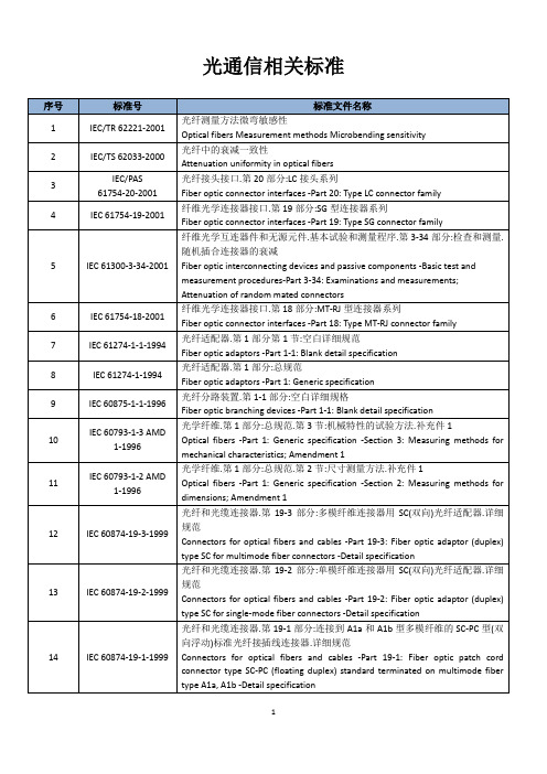
光通信相关标准序号标准号标准文件名称1 IEC/TR 62221-2001 光纤测量方法微弯敏感性Optical fibers Measurement methods Microbending sensitivity2 IEC/TS 62033-2000 光纤中的衰减一致性Attenuation uniformity in optical fibers3IEC/PAS61754-20-2001光纤接头接口.第20部分:LC接头系列Fiber optic connector interfaces -Part 20: Type LC connector family4 IEC 61754-19-2001 纤维光学连接器接口.第19部分:SG型连接器系列Fiber optic connector interfaces -Part 19: Type SG connector family5 IEC 61300-3-34-2001 纤维光学互连器件和无源元件.基本试验和测量程序.第3-34部分:检查和测量.随机插合连接器的衰减Fiber optic interconnecting devices and passive components -Basic test and measurement procedures-Part 3-34: Examinations and measurements; Attenuation of random mated connectors6 IEC 61754-18-2001 纤维光学连接器接口.第18部分:MT-RJ型连接器系列Fiber optic connector interfaces -Part 18: Type MT-RJ connector family7 IEC 61274-1-1-1994 光纤适配器.第1部分第1节:空白详细规范Fiber optic adaptors -Part 1-1: Blank detail specification8 IEC 61274-1-1994 光纤适配器.第1部分:总规范Fiber optic adaptors -Part 1: Generic specification9 IEC 60875-1-1-1996 光纤分路装置.第1-1部分:空白详细规格Fiber optic branching devices -Part 1-1: Blank detail specification10 IEC 60793-1-3 AMD1-1996光学纤维.第1部分:总规范.第3节:机械特性的试验方法.补充件1Optical fibers -Part 1: Generic specification -Section 3: Measuring methods formechanical characteristics; Amendment 111 IEC 60793-1-2 AMD1-1996光学纤维.第1部分:总规范.第2节:尺寸测量方法.补充件1Optical fibers -Part 1: Generic specification -Section 2: Measuring methods fordimensions; Amendment 112 IEC 60874-19-3-1999 光纤和光缆连接器.第19-3部分:多模纤维连接器用SC(双向)光纤适配器.详细规范Connectors for optical fibers and cables -Part 19-3: Fiber optic adaptor (duplex) type SC for multimode fiber connectors -Detail specification13 IEC 60874-19-2-1999 光纤和光缆连接器.第19-2部分:单模纤维连接器用SC(双向)光纤适配器.详细规范Connectors for optical fibers and cables -Part 19-2: Fiber optic adaptor (duplex) type SC for single-mode fiber connectors -Detail specification14 IEC 60874-19-1-1999 光纤和光缆连接器.第19-1部分:连接到A1a和A1b型多模纤维的SC-PC型(双向浮动)标准光纤接插线连接器.详细规范Connectors for optical fibers and cables -Part 19-1: Fiber optic patch cord connector type SC-PC (floating duplex) standard terminated on multimode fiber type A1a, A1b -Detail specification15 IEC 60874-19-1995 光纤和光缆连接器.第19部分:光纤连接器的分规范.SC-Duplex型Connectors for optical fibers and cables -Part 19: Sectional specification for fiber optic connector -Type SC-Duplex16 IEC 60874-14-3-1997 光纤和光缆连接器.第14-3部分:单模纤维用SC型光纤连接器的详细规范Connectors for optical fibers and cables -Part 14-3: Detail specification for fiber optic adaptor (simplex) type SC for single-mode fiber17 IEC 60874-14-1993 光纤和光缆连接器.第14部分:SC型光纤连接器的分规范Connectors for optical fibers and cables; part 14: sectional specification for fiber optic connector; type SC18 IEC 60874-7-1993 光纤和光缆连接器.第7部分:分规范.FC型光纤连接器Connectors for optical fibers and cables; part 7: sectional specification for fiber optic connector; type FC19 GB/T 15972.3—1998 光纤总规范第3部分机械性能试验方法20 GB/T 14137—93 光纤机械式固定接头插入损耗测试方法21 YD/T 1198-2002 光纤活动连接器插针体技术要求22 YD/T 1117-2001 全光纤型分支器件技术条件23 YD/T 925-1997 光缆终端盒24 YD/T 899-1997 双芯光缆25 YD/T 898-1997 单芯光缆26 YD/T 814-1996 光缆接头盒27 YD/T 778-1999 光纤配线架28 YD/T 1258.3-2003 室内光缆系列第三部分双芯光缆The series of indoor optical fiber cables part 3:dual-fiber optical cable 2003/0429 YD/T 816-2003 大芯径大数值孔径多模光纤Multimode optical fiber with large core diameter and large numerical aperture 2003/0430 YD/T 1258.1-2003 室内光缆系列第一部分总则The series of indoor optical ribre cables part 1:general 2003/0431 YD/T 1182-2002 2.5Gb/s DWDM用特定波长光发射模块技术条件Technical Conditions of The 2.5Gb/s Nominal Central Wavelength Optical Transmitter Modules Used in DWDM System 2002/0232 YD/T 1198-2002 光纤活动连接器插针体技术要求Technical requirement of ferrule for optical fiber connector2002/0633 YD/T 1200-2002 MU型单模光纤活动连接器技术条件Technical condition of the type of MU single-mode optical fiber connector 2002/0634 YD/T 1272.1-2003 光纤活动连接器第一部分LC型Optical fiber connector Part 1:type LC35 YD/T 1258.3-2003 室内光缆系列第三部分双芯光缆The series of indoor optical fiber cables part 3:dual-fiber optical cable36 YD/T 1258.2-2003 室内光缆系列第二部分单芯光缆The series of indoor optical fiber cables part 2:single-fiber optical cable37 YD/T 1258.4-2005 室内光缆系列第四部分多芯光缆38 YD/T 1258.5-2005 室内光缆系列第五部分光纤带光缆。
光纤通信Fiber-optic communications

3.1 调制变量
场调制:
由电磁波,微波通讯发展而来。分为振幅调制(AM),相位调制(PM), 频率调制(FM)。 相对困难: 1:光源要求性高。需要一个具有稳定的振幅,相位或者频率并且能够自由 变化调制的具有高度相干性的光源。 2:直接调制通常比较困难,需要额外的电光调制器。 3:检测器件要求高。(外差检测系统)
从端口形式上:T型,X型,星型,树形耦合器。 从传导模式上:单模耦合器,多模耦合器。
主要原理:
光纤溶拉,衍射,梯度折射率,滤波器,分束器等
光纤耦合
光纤通信
Fiber-optic communications
5. 光纤耦合器
1
技术发展
2
3 4 5
基本器件
光 调 制 复用技术
光纤耦合
光纤通信
Fiber-optic communications
光纤耦合
光纤通信
Fiber-optic communications
2.2 光纤
传递函数 响应时间与带 5
基本器件
光 调 制 复用技术
衰减函数
光纤耦合
光纤通信
Fiber-optic communications
2.2 光纤
传递函数 响应时间与带宽:
1
技术发展
2
2
3 4 5
基本器件
光 调 制 复用技术
光纤耦合
这个现象叫做光纤的模式色散
光纤通信
Fiber-optic communications
2.2 光纤 渐变型多模光纤:
相对折射率差Δ :用来描述折射率相对变化 数值孔径NA :用来描述光纤集光能力的大小 归一化频率V:用来描述光纤中传播模式 多模光纤中有不同模式的存在,具有不同的群速度。 把由不同速度造成的时延叫做光纤的响应时间
《fiber optic communication system》 《光纤通信系统》课件 CHAPTER5汇总
A optoelectronic repeater, called a regenerator, is nothing but a receivertransmitter pair that detects the incoming optical signal, recovers the electrical bit stream, and then converts it back into optical form by modulating an optical source. It performs three functions-reamplification, reshaping, and retiming (the 3Rs). Optical amplifiers amplify the optical bit stream directly without requiring conversion of the signal to the electric domain. The spacing L between regenerators or optical amplifiers, often called the repeater spacing, is a major design parameter simply because the system cost reduces as L increases. The bit rate-distance product, BL, is generally used as a measure of the system performance for point-to-point links.
5.1.1 Point-to-Point Links
CommScope 场地可安装光纤接口连接器指南 2说明书
Field installable connectors by CommScope offer flexible network solutions are ideal for campus environments where exact measurements are not possible, or when there’s a need for a fast repair to restore network connections. The factory pre-polished ferrule eliminates the need for polishing, adhesives, and crimping in the field—minimizing the potential for operator error and expensive connector scrap. Easy to use and quick to install, CommScope field installable connectors and tool kits are designed to simplify the termination process and enable you to terminate and move to your next project with minimal investment in time and cost. ·Fast to install·No requirement for pre-engineered lengths ·Eliminates unwanted slack storage ·Consistent and reliable terminations ·No epoxy, no polish, no crimp ·Reduces scrap and waste·Compatible with industry-leading splicersCommScope offers an extended line of field installable connectors and tool kits, including mechanical splice Qwik II and fusion splice-on Qwik-Fuse connectors. At CommScope, we know campus network solutions are not a one size fits all. You can trust in our products and team of experts to help add the flexibility you need to create a quality solution.IntroductionAdditional ResourcesProduct InformationInstallation Videos (760248225)* Field terminated fiber patch cords are not included in CommScope Extended System WarrantyCommScope Qwik-Fuse field installable connectorsThe CommScope Qwik-Fuse connectors are field installable, splice-on, fiber optic connectors, uniquely designed to provide easy-to-use fusion splicing connectivity. Qwik-Fuse connectors enable fast,low-loss and reliable fusion splicing connectivity in the field withoutQwik-Fuse connector kitsQwik-Fuse connector tool kits and accessoriesCommScope Qwik-Fuse connector tool kits are designed to facilitate fastand reliable connector terminations. The Qwik-Fuse TKit includes all necessary tools and supplies for cable preparation andtermination—providing great convenience to installers and contractors.In addition to all components in the tool kit, the Qwik-Fuse Installer TQwik-Fuse connector tool kits and accessoriesCommScope Qwik-Fuse MPO field installable connectorsCommScope pushes the boundaries of communicationstechnology with game-changing ideas and ground-breakingdiscoveries that spark profound human achievement.We collaborate with our customers and partners to design,create and build the world’s most advanced networks. It is ourpassion and commitment to identify the next opportunity andrealize a better tomorrow. Discover more at Visit our website or contact your local CommScope representative for more information.© 2020 CommScope, Inc. All rights reserved.All trademarks identified by ® or ™ are registered trademarks or trademarks, respectively, of CommScope, Inc. This document is for planning purposes only and is not intended to modify or supplement any specifications or warranties relating to CommScope products or services. CommScope is committed to the highest standards of business integrity and environmental sustainability with a number of CommScope’s facilities across the globe certified in accordance with international standards, including ISO 9001, TL 9000, and ISO 14001.。
光纤测温传感器安装指南
W INDING TEMPERATURE SENSOR INSTALLATION:G UIDELINE 1. IntroductionOne of the most common causes of fiber optic sensor systems failure is a faulty installation: to ensure proper sensor installation, this guideline should be read and followed carefully.Opsens offers a unique and easy method for installing fiber optic temperature sensors into power transformers. This method is based on Opsens all-dielectric fiber-optic TC connector and on its specially grooved key spacer.Because the all-dielectric fiber optic TC connector can be placed anywhere in the transformer, this method eliminates the cumbersome and hazardous operation of cable spooling and handling during installation.The specially grooved mounting disk, unique to Opsens, ensures full protection against mechanical stresses that often cause sensor damage when installed in the transformer key spacer. Because the sensor’s sensing tip is held loose in the groove (see figure 9 in the next section), it is much less exposed to the compressive stresses during the winding compression manufacturing step of the power transformer.Figure 1 : Tip of sensor with optional factory-installed mounting disk.The following guidelines cover the installation of the temperature sensors in the winding with or without the optional mounting disk.2. General overview of the TC connectivity solutionThe following figure shows the all dielectric TC connection schematic.Figure 2 : Overview of sensor installation in transformer tank showing theTC connectivity solution. Since the TC connection can be placed anywhere in the transformer, only short fiber optic cable lengh is needed: this avoids conveying and handling long spans of fiber-optic cable during sensor installation and reduces the chances of sensor damage.The following figures (3, 4 &5) show a typical installation in the power transformer winding.Figure 3 : Sensor installation.To the sensorFigure 4 : Typical TC connector installation:Figure 5 : Internal extension cable routing:3. Installing a standard sensorThis section gives some advice for installing a standard sensor (without the optional mounting disk) into a key spacer.The customer must prepare his own key spacers for installing the fiber optic sensor. A groove and two openings have to be made in the spacer. Figure 6 shows the recommended groove.appliedFigure 6 : Specifications to user for grooving a key spacer for a standardsensor.Opsens fiber optic protection tube has tiny venting holes to let air escape and let oil in. A first hole is located 38mm from the tip of the sensor. Do not let adhesive go into the hole: the hard adhesive can transfer too much stress on the optical fiber.Do not let adhesive go onto the tip either: during coil compression, a hard adhesive will transfer directly the pressure from the coil to the sensor tip. Make sure the sensor tip is snug but free to move inside the groove.Referring to Figure 6: the glue will spread along the groove by capillarity. Drill two holes approx 4-5 mm to stop the capillary action and to keep the glue from reaching either the tip or the first hole.The groove is kept tight at the tip to maximize heat transfer.The angle of the groove is chosen to ensure a smooth egress of the fiber optic cable so that there is no sharp turn in the fibre cable (minimum bending radius is 25 mm for 62.5 / 125 µm fiber).Do not let the sensor tip be crushed when compressing the coil. Minimum spacer thickness is 1.5 mm to give headroom for the 1.2 mm O.D. sensor tip. Example : for a 15 % coil compression ratio, using 1.6 mm thick spacer and the 1.2 mm O.D. sensor tip, the maximum allowable compression is (1.6 – 1.2) ÷ 1.6 =25 % which gives some tolerance to local variations and irregularities.4. Installing a sensor equipped with the optionalmounting diskAs an option to the regular sensor, Opsens can provide sensors with a factory-installed mounting disc at 12mm from the sensor tip.The customer must prepare its own key spacers for installing the fiber optic sensor. A groove and an opening have to be made in the spacer.Figure 7 : Example of a grooved key spacer.Figure 8 : Specifications to user for grooving a key spacer for a sensorequipped with the optional mounting disk.The fiber optic temperature sensors provided by Opsens can be ordered with a mounting disc. This disc, mounted of the sensor fiber-optic cable, is inserted into the round opening of the grooved key spacer as shown on figure 9. Since the disc is held tight into the opening,there is no need for using adhesive. Epoxy or white glue can be used though to facilitate handling of the spacer/sensor assembly during insertion in the winding. The disk is 2 mm thick, so the minimum spacer thickness must also be 2 mm.The following figures show the assembly procedures of the fiber optic sensor into the grooved key spacer.Figure 9 : Installation steps for sensor equipped with optional mountingdisk.5.Installing into the transformer windingFigure 10 shows the sensor installation schematic into the transformer’s windings.Mounting discSensor tip1234installation:y Avoid sharp radius turns with the fiber-optic cable.y Respect specified minimum bending radius for the sensor and cable : 18 mm for 62.5/125 µm fiber (25 mm preferable).y Avoid tensioning or twisting the fiber-optic cabley Avoid pinch points and “scissors” when setting the sensors in placey Do not pull on fiber-optic cable to clear tangles; carefully unwind insteady Avoid dropping or scraping fiber-optic connectors on hard surfacesy Keep the surface of the fiber-optic connector very, very cleany Use the supplied fiber optic connector cleaner liberally, before and after each and every connection。
SOURIAU ARINC 801 Termini和38999连接器产品介绍说明书
ARINC 801 Fiber Optic ConnectorsARINC 801Termini and 38999 ConnectorsQuality and service100% SOURIAU components: termini,patchcord and connectors.The high density fiber optic connection made by SOURIAU using 1.25mm ferrules.Wide range of materialFrom composite, aluminum, to stainless steel material connectors in stock.A qualified technology Flight proven qualified ARINC 801 standard.Description• Screw coupling • Shell size from 11 to 25• Large number of layouts from 2 to 32 termini • Composite, aluminum, stainless steel material • Protected by cadmium, nickel, green zinc cobalt or black zinc nickel plating• Accessories and tools available (protective caps,backshells, etc… )Optical• Multimode insertion loss (IEC 61300-3-4 method B): Typical 0.3 dBMechanical• Endurance:Minimum 100 mating/unmating operations • Shock:300 g, 3ms as per TIA/EIA 455-14• Vibration:23.1 Grms as per TIA/EIA 455-11• Contact retention:68N, as per SAE AS 13441 method 2009.1 for 1.8mm cableEnvironmental• Salt spray:. Aluminum shell:Olive Drab Cadmium (W): 500 Hrs Nickel (F): 48 HrsBlack Zinc Nickel (Z): 500 Hrs . Composite shell:Olive Drab Cadmium (J): 2000 Hrs Nickel (M): 2000 HrsWithout plating (X): 2000 Hrs . Stainless steel shell:Passivated (K): 500 Hrs Nickel (S): 500 Hrs• Temperature range:. Thermal cycling 50 cycles between -55°C to +125°C as per TIA/EIA 455-3. Temperature life 1000 hours at 125°C as per TIA/EIA-455-4C• Humidity:10 cycles/24h, -25 to +65°C, 90% RH as per TIA/EIA 455-5• Altitude immersionPressure equivalent to 50,000 ft (15,200 m)Technical featuresNote: All dimensions are in millimeters (mm)Termini8.13 Max.12.3 Max. after crimping14.2 Min. forward positionØ2.25 M a Ø3.40 M a Ø2.75 M a Protective capFerruleOrdering informationSOURIAU ARINC 801 TerminiARC1G18TAFiber type:G: Multimode fiber 50/125μm or 62.5/125μmE: Singlemode fiber 9/125μm - consult us for availability Cable type and diameter:09T: Ø 900μm fiber cable - non waterproof18T: Ø 1.6mm to Ø 2.2mm fiber cable, tight structure 18L: Ø 1.6mm to Ø 2.2mm fiber cable, loose structure Contact version indexConnectorOrdering information8D Connector8D5U25F32BNShell type:0: Square flange receptacle (male insert only) 5: Plug (female insert only) 7: Jam nut receptacle (male insert only) U: ARINC 801 optical connectorShell size: 11, 13, 15, 17, 19, 21, 23, 25 Material and plating:Aluminum:W: Olive green cadmium F: NickelZ: Zinc Nickel Stainless steel: K: Passivated S: NickelComposite:J: Olive green cadmium M: NickelX: Without platingLayout: See below Insert gender:A: Male B: FemaleOrientation: N, A, B, C, D, ELayoutsSleeve holder front view* Please consult us for availability.SOURIAU offers a wide range of cables, from cost efficient to high performance aeronautical cables.Select your optical fiber’s properties. Temperature range can be critical for your applications.If you need any help on a criteria selection, please contact us.* 1st value @850nm for multimode cable, 2nd value @1300nm for multimode (respectivly 1300nm and 1550nm for singlemode)Consult us for other harsh environment cables.1 Select CableOrdering informationPatchcord LengthPatchcord Cable/Terminus Combination CodePatchcord - Your optical patchcord in 3 steps!W D S A R I N C 801W U S E N 03 © C o p y r i g h t S O U R I A U J u l y 2020 - S O U R I A U i s a r e g i s t e r e d t r a d e m a r k .A l l i n f o r m a t i o n i n t h i s d o c u m e n t p r e s e n t s o n l y g e n e r a l p a r t i c u l a r s a n d s h a l l n o t f o r m p a r t o f a n y c o n t r a c t . A l l r i g h t s r e s e r v e d t o S O U R I A U f o r c h a n g e s w i t h o u t p r i o r n o t i fi c a t i o n o r p u b l i c a n n o u n c e m e n t . A n y d u p l i c a t i o n i s p r o h i b i t e d , u n l e s s a p p r o v e d i n w r i t i n g .Tooling and accessories2 Select Termini End 1 & 2 according to your selected cable,and get your finalPatchcord Cable/Terminus Combination CodeMost common cables with most common contacts - For other combinations please consult us.All contacts are UPC polished otherwise specified.M81969/14-03ARINC 801 adaptor for LC polishing and measuringLC Adaptor + ARINC 801 termini= LC compatible interfacePart Number: ALC1 (contact us for availability)For further information contact us at technical.emear @ (Europe - Asia - Africa)technical.americas @ (North America)or visit our web site 。
- 1、下载文档前请自行甄别文档内容的完整性,平台不提供额外的编辑、内容补充、找答案等附加服务。
- 2、"仅部分预览"的文档,不可在线预览部分如存在完整性等问题,可反馈申请退款(可完整预览的文档不适用该条件!)。
- 3、如文档侵犯您的权益,请联系客服反馈,我们会尽快为您处理(人工客服工作时间:9:00-18:30)。
Fiber optic connectorsThe fiber optic connectors is the removable (active) device connected between the fiber optical cables, make the two optical fiber end face precision to dock, so that the output light energy of transmitter optical cable can be maximize coupling to the receiving fiber cable. And make sure its impact can be minimized because of its involvement in the optical link system , which is the basic requirements for fiber optic connectors. To a certain extent, fiber optic connectors also affected the reliability and the performance of fiber optical transmission systems.Fiber optic connector according to the different transmission media can be divided into common silicon-based optical fiber single-mode and multimode connectors, as well as other issues such as plastic and as the transmission medium of optical fiber connector; connector structure can be divided into: FC,SC, ST, LC, D4, DIN, MU, the MT and so on . The ST connector is usually usedconnector typically used for network equipment side. Fiber end shape in the FC, PC (including SPC or UPC) and APC; divided by the number of the fiber core as well as single and multi-core(such as MT-RJ) points. Fiber optic connectors are widely used variety. In practical applications, we generally in accordance with the different structure of the fiber optic connector to be distinguished.The Fiber optic connectors typesaccording to the different transmission media can be divided into common silicon-based optical fiber single-mode and multimode connectors, as well as other issues such as plastic and as the transmission medium of optical fiber connector; connector structure can be divided into: FC SC, ST, LC, D4, DIN, MU, the MT and so on in various forms.1) FC fiber optic connector .This connection was first developed by NTT. FC is abbreviation of Ferrule Connector. Its external strengthen is metal sleeve, fastening by the turnbuckle. The earliest, FC type connectors were usedin ceramic pin docking port. Such connector structure is simple, easy to operate, easy production. However, the fiber end face is more sensitive to dust, and prone to Fresnel reflection, is more difficult to improve return loss performance. Later, this type of connector have some improvements: using the butt end leaving spherical pin (PC), while the external structure is not changed, making the insertion loss and return loss performance has been dramatically increased.(2) SC fiber optic connectors.This is also developed by Japan's NTT fiber optic connectors. The shell is rectangular, used in the structure of the pin and coupling sleeve size, exactly same with the FC type. Pins of end use of the PC or APC polishing; fastening method is using of the plug pin latch without rotation. Such connectors are inexpensive, easy to operate, plug, involved in the loss volatility, higher compressive strength and high density mounting.ST and SC connector are two types of fiber optic connectors. For 10Base-F connection, the connector is usually ST type ;For 100Base-FX usually IS SC type connector. The core of the ST connectorexposed and the SC’core is inside of the connector.(3) the biconical connectorThe most representative products in the fiber optic connectors category, developed by the U.S. Bell Labs, it was composed by the two ends of precision molding forming truncated conical cylinder plug and an in-house is equipped with dual cone-shaped plastic sleeve tube coupling components.(4) DIN47256 optical fiber connectorThis is a German-developed connector. This connection uses the structure of the pin and coupling sleeve size same with FC.PC polishing end processing. Compared with FC connector, its structure is more complex, the internal metal structure with spring to control the pressure to avoid docking excessive pressure damage face. In addition, this connector with high mechanical precision, and thus less involved in the value loss.(5) MT-RJ connectorMT-RJ, MT started in the development of NTT connectors with the same RJ-45 LAN power connector latch body, align the optical fiber installed in a small casing on both sides of the guide pin, a letter for easy and light transceiver The machine is connected to the connector end fiber for dual-core (intervals 0.75mm) arranged in the design, is used mainly for data transmission, the next generation of high-density fiber optic connectors.LC-type connector is made of the famous Bell Institute of Research and Development, and easy to operate modular jack (RJ) latch mechanism. Their use of pin and sleeve size is half of the ordinary, SC,application of multimode have rapid growth.(7) Type MU connectorMU (Miniature unit Coupling) connector is based on the currently most used SC connector. It is world's smallest single-core optical fiber connector developed by NTT. The connector with 1.25mm diametercasing and self-sustaining institutions, its advantage lies in its ability to achieve high-density mounting. MU's l.25mm diameter casing, NTT has developed the MU connector family. They have a socket-type connector for fiber optic cables (MU-series); from the backplane connector (MU-B series) and maintain institutions for simplified connection of LD / PD module and plug socket (MU-SR Series) and so on. With the rapid development of fiber-optic network to the greater capacity and greaterrapidly.。