r-Dynamic Simulation-Assignment Model (DynaTAIWAN) Under Mixed Traffic Flows for ITS Applications
电气工程及其自动化毕业论文_利用MATLAB的动态仿真软件Simulink搭建了单机—无穷大电力系统的仿真模型

摘要电力工业迅速发展,电力系统规模日益庞大和复杂,出现的各种故障,会给发电厂以及用户和电厂内的多种动力设备的安全带来威胁,并有可能导致电力系统事故的扩大,从技术和安全上考虑直接进行电力试验可能性很小,迫切要求运用电力仿真来解决这些问题,依据电网用电供电系统电路模型要求,因此,论文利用MATLAB的动态仿真软件Simulink搭建了单机—无穷大电力系统的仿真模型,能够满足电网可能遇到的多种故障方面运行的需要。
论文以MATLAB R2009b电力系统工具箱为平台,通过SimPowerSyetem搭建了电力系统运行中常见的单机—无穷大系统模型,设计得到了在该系统发生各种短路接地故障并故障切除的仿真结果。
本文做的主要工作有:(1)Simulink下单机—无穷大仿真系统的搭建(2)系统故障仿真测试分析通过实例说明,若将该方法应用到电力系统短路故障的诊断中,快速实现故障的自动诊断、检测,对于提高电力系统的稳定性具有十分重要的意义。
关键词电力系统;暂态稳定;MATLAB;单机—无穷大;AbstractWith the rapid development of power industry,the scale of power system is increasingly large and complex,all kinds of fault,to power plants and power plants and users in a variety of power equipment safety threat,and is likely to lead to the expansion of power system accident,from the technical and safety considering direct electricity experiment was carried out on the possibility is very small,urge electric power simulation are used to solve these problems,according to the power supply system of power grid power circuit model,as a result,paper use MATLAB dynamic simulation software Simulink has set up a simulation model for the single-infinite power system,can satisfy the needs of the running of a fault may encounter a variety of ways.Paper R2009b with MATLAB toolbox power system as a platform,through SimPowerSyetem set up power system in the operation of the common single-infinity system model,design the various kinds of short-circuit ground fault occurs in the system and simulation results of fault removed.The main work is:(1)Building this simulation system of single-infinite under Simulink(2)Fault simulation test analysis of systemThrough examples,if this method to the power system fault diagnosis,fast fault detection and diagnosis,automatic for improving the stability of power system has important significance.keywords:Single—infinite;SimPowerSyetem;Short circuit faults;Wavelettransform目录绪论 (1)第一章电力系统稳定性概述 (1)1.1电力系统的静态稳定性 (1)1.2电力系统的暂态稳定性 (1)第二章基于MATLAB的电力系统仿真 (3)2.1电力系统稳定运行的控制 (3)2.2MATLAB及SimPowerSystem简介 (3)2.3配电网的故障现状及分析 (4)2.4暂态稳定仿真流程 (5)第三章单机—无穷大暂态稳定仿真分析 (5)3.1电力系统暂态稳定性分析 (6)3.1.1引起电力系统大扰动的原因 (6)3.1.2定性分析 (6)3.1.3提高电力系统稳定性的措施 (8)3.2单机—无穷大系统原理 (9)第四章Simulink下SimPowerSystem模型应用 (12)4.1仿真模型的搭建 (12)4.2运行效果仿真图 (13)4.2.1改变故障模块中的短路类型 (13)4.2.2改变系统中的元件参数(改变线路的电阻) (17)4.3加入电容补偿器后的的仿真图 (18)4.4小结 (22)第五章结论和展望 (22)参考文献 (24)致谢 (25)绪论随着电力系统规模不断扩大,系统发生故障的影响也越来越大,尤其大区域联网背景下的电力系统故障将会给经济、社会造成重大经济损失,因此保证电力系统安全稳定运行是电力生产的首要任务。
r语言 dcc导出条件相关系数 -回复

r语言dcc导出条件相关系数-回复R语言中的DCC模型(Dynamic Conditional Correlation Model)是一种用于估计条件相关系数的统计模型。
条件相关系数是衡量不同变量之间相关性水平的指标,它反映了变量之间的关联程度,对于金融领域中的资产组合管理、风险控制和投资决策具有重要意义。
在这篇文章中,我将详细介绍如何在R语言中使用DCC模型导出条件相关系数。
首先,我们需要安装并加载"rmgarch"包,它是一个用于金融时间序列建模和预测的R包。
你可以使用下面的代码安装该包:Rinstall.packages("rmgarch")library(rmgarch)接下来,我们需要准备数据。
DCC模型需要一个时间序列数据集,其中包含多个变量的观测值。
假设我们有一个包含三个变量(A、B和C)的数据集,可以使用以下代码加载数据:Rdata <- read.csv("data.csv")我们可以使用以下代码查看数据集的结构和前几行观测值:Rstr(data)head(data)接下来,我们需要创建一个rmgarch对象来拟合DCC模型。
我们可以使用以下代码来创建对象:Rspec <- dccspec(uspec = multispec(replicate(3,ugarchspec(variance.model = list(model = "sGARCH")), simplify = FALSE)), dccOrder = c(1, 1), distribution = "mvnorm")在上述代码中,我们使用了multispec函数来创建一个包含三个同质的GARCH模型的列表,每个模型用于估计单个变量的方差。
我们将这个列表作为参数传递给dccspec函数来创建一个多变量GARCH模型。
Simulink模块库学习笔记

Simulink模块库简介0 修改历史1、连续模块(continuous)(1)Derivative输入信号微分;(2)Integrator输入信号积分;(3)State-Space状态空间系统模型(4)Transfer-Fcn传递函数模型(5)TransportDelay输入信号延时一个固定时间再输出(6)VariableTransportDelay输入信号延时一个可变时间再输出(7)Zero-Ploe零极点模型2、非连续模块(Discontinuous)(1)Backlash间隙非线性(2)Coulomb&ViscousFriction库仑和粘度摩擦非线性(3)DeadZone死区非线性(4)DeadZoneDynamic动态死区非线性(5)HitCrossing冲击非线性(6)Quantizer量化非线性(7)RateLimiter静态限制信号的变化速率(8)RateLimiterDynamic动态限制信号的变化速率(9)Relay滞环比较器,限制输出值在某一范围内变化(10)Saturation饱和输出,让输出超过某一值是能够饱和(11)SaturationDynamic动态饱和输出(12)WrapToZero3、离散模块(Discrete)(1)Difference差分环节(2)DiscreteDerivative离散微分环节(3)DiscreteFilter离散滤波器(4)DiscreteState-Space离散状态空间系统模型(5)DiscreteTransferFcn离散传递函数模型(6)DiscreteZero-Pole以零极点表示的离散传递函数模型(7)Discrete-TimeIntegrator离散时间积分器(8)First-OrderHold一阶保持器(9)IntegerDelay整数被延迟(10)Memory输出本模块上一步的输入值(11)TappedDelay延迟(12)TransferFcnFirstOrder离散一阶传递函数(13)TransferFcnLeadorLag传递函数(14)TransferFcnRealZero离散零点传递函数(15)UnitDelay一个采样周期的延时(16)WeightedMovingAverage权值移动平均模型(17)Zero-OrderHold零阶保持器4、逻辑和位操作模块(LogicandBitOperation)(1)BitClear位清零输入的数指定位清零请参考(3)的示例图。
-rdynamic参数解释

-rdynamic参数解释
`-rdynamic` 是一个GCC编译器选项,它告诉编译器生成动态链接库时把所有符号都
导出到动态符号表中。
这个选项的作用是在程序启动后让动态链接库可以被其他程序使用。
如果不使用这个选项,则编译器只会导出动态链接库中的公共符号,也就是可以被其他程
序使用的符号。
一般来说,使用 `-rdynamic` 选项编译动态链接库时需要使用 `--export-dynamic` 选项来告诉链接器将所有符号导出到动态符号表中。
这样就可以在程序启动时将动态链接
库加载进来使用了。
使用 `-rdynamic` 选项的好处是可以让我们在程序运行时动态加载动态链接库,而
不需要提前知道需要加载哪些库。
这对于一些根据用户输入动态加载模块的程序来说非常
有用。
如果程序在运行时需要加载某个模块,就可以通过动态链接库的方式加载进来,而
不需要重新编译和链接整个程序。
需要注意的是,使用 `-rdynamic` 选项编译程序会增加程序的大小,因为会将所有
符号都导出到动态符号表中。
因此,如果程序中确实需要使用动态链接库,才需要使用此
选项。
另外,不同的平台对 `-rdynamic` 的支持也有所不同。
在一些平台上,这个选项可
能会被忽略,或者需要通过其他方式来实现动态链接库的导出。
因此,在使用这个选项时
需要注意平台的支持情况。
汽车动态系统仿真模型验证方法综述
22AUTO TIMEFRONTIER DISCUSSION | 前沿探讨汽车动态系统仿真模型验证方法综述廖卓 赵橄培 罗龙健湖南汽车工程职业学院 湖南省株洲市 412000摘 要: 仿真模型是人们开展各类科学研究的重要工具,其自身的可信度将直接影响仿真运行结果的可靠性,而模型验证则是评价仿真模型可信度的主要方法。
基于此,本文综述了汽车动态系统仿真模型相关概念及模型验证方法发展历程,根据汽车安全领域仿真模型的特点,重点对时域分析方向已有的模型验证方法进行了分类,并对相应的模型验证辅助工具存在的问题进行了梳理,提出了未来的重点研究方向。
关键词:汽车安全 仿真技术 动态系统 模型验证1 前言数字化建模与仿真技术已完成为人们开展各类研究的重要手段,尤其在汽车被动安全研究领域的地位更为突出,正因为仿真技术的重要作用,仿真模型的可信度必然备受用户关注,模型的可信度将直接影响仿真结果的准确性和实用价值,因此,针对仿真模型,尤其是复杂动态系统仿真模型的验证方法及相关辅助工具的研究逐渐成为国内外研究热点。
本文旨在综述汽车动态系统仿真模型验证方法的研究进展,梳理现阶段模型验证工具存在的问题,指出其未来发展方向。
2 汽车动态系统仿真模型及模型验证2.1 汽车动态系统仿真模型数字化仿真已经成为新车开发过程中必不可少的一部分,更是汽车被动安全研究领域的主要方式之一。
汽车被动安全领域的汽车碰撞过程(如图1所示),是一个具有高度非线性和复杂性的动态过程,该过程中包含的车、人和物(道路安全设施)等相关环境共同组成汽车动态系统。
在针对此类汽车动态系统进行碰撞研究分析时,一方面需要关注动态系统输出响应数据之间高度的时间相关性和时变性,同时需要将其相位、幅度及频率等曲线特征差异也纳入监控范围,另一方面动态系统通常包含多个输出响应,且响应间存在着很强的相关性,因而需要建立可信的汽车动态系统仿真模型进行研究分析。
图1 汽车碰撞过程2.2 仿真模型验证方法发展历程仿真模型本身的可信度会直接影响应用该模型研究所得结果的准确性,尤其是汽车动态系统等具有复杂运行机理和交互关系的仿真模型,其内部缺陷和错误不易被发现,若不对其进行验证,将会给模型应用带来巨大的风险。
abaqus结构分析单元类型

a b a q u s结构分析单元类型(总5页)--本页仅作为文档封面,使用时请直接删除即可----内页可以根据需求调整合适字体及大小--;this wordfile adds the code folding function which is useful to ignore rows of numbers,enjoy~;updated in , based on the wordfile "abaqus_67ef()";Syntax file for abaqus keywords ,code folding enabled;add *ANISOTROPIC *ENRICHMENT *LOW -DISPLACEMENT HYPERELASTIC;newly add /C"ElementType";delete DISPLACEMENT;delete MASS in /C2"Keywords2"/L29"abaqus_612" Nocase File Extensions = inp des dat msg/Delimiters = ~!@$%^&()_-+=|\/{}[]:;"'<> ,.//Function String = "%[ ^t]++[ps][a-z]+ [a-z0-9]+ ^(*(*)^)*{$"/Function String 1 = "%[ ^t]++[ps][a-z]+ [a-z0-9]+ ^(*(*)^)[ ^t]++$" /Member String = "^([A-Za-z0-9_:.]+^)[ ^t*&]+$S[ ^t]++[(=);,]"/Variable String = "^([A-Za-z0-9_:.]+^)[ ^t*&]+$S[ ^t]++[(=);,]"/Open Fold Strings = "*" "**""***"/Close Fold Strings = "*" "**""***"/C1"Keywords1" STYLE_KEYWORD*ACOUSTIC *ADAPTIVE *AMPLITUDE *ANISOTROPIC *ANNEAL *AQUA *ASSEMBLY *ASYMMETRIC *AXIAL *BASE *BASELINE *BEAM*BIAXIAL *BLOCKAGE *BOND *BOUNDARY *BRITTLE *BUCKLE *BUCKLING *BULK *C *CAP *CAPACITY *CAST *CAVITY *CECHARGE*CECURRENT *CENTROID *CFILM *CFLOW *CFLUX *CHANGE *CLAY *CLEARANCE*CLOAD *CO *COHESIVE *COMBINED *COMPLEX*CONCRETE *CONDUCTIVITY *CONNECTOR *CONSTRAINT *CONTACT *CONTOUR*CONTROLS *CORRELATION *COUPLED *COUPLING*CRADIATE *CREEP *CRUSHABLE *CYCLED *CYCLIC *D *DAMAGE *DAMPING*DASHPOT *DEBOND *DECHARGE *DECURRENT*DEFORMATION *DENSITY *DEPVAR *DESIGN *DETONATION *DFLOW *DFLUX*DIAGNOSTICS *DIELECTRIC *DIFFUSIVITY*DIRECT *DISPLAY *DISTRIBUTING *DISTRIBUTION *DLOAD *DRAG *DRUCKER*DSA *DSECHARGE *DSECURRENT *DSFLOW*DSFLUX *DSLOAD *DYNAMIC *EL *ELASTIC *ELCOPY *ELECTRICAL *ELEMENT*ELGEN *ELSET *EMBEDDED *EMISSIVITY*END *ENERGY *ENRICHMENT *EOS *EPJOINT *EQUATION *EULERIAN *EXPANSION *EXTREME *FABRIC *FAIL *FAILURE*FASTENER *FIELD *FILE *FILM *FILTER *FIXED *FLOW *FLUID *FOUNDATION *FRACTURE *FRAME *FREQUENCY *FRICTION*GAP *GASKET *GEL *GEOSTATIC *GLOBAL *HEADING *HEAT *HEATCAP*HOURGLASS *HYPERELASTIC *HYPERFOAM *HYPOELASTIC*HYSTERESIS *IMPEDANCE *IMPERFECTION *IMPORT *INCIDENT *INCLUDE*INCREMENTATION *INELASTIC *INERTIA*INITIAL *INSTANCE *INTEGRATED *INTERACTION *INTERFACE *ITS *JOINT*JOINTED *JOULE *KAPPA *KINEMATIC*LATENT *LOAD *LOADING *LOW *M1 *M2 *MAP *MASS *MATERIAL *MATRIX*MEMBRANE *MODAL *MODEL *MOHR *MOISTURE*MOLECULAR *MONITOR *MOTION *MPC *MULLINS *NCOPY *NFILL *NGEN *NMAP *NO *NODAL *NODE *NONSTRUCTURAL*NORMAL *NSET *ORIENTATION *ORNL *OUTPUT *PARAMETER *PART *PERIODIC *PERMEABILITY *PHYSICAL *PIEZOELECTRIC*PIPE *PLANAR *PLASTIC *POROUS *POST *POTENTIAL *PRE *PREPRINT*PRESSURE *PRESTRESS *PRINT *PSD *RADIATE*RADIATION *RANDOM *RATE *RATIOS *REBAR *REFLECTION *RELEASE*RESPONSE *RESTART *RETAINED *RIGID *ROTARY*SECTION *SELECT *SFILM *SFLOW *SHEAR *SHELL *SIMPEDANCE *SIMPLE*SLIDE *SLOAD *SOILS *SOLID *SOLUBILITY*SOLUTION *SOLVER *SORPTION *SPECIFIC *SPECTRUM *SPRING *SRADIATE*STATIC *STEADY *STEP *SUBMODEL*SUBSTRUCTURE *SURFACE *SWELLING *SYMMETRIC *SYSTEM *TEMPERATURE*TENSILE *TENSION *THERMAL *TIE *TIME*TORQUE *TRACER *TRANSFORM *TRANSPORT *TRANSVERSE *TRIAXIAL *TRS *UEL *UNDEX *UNIAXIAL *UNLOADING *USER*VARIABLE *VIEWFACTOR *VISCO *VISCOELASTIC *VISCOUS *VOID *VOLUMETRIC *WAVE *WIND-AXISYMMETRIC -DEFINITION -DISPLACEMENT -SIMULATION -SOIL -TENSION/C2"Keywords2"ACTIVATION ADDED AREA ASSEMBLE ASSEMBLY ASSIGNMENT AXIALBEHAVIOR BODY BULKCASE CAVITY CENTER CHAIN CHANGE CHARGE CLEARANCE COMPACTION COMPONENT COMPRESSION CONDITIONS CONDUCTANCECONDUCTIVITY CONSTANTS CONSTITUTIVE CONSTRAINT CONTACT CONTROL CONTROLS COPY CORRECTION COULOMB COUPLINGCRACKING CREEP CRITERIA CRITERION CYCLICDAMAGE DAMAGED DAMPING DATA DEFINED DEFINITION DELETE DENSITY DEPENDENCE DEPENDENT DERIVED DETECTIONDIFFUSION DIRECTORY DOFS DYNAMIC DYNAMICSEFFECT EIGENMODES ELASTIC ELASTICITY ELECTRICAL ELEMENT ELSET ENVELOPE EVOLUTION EXCHANGE EXCLUSIONSEXPANSIONFACTORS FAILURE FIELD FILE FLAW FLOW FLUID FLUX FOAM FORMAT FORMULATION FRACTION FREQUENCY FRICTIONGENERAL GENERATE GENERATION GRADIENTHARDENING HEAT HOLD HYPERELASTICINCLUSIONS INERTIA INFLATOR INITIATION INPUT INSTANCE INTEGRAL INTERACTION INTERFERENCE IRONLAYER LEAKOFF LENGTH LINE LINK LOAD LOCKM1 M2 MATERIAL MATRIX MEDIUM MESH METAL MIXTURE MODEL MODES MODULI MODULUS MOTIONNODAL NODE NSET NUCLEATIONORIGIN OUTPUTPAIR PARAMETER PART PARTICLE PATH PENETRATION PLASTIC PLASTICITY POINT POINTS POTENTIAL PRAGER PRINTPROPERTYRADIATION RATE RATIOS REDUCTION REFERENCE REFLECTION REGION RELIEF RESPONSE RESULTS RETENTIONSECTION SCALING SHAPE SHEAR SOLID SOLUTION SPECTRUM STABILIZATION STATE STEP STIFFENING STIFFNESS STOPSTRAIN STRESS SURFACE SWELLING SYMMETRYTABLE TECHNIQUE TEMPERATURE TENSION TEST THERMAL THICKNESS TO TORQUE TRANSFER TRANSPORTVALUE VARIABLES VARIATION VELOCITY VIEWFACTOR VISCOSITYWAVE WEIGHT/C3"ElementType" STYLE_ELEMENTAC1D2 AC1D3 AC2D3 AC2D4 AC2D4R AC2D6 AC2D8 AC3D4 AC3D6 AC3D8 AC3D8R AC3D10 AC3D15 AC3D20 ACAX3 ACAX4ACAX4R ACAX6 ACAX8 ACIN2D2 ACIN2D3 ACIN3D3 ACIN3D4 ACIN3D6 ACIN3D8 ACINAX2 ACINAX3 ASI1 ASI2 ASI2AASI2D2 ASI2D3 ASI3 ASI3A ASI3D3 ASI3D4 ASI3D6 ASI3D8 ASI4 ASI8 ASIAX2 ASIAX3B21 B21H B22 B22H B23 B23H B31 B31H B31OS B31OSH B32 B32H B32OSB32OSH B33 B33HC3D4 C3D4E C3D4H C3D4P C3D4T C3D6 C3D6E C3D6H C3D6P C3D6T C3D8 C3D8E C3D8H C3D8HT C3D8I C3D8IH C3D8PC3D8PH C3D8PHT C3D8PT C3D8R C3D8RH C3D8RHT C3D8RP C3D8RPH C3D8RPHTC3D8RPT C3D8RT C3D8T C3D10 C3D10EC3D10H C3D10I C3D10M C3D10MH C3D10MHT C3D10MP C3D10MPH C3D10MPTC3D10MT C3D15 C3D15E C3D15H C3D15VC3D15VH C3D20 C3D20E C3D20H C3D20HT C3D20P C3D20PH C3D20R C3D20REC3D20RH C3D20RHT C3D20RP C3D20RPHC3D20RT C3D20T C3D27 C3D27H C3D27R C3D27RH CAX3 CAX3E CAX3H CAX3T CAX4 CAX4E CAX4H CAX4HT CAX4ICAX4IH CAX4P CAX4PH CAX4PT CAX4R CAX4RH CAX4RHT CAX4RP CAX4RPHCAX4RPHT CAX4RPT CAX4RT CAX4T CAX6CAX6E CAX6H CAX6M CAX6MH CAX6MHT CAX6MP CAX6MPH CAX6MT CAX8 CAX8E CAX8H CAX8HT CAX8P CAX8PH CAX8RCAX8RE CAX8RH CAX8RHT CAX8RP CAX8RPH CAX8RT CAX8T CAXA4HN CAXA4N CAXA4RHN CAXA4RN CAXA8HN CAXA8NCAXA8PN CAXA8RHN CAXA8RN CAXA8RPN CCL12 CCL12H CCL18 CCL18H CCL24 CCL24H CCL24R CCL24RH CCL9 CCL9HCGAX3 CGAX3H CGAX3HT CGAX3T CGAX4 CGAX4H CGAX4HT CGAX4R CGAX4RH CGAX4RHT CGAX4RT CGAX4T CGAX6 CGAX6HCGAX6M CGAX6MH CGAX6MHT CGAX6MT CGAX8 CGAX8H CGAX8HT CGAX8R CGAX8RH CGAX8RHT CGAX8RT CGAX8T CIN3D12RCIN3D18R CIN3D8 CINAX4 CINAX5R CINPE4 CINPE5R CINPS4 CINPS5R COH2D4 COH2D4P COH3D6 COH3D6P COH3D8COH3D8P COHAX4 COHAX4P CONN2D2 CONN3D2 CPE3 CPE3E CPE3H CPE3T CPE4 CPE4E CPE4H CPE4HT CPE4I CPE4IHCPE4P CPE4PH CPE4R CPE4RH CPE4RHT CPE4RP CPE4RPH CPE4RT CPE4T CPE6 CPE6E CPE6H CPE6M CPE6MH CPE6MHTCPE6MP CPE6MPH CPE6MT CPE8 CPE8E CPE8H CPE8HT CPE8P CPE8PH CPE8RCPE8RE CPE8RH CPE8RHT CPE8RPCPE8RPH CPE8RT CPE8T CPEG3 CPEG3H CPEG3HT CPEG3T CPEG4 CPEG4H CPEG4HT CPEG4I CPEG4IH CPEG4R CPEG4RHCPEG4RHT CPEG4RT CPEG4T CPEG6 CPEG6H CPEG6M CPEG6MH CPEG6MHT CPEG6MT CPEG8 CPEG8H CPEG8HT CPEG8RCPEG8RH CPEG8RHT CPEG8T CPS3 CPS3E CPS3T CPS4 CPS4E CPS4I CPS4RCPS4RT CPS4T CPS6 CPS6E CPS6M CPS6MTCPS8 CPS8E CPS8R CPS8RE CPS8RT CPS8TDASHPOT1 DASHPOT2 DASHPOTA DC1D2 DC1D2E DC1D3 DC1D3E DC2D3 DC2D3EDC2D4 DC2D4E DC2D6 DC2D6E DC2D8DC2D8E DC3D10 DC3D10E DC3D15 DC3D15E DC3D20 DC3D20E DC3D4 DC3D4EDC3D6 DC3D6E DC3D8 DC3D8E DCAX3DCAX3E DCAX4 DCAX4E DCAX6 DCAX6E DCAX8 DCAX8E DCC1D2 DCC1D2D DCC2D4 DCC2D4D DCC3D8 DCC3D8D DCCAX2DCCAX2D DCCAX4 DCCAX4D DCOUP2D DCOUP3D DGAP DRAG2D DRAG3D DS3 DS4 DS6 DS8 DSAX1 DSAX2EC3D8R EC3D8RT ELBOW31 ELBOW31B ELBOW31C ELBOW32 EMC2D3 EMC2D4 EMC3D4 EMC3D8F2D2 F3D3 F3D4 FAX2 FLINK FRAME2D FRAME3D FC3D4 FC3D6 FC3D8GAPCYL GAPSPHER GAPUNI GAPUNIT GK2D2 GK2D2N GK3D12M GK3D12MN GK3D18 GK3D18N GK3D2 GK3D2N GK3D4LGK3D4LN GK3D6 GK3D6L GK3D6LN GK3D6N GK3D8 GK3D8N GKAX2 GKAX2N GKAX4 GKAX4N GKAX6 GKAX6N GKPE4 GKPE6GKPS4 GKPS4N GKPS6 GKPS6NHEATCAPIRS21A IRS22A ISL21A ISL22A ITSCYL ITSUNI ITT21 ITT31JOINT2D JOINT3D JOINTCLS3S LS6MASS M3D3 M3D4 M3D4R M3D6 M3D8 M3D8R M3D9 M3D9R MAX1 MAX2 MCL6 MCL9 MGAX1 MGAX2PC3D PIPE21 PIPE21H PIPE22 PIPE22H PIPE31 PIPE31H PIPE32 PIPE32HPSI24 PSI26 PSI34 PSI36Q3D4 Q3D6 Q3D8 Q3D8H Q3D8R Q3D8RH Q3D10M Q3D10MH Q3D20 Q3D20H Q3D20R Q3D20RHR2D2 R3D3 R3D4 RAX2 RB2D2 RB3D2 ROTARYIS3 S3T S3R S3RS S3RT S4 S4T S4R S4RT S4R5 S4RS S4RSW S8R S8R5 S8RT S9R5 SAX1 SAX2 SAX2T SAXA1NSAXA2N SC6R SC6RT SC8R SC8RT SFM3D3 SFM3D4 SFM3D4R SFM3D6 SFM3D8 SFM3D8R SFMAX1 SFMAX2 SFMCL6 SFMCL9SFMGAX1 SFMGAX2 SPRING1 SPRING2 SPRINGA STRI3 STRI65T2D2 T2D2E T2D2H T2D2T T2D3 T2D3E T2D3H T2D3T T3D2 T3D2E T3D2H T3D2T T3D3 T3D3E T3D3H T3D3TWARP2D3 WARP2D4。
浅谈动态交通分配的三种模型以及算法

浅析多时段动态交通分配模型以及动态交通分配的算法班级:运输(城市轨道交通)1203班学号:********姓名:***指导老师:陈旭梅王颖浅析多时段动态交通分配模型以及动态交通分配的算法12251104 刘君君城轨1203班【摘要】动态交通分配问题是在已知城市交通网络拓扑结构和网络中时变的交通需求的前提下,寻求交通网络上各有向路段上时变的交通量的问题。
自该问题提出以来.研究者们给出了各种分配模型来描述它。
这些模型大致可分为四类:一、仿真模型;二、数学规划模型;三、最优控制模型;四、变分不等式模型。
与以上四种模型相比,从不同的角度来看,还可以分为其他模型,如基于多时段动态交通分配模型、多用户动态交通分配模型、基于模糊旅行时间的动态交通分配模型等。
本文讨论的就是基于多时段动态交通分配模型以及动态交通分配的算法。
【关键词】基于多时段动态交通分配模型;混沌蚁群算法;Analysis of multi-period dynamic traffic assignment model and algorithm ofdynamic traffic assignment122251104 Liu Jun junThe class1203Abstract: Dynamic traffic assignment problem is known in urban traffic network topology and network traffic in the time-varying demand under the premise of seeking transport networks to time-varying traffic problems on the road. Since the issue. Researchers presented various distribution models to describe it. These models can be roughly divided into four categories: first, the simulation model, second, the mathematical programming model; third, the optimal control model of four, and variation inequality model. Compared with the above four models, from a different perspective, can also be divided into other models, such as those based on multi-period dynamic traffic assignment model and multi-user dynamic traffic assignment models, dynamic traffic assignment model based on fuzzy travel time. Article these unconventional perspectives of dynamic traffic assignment model and algorithm of dynamic traffic assignment.Key words: dynamic traffic assignment model based on multi-period, chaos Ant Colony optimization algorithm1 引言城市化水平的高低是反映人类生活水平高低的一个重要指标,当前城市化水平不断提高随之产生的交通拥挤与堵塞问题也变得越来越严重,解决交通拥挤的直接办法是提高路网的通行能力, 但无论哪个城市都存在可供修建道路的空间有限, 建设资金筹措困难等问题。
Simulink常用模块中文名称(带模块图片)
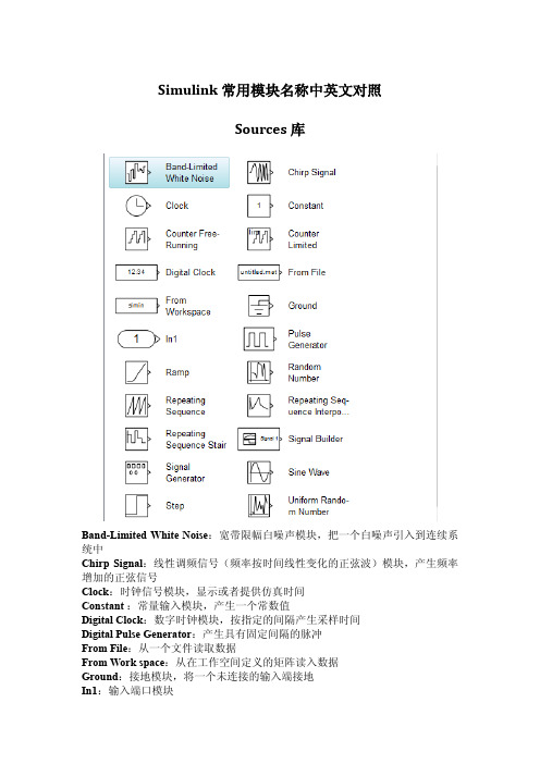
Simulink常用模块名称中英文对照Sources库Band-Limited White Noise:宽带限幅白噪声模块,把一个白噪声引入到连续系统中Chirp Signal:线性调频信号(频率按时间线性变化的正弦波)模块,产生频率增加的正弦信号Clock:时钟信号模块,显示或者提供仿真时间Constant:常量输入模块,产生一个常数值Digital Clock:数字时钟模块,按指定的间隔产生采样时间Digital Pulse Generator:产生具有固定间隔的脉冲From File:从一个文件读取数据From Work space:从在工作空间定义的矩阵读入数据Ground:接地模块,将一个未连接的输入端接地In1:输入端口模块Pulse Generator:脉冲信号发生器模块,产生固定间隔的脉冲Ramp:斜坡信号输入模块,产生一个以常数斜率增加或者减小的信号Random Number:产生正态分布的随机数Repeating Sequence:产生一个可重复的任意信号Signal Generator:产生多种多样的普通信号Signal Builder:自定义信号发生器Sine Wave:产生正弦波信号Step:阶跃信号模块,产生一个单步函数Uniform Random Number:产生均匀分布的随机数Sinks库Display:实时数字显示模块,显示其输入信号的值Floating Scope:浮动示波器模块Out1:输出端口模块Scope:示波器模块,显示在仿真过程产生的信号的波形Stop Simulation:仿真终止模块,当它的输入信号非零时,就结束仿真Terminator:信号终结模块,结束一个未连接的输出端口To File:写数据到文件To Workspace:把数据写进工作空间里定义的矩阵变量XY Graph:用一个MATLAB图形窗口来显示信号的X-Y坐标的图形Continuous库主要用于连续系统的仿真Derivative :微分模块,输出为输入信号的微分。
- 1、下载文档前请自行甄别文档内容的完整性,平台不提供额外的编辑、内容补充、找答案等附加服务。
- 2、"仅部分预览"的文档,不可在线预览部分如存在完整性等问题,可反馈申请退款(可完整预览的文档不适用该条件!)。
- 3、如文档侵犯您的权益,请联系客服反馈,我们会尽快为您处理(人工客服工作时间:9:00-18:30)。
ITS ApplicationsTa-Yin HuDepartment of Transportation and Communication Management Science, National Chen Kung University, No.1, Ta-Hsueh Road, Tainan 701, Taiwan, R.O.C.TEL: 886-6-2757575-53224FAX: 886-6-2753882EMAIL: tyhu@.twTsai-Yun LiaoDepartment of Information ManagementChaoyang University of Technology, Taichung, Taiwan, R.O.C.Li-Wen ChenDepartment of Transportation and Communication Management Science, National Chen Kung University, No.1, Ta-Hsueh Road, Tainan 701, Taiwan, R.O.C.Yung-Kuei Huang, Min-Ling ChiangInstitute of Transportation, Ministry of Transportation and Communications, Taiwan, R.O.C.July 31 2006Revised, Nov 15, 2006Number of words: approximately 8,500 wordsSubmitted for presentation at the Annual Meeting of the Transportation Research Board, Washington, D.C., Jan 2007, and publication in Transportation Research RecordITS ApplicationsTa-Yin Hu1*,Tsai-Yun Liao2, Li-Wen Chen1,Yung-Kuei Huang3 Min-Ling Chiang3 1. Department of Transportation and Communication Management Science, National ChenKung University, No.1, Ta-Hsueh Road, Tainan 701, Taiwan, R.O.C.TEL: 886-6-2757575-53224FAX: 886-6-2753882EMAIL: tyhu@.tw2. Department of Information Management Chaoyang University of Technology, Taichung,Taiwan, R.O.C.3. Institute of Transportation, Ministry of Transportation and Communications, Taiwan,R.O.C.ABSTRACTThis research aims at developing an integrated dynamic simulation-assignment model, DynaTAIWAN under mixed traffic flow conditions, for Advanced Traffic Management Systems as well as Advanced Traveler Information Systems. The model is composed of two layers, namely simulation-layer and real-time control layer. The simulation layer is designed to simulate traffic flow patterns according to assumed tripmaker characteristics and/or under a set of given conditions; the real-time control layer receives real-time vehicle information and forecast short-term traffic flow patterns.In this paper, the simulation layer is discussed in detail and numerical experiments are conducted to illustrate functional capabilities of the proposed model. In the simulation process, each vehicle is moved and tracked individually. Four different vehicle types are explicitly considered in DynaTAIWAN, including car, bus, motorcycle, and truck. Vehicles are moving along the link through macroscopic flow relationships, speeds of each type of vehicle are adjusted. Numerical experiments are conducted in a 50-node test network and a Taichung City Network.KEYWORDS: Simulation-Assignment Model, DynaTAIWAN, Mixed Traffic FlowINTRODUCTIONAs a common and important problem in many urban areas around the world, traffic congestion causes tremendous public concern, Intelligent Transportation Systems (ITS) focus on increasing the efficiency of existing surface transportation systems through the use of advanced computers, electronics, and communication technologies. Although several field experiments have been conducted to demonstrate possible benefits of ITS in Taiwan, a dynamic network model needs to be developed to estimate and forecast possible traffic flow patterns in order to efficiently utilize possible traffic control measures as well as advanced traffic information (Hu et al., 2005). Several dynamic models, including DYNASMART and DynaMIT, have been developed to utilize ITS technologies(FHWA, 2001); however, these models cannot be deployed directly in Taiwan because of mixed traffic flow considerations.This research aims at developing an integrated dynamic simulation-assignment model, DynaTAIWAN (Dynamic Traffic Assignment and Information for Wide Area Networks), for Advanced Traffic Management Systems as well as Advanced Traveler Information Systems. The model is composed of simulation-layer and real-time control layer. The simulation layer is designed to simulate traffic flow patterns according to assumed tripmaker characteristics and/or under a set of given conditions; the real-time control layer receives real-time vehicle information and forecast short-term traffic flow patterns.Four different vehicle types, including car, bus, motorcycle, and truck, are explicitly considered in DynaTAIWAN. In order to reasonably reflect these types of vehicles in a road network, two specific characteristics are essential in the model, namely, route choice behavior and vehicular flow behavior. Route choice behavior governs how drivers select their paths and how they respond to different types of travel information, and vehicular flow behavior determines how vehicles are moved in a network with constraints of traffic control strategies. In DynaTAIWAN, vehicle paths in the network are modeled as the explicit outcome of route assignment decisions at origins or at nodes of the network. Traffic flow is represented using a mesoscopic approach where vehicles are tracked individually in mixed traffic flows, and moved consistently with macroscopic traffic flow relations.Since motorcycle is one of the major modes in developing countries, especially motorcycles are heavily used in Taiwan, its impact on traffic flow is critical to the evaluation of traffic conditions in urban areas in Taiwan. In order to reflect the impact of motorcycles, a two-stage method is developed to model motorcycles along the link and at intersections. Motorcycles are moving along the link through macroscopic flow relationships, and the speed of motorcycles is adjusted according to empirical data. At intersections, motorcycles aremoved according to the sequence of left-turn-waiting section, waiting section, and normal traffic lane. The left-turn-waiting area is designed to store left-turn motorcycles for two-stage-left operations. The motorcycle waiting area is located in front of stop line to store motorcycles during the red phase. The movement of motorcycle is discussed in more detail in Section 3. Numerical experiments are conducted in a 50-node test network and a Taichung City Network to explore the dynamic model under different demand levels and real-time information supply strategies.Next section presents a brief review of related models. The proposed framework and associated modeling issues are described in Section 3. Numerical experiments and results from the Taichung City network, used to illustrate important aspects involved in this procedure, are discussed in Section 4, followed by a brief summary.LITERATURE REVIEWIn this section, two important issues are briefly reviewed and described; including the development of TrEPS and basic characteristics of motorcycle.TrEPSTrEPS represents “traffic estimation and prediction systems for real-time applications” and the main purpose is to develop an on-line model to estimate traffic flow patterns under a variety of strategies(FHWA, 2001). The success of ITS deployment depends on the availability of advanced traffic analysis tools to predict network conditions and to analyze network performance in the planning and operational stages. The FHWA R&D of the U.S. initiated a Dynamic Traffic Assignment (DTA) research project to meet these data needs and to address complex traffic control and management issues in the information-based, dynamic ITS environment. Under the DTA Program, two software systems for online traffic prediction and two for offline traffic operations planning were developed and tested. The two online systems, DynaMIT-R and DYNASMART-X, are being field tested at traffic management centers for online traffic management. The offline systems, DynaMIT-P and DYNASMRAT-P, are being used in several region-wide traffic management projects.The details of these two models are briefly reviewed in the following sections.DYNASMARTDYNASMART-P is a tool to support transportation network planning and operations decisions (Mahmassani, 2001; Mahmassani et al., 2003A, 2003B). Two major conceptsdeployed in DYNASMART-P are network assignment models and traffic simulation models. Network assignment models have been applied primarily in conjunction with demand forecasting procedures for strategic (long-term) planning applications and traffic simulation models have been used primarily for traffic operational studies (Mahmassani et al., 2004A).DYNASMART-X, a real-time simulation-assignment model, interacts continuously with multiple sources of real-time information, such as loop detectors, roadside sensors, and vehicle probes, which it integrates with its own model-based representation of the network traffic condition (Mahmassani et al., 2004B). Major functions include (1) Estimate the state of the existing network; (2) Predict future network states, (3) Determine new routing information around problems, and (4) Support Traffic Management Centers (TMC) in the development of real-time route and scenario information for more efficient system management. Consistency checking and updating is an important function incorporated in DYNASMART-X to ensure consistency of the simulation-assignment model results with actual observations and to update the estimated state of the system accordingly. Another external support function is intended to perform the estimation and prediction of the origin destination (OD) trip desires that form the load onto the traffic network and are, as such, an essential input to the simulation-assignment core (Zhou and Mahmassani, 2006).DynaMITDynaMIT-P is the offline version of the real-time traffic estimation and prediction system and can be used for the evaluation of ITS at the planning level as well as for the evaluation of various short-term planning projects (Balakrishna et al., 2005). It models the day-to-day evolution of traffic, traveler behavior and network performance, in response to special events and situations such as incidents, weather emergencies, sports events etc. DynaMIT-P consists of a supply (network performance) simulator, a demand simulator and algorithms that capture the dynamic and stochastic interactions between demand and supply. The supply simulator captures traffic dynamics in terms of evolution and dissipation of queues, spillbacks etc. The demand simulator estimates OD flows that best match current measurements of them in the network and models traveler behavior in terms of route choice, departure time choice and response to information.DynaMIT-R is a real-time system designed to support the operation of Advanced Traveler Information Systems (ATIS) and Advanced Traffic Management Systems (ATMS) at TMC. DynaMIT considers a variety of models of traveler behavior in a detailed network representation structure (MIT, 2002, 2003A, 2003B). Through an effective integration of historical information databases with real-time inputs from field installations (surveillance data and control logic for traffic signals, ramp meters and toll booths), DynaMIT-R (MIT, 2003C) efficiently achieves (1) estimates of network conditions; (2) predictions of network conditionsin response to various traffic control measures and information dissemination strategies, and (3) generation of traveler information to guide drivers towards optimal decisions.Basic Characteristics of MotorcyclesSince one of the important issues in DynaTAWAN is the modeling of motorcycle. Fundamental characteristics of motorcycles are reviewed. Results from field observation made on motorcycle flows in Taiwan are summarized as follows (Hsu et al., 2003):1.Motorcycles are relatively small in size, giving maneuvering flexibility and the freedom tomove and park. Therefore, motorcycles have the agility and the capability to weave through queues in congested areas.2.Motorcycles do not follow the “First In First Out” rule at intersections, and they alwaysattempt to flock to the front of the traffic stream at intersections.3.In Taiwan, motorcycles are prohibited from driving on freeways and expressways.4.Motorcycles are prohibited to make direct left-turns, and they need to follow two-stageleft-turn movements.5.The motorcycle has higher acceleration rate and shorter reaction time than cars at theintersection upon the starting of green time.6.The cruise speed of motorcycle is lower than the speed of car; therefore, the motorcycleplatoon will be overtaken after a few minute departed from the stop line.7.Motorcycles tend to start early at the beginning of green, thus have negative start-up delay.Many motorcycles stop ahead of the stop line and wait for the green phase on the pedestrian crosswalk.8.The saturation flow of motorcycle depends on their queuing behavior near the stop line.FRAMEWORK OF SIMULATION-ASSIGNMENT MODEL: DynaTAIWAN The main purpose of DynaTAIWAN is to simulate and predict traffic flow patterns for mixed traffic flows in order to develop appropriate ATMS/ATIS strategies for traveler information as well as real-time traffic control. Several important simulation-assignment concepts from both DYNASMART and DynaMIT, such as the interactions among vehicles information and traffic systems, are incorporated and extended to consider mixed traffic flows and en-route switching behavior in the development of DynaTAIWAN. Special efforts have been made in modeling mixed traffic flows and enhancing software development processes, including object-oriented design, analysis, and programming to provide flexibility of the system.The overall framework of DynaTAIWAN is shown in Figure 1. The model is composed of two layers, namely simulation-layer and real-time control layer. These layers are described and discussed in details in the following section.Main objectives of DynaTAIWAN are summarized as follows:1.Estimate flow patterns with consideration of individual tripmaker behavior, both pre-tripand en-route switching decisions.2.Estimate flow patterns with consideration of network supply characteristics, includingnetwork geometric configuration and traffic control strategies.3.Predict flow patterns based on real-time flow data through traffic surveillance andmonitoring systems.Simulation LayerThe simulation layer consists of two major components, demand and supply. The demand component processes tripmaker’s decisions on mode, departure time, and route, thus time-dependent OD trip tables are formed. The supply component includes roadway geometric data, traffic network configuration, and traffic control measures. Thus, vehicles and associated paths are generated and simulated in a realistic traffic environment.Vehicles and associated attributes are generated through the demand data, and are loaded into the network according to the selected departure time and routes. Vehicles are moved individually according to prevailing local speeds, consistently with macroscopic flow relations on links. While the vehicles are moving in the network, travel information is provided through Variable Message Signs (VMS) and in-vehicle information systems.FIGURE1. The Conceptual Framework of DynaTAIWANReal-Time Control LayerIn the real-time layer, it is assumed that real-time data from traffic surveillance systems could be obtained in terms of flow and speed, thus the real-time data can be used to generate short-term OD patterns, resulting in OD trip tables. The OD trip tables are loaded into the simulation layer. The predicted flows are obtained through simulation according to the OD tables, thus provide information for advanced traveler information systems as well as real-time traffic control systems. According to the framework, the simulation layer utilizes the real-time flow data as a guidance to adjust simulation processes, thus could predict the flow pattern based on this modification. Since the real-time flow data could not be possible to cover the whole network, flow data from the simulation layer could be used in the absence of real-time data. Two major tasks in the real-time control layer are dynamic origin-destination(OD) estimation and real-time flow prediction. The Kalman filtering technique is used in OD estimation, and the rolling horizon approach is implemented for real-time flow prediction. The real-time control layer will be reported in another paper.Traffic Flow ModelsVehicular movements in the traffic network are simulated through two processes: link movement and intersection transfer.(1) Link MovementMacroscopic traffic stream models are applied in DynaTAIWAN with explicitly consideration of motorcycles. In order to consider the impact of mixed traffic flows, a passenger car equivalent is used to combine all possible vehicle types, such as bus, truck, and motorcycle. The speed is determined macroscopically and assigned to each vehicle; however, speeds of different vehicle types are adjusted according to empirical data. From several field observations, speeds of different vehicle types are varied along the link, for example, truck is much slower than normal passenger car, and motorcycle tends to slower than passenger car. Thus, observation data is used to adjust speeds according to vehicle types.In the link movement process, the Greenshields model, a linear speed-density relationship, is assumed.)1(k k u u jf =(1)Where u represents speed and k represents density; u f is free-flow speed and k j is jam-density. The model is calibrated based on field data for different types of roads, and vehicle are converted to passenger car units. A dynamic model for motorcycle PCE is proposed and described in the next section. The calibrated motorcycle PCE is used to calculate density in mixed traffic flows, and then speeds are obtained for each vehicle type.(2) Intersection TransferThe transfer process performs the link to link or section to section transfer of vehicles at nodes. The transfer process is controlled by several factors: link saturation flow rate, possible capacity, and possible green time. For interrupted link flow, the transfer process appropriately allocates the right of way according to the prevailing control strategy at intersections. Signal control is explicitly modeled, and phases and green times are calculated according to a time clock in the simulation.It determines the number of vehicles that are traversing each intersection in the network at each simulation time step as well as the number of vehicles entering and exiting the network. The results of the transfer include the number of vehicles that remain in queue and the number added to and subtracted from each link for each simulation time step. A wide range of traffic control measures for both intersections and freeways are reflected in the outflow and inflow capacity constraints of the transfer process. DynaTAIWAN provides the ability to explicitly model an array of control elements for bothsurface streets and freeways in urban areas. The major element for surface streets is signal control, which includes pre-timed control and actuated control. Entrance ramp control and VMS are the major controls for the freeway system. Since VMS provide another means to display real-time information, their application is not limited to freeway systems.Multiple Vehicle ClassesFour physical vehicles are explicitly considered in DynaTAIWAN. Two major issues for these vehicles are addressed: how the vehicle moves in the network, and how the vehicle selects the traveled paths. The motorcycle is described in the next section, and the other three vehicles are discussed as follows:1.Passenger CarThe passenger car is traveled according the velocity, V, obtained from the speed-density relationship, and crosses intersections based on prevailing traffic control measures and available capacity. The path selected is based on pre-trip behavioral rules as well as en-route switching rules.2.TruckThe speed of the truck is approximated as V t = t* V, where t is calibrated based on real data. The truck crosses intersections based on prevailing traffic control measures and available capacity, and each truck represents two passenger car units. The path used for the truck can be either the specified route or the route generated based on behavioral rules.3. BusThe speed of the bus is approximated V. The bus is simulated according to specific routes and stops. In terms of capacity calculation, each bus is represented two passenger car units.Modelling for MotorcycleIn DynaTAIWAN, motorcycles are tracked individually. Along the link, each motorcycle is moved according to speeds obtained from the speed-density function. In order to consider motorcycles in mixed traffic flows, several important characteristics need to be identified: estimation of motorcycle passenger car equivalents (PCE), motorcycle moving speed, and motorcycle movement at intersections.1.Estimation of motorcycle PCEAs discussed in the previous section, the linear speed-density function is used in DynaTAIWAN. In order to appropriately capture impacts of motorcycles on traffic streams, motorcycle PCE needs to be determined from field observations. This research extends the//c i i c iV V PCE A A =(2)Where V c and V i = mean speeds for cars and type i vehicles, respectively, in the traffic stream; and A c and A i = their respective projected rectangular areas (length*width) on the road.()()c ii i i d c c d V V PCE W L L W L L =×+×+(3)i d i ii cdc cL L W V PCE L L W V +×=+×(4)Where V c and V i = mean speeds for cars and type i vehicles, respectively, in the traffic stream; and L c and L i = their respective lengths; W i and W c : their respective widths. L d is the length of detection zone, which is the length of observation area (or the length of detectors). The term of effective length divided by speed is equal to occupancy, denoted as O i , which means the total time period occupied by type i vehicles above detection zone.i i i c cW O PCE W O ×=×(5)Where i W and c W are dynamic width for moving vehicles; i O and c O are occupancy for vehicle type i and passenger car. According to Hsu et al. (2003), the physical length and width of a motorcycle are 1.85 meters and 0.75 meters; the physical length and width of a passenger car are 4.00 meters and 1.55 meters. The length and width of a moving motorcycle (50 kph) are 13.30-16.10 meters and 1.14 meters, respectively. The length and width of a moving car (50 kph) are 16.60-19.40 meters and 2.29 meters, respectively.2.Motorcycle moving speedThe speed of motorcycle is denoted as V m = * V . V denotes the macroscopic speed for link and the adjust factor is about 0.8 ~1.0. The ratio is illustrated in Figure 2, in which shows is varying from 0.8 to 1.0 under different vehicle velocities. In order to simplify the simulation process, only a value of is used, though could be expressed as a function of velocity.FIGURE2.Tendency of Velocity Ratio(Motorcycles/Car)3.Motorcycle movement at intersectionsDue to the large amount of motorcycles, several measures are applied to enhance efficiency and safety of motorcycles. Two major approaches to regulate motorcycle movements are (1) design the queue waiting areas for motorcycles in front of stop lines, (2) enforce the two-stage left-turn movement for motorcycles. Since motorcycles form a flock queue ahead of the traffic lanes during the red phase, the queuing waiting area is designed to store such queue, as shown in Figure 3. The motorcycle follows two-stage left turn to avoid conflict between vehicles and motorcycles. As shown in Figure 3,if a motorcycle wants to make a left turn from direction A to direction B, the motorcyclist needs to go straight, stays in a left-turn waiting area, and goes straight when the light turns green for direction B.Through field data, the saturation flow rates for the left-turn waiting area, the queue waiting area, and the normal traffic are about 6, 5, and 3 motorcycles per second.The usage of motorcycle in Taiwan is primarily in the neighbourhood and for shorter trips, thus most of the motorcyclists are familiar with their travel areas. From several field observations, the motorcyclists tend to use the shortest paths (Hsu et al., 2003), so it is assumed that motorcyclists choose the current best paths for their trips. Also, it is assumed that motorcyclists cannot receive real-time traffic information through in-vehicle information systems, though they can still receive information from VMS en-route.FIGURE3. Movements of Motorcycles at IntersectionsPre-Trip Decision ModelsPre-trip descriptive information provides information about the traffic system to tripmakers before they depart from their origins. The first trip decision is mode choice, and possible modes include bus, car, and motorcycle. If the mode of bus is chosen, the tripmaker then determines the departure schedule for a specific bus route. If the mode of motorcycle is selected, the motorcyclist determines the departure time and follows the current best route selection strategy. If passenger car is chosen, the tripmaker needs to determine both departure times and routes. These decisions are made based on the utility maximization theory, associated Multinomial Logit models are calibrated through survey data.En-Route Decision ModelsAs shown in the overall structure, tripmakers follow two different decision models, pre-trip decision and en-route decision models. Pre-trip decisions include mode, departure time, and route decisions; en-route decisions involve possible switching when tripmaker receive real-time information. The en-route decision models are further described in this section.Real-time descriptive information aims to provide traffic conditions to equipped vehicles while they are in the network. En-route decision models reflect possible route switching behavior under real-time information. While en-route, each driver makes switching decisions based several attributes, such as personal characteristics, network familiarity, and information sensitivity.DynaTAIWAN is able to provide 13 different traffic information strategies, as shown inTable 1, via in-vehicle traffic information system and VMS signs. These information strategies are categorized into three types where each strategy provides drivers with different level of detail of the network condition ahead. Thus, the probability of switching routes under the presence of each strategy is different. The default value will be assigned to each of the parameters.In order to reflect possible information supply strategies, three en-route switching models are developed, namely basic model, market segment model, and advanced model. They are summarized as follows:1. Basic ModelThe basic model reflects that drivers can decide whether to make a switch en-route based on received information.=++++=othersU if C d d d d U i i i ,20,1....................*131312122211 (6)Where i U represents the utility of individual i, *i C , represents the choice; 1: switch to a new route; 2: stay in the original route. i d are dummy variables for each supplied information and i are parameters to be calibrated.2. Market segment ModelBased on the basic model, drivers are classified into 3 groups, namely conservative drivers, aggressive driver, and moderate drivers. The same specification across market segments is assumed and the estimation procedure to the different set of data is applied. 3. Advanced ModelThe advanced model considers decision locations, and possible benefits of switching. The decisions locations are classified to near origin point, in the middle of travel, and near destination point, and the locations are defined according to the percent of remaining trip length. The percent of remaining trip length is classified to 0-20%, 20%-80%, and 80%-100% to represent three decision locations. The benefit of switching is defined as saving of travel time. The equation is described as follows:=+++=othersU if C d d d x U i i i ,20,1*44332211 (7)Where i U represents the utility of individual i, *i C , represents the choice; 1: switch to a new route; 2: stay in the original route. 2d ,3d , and ,4d are dummy variables for different。