Mains frequency harmonics testing
光伏相关的英文术语
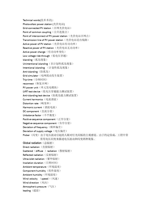
Technical words(技术术语) :Photovoltaic power station (光伏电站)Grid-connected PV station(并网光伏电站)Point of common coupling(公共连接点)Point of interconnect of PV power station(光伏电站并网点)Transmission line of PV power station(光伏电站送出线路)Active power of PV station(光伏电站有功功率)Reactive power of PV station(光伏电站无功功率)Active power change(有功功率变化)Low voltage ride through(低电压穿越)Islanding(孤岛现象)Unintentional islanding(非计划性孤岛现象)Intentional islanding (计划性孤岛现象)Anti-islanding(防孤岛)Grid simulator(电网扰动发生装置)Trip time(分闸时间)reconnect(恢复并网)PV power unit(单元发电模块)LVRT test device(低电压穿越能力测试装置)Anti-islanding test device(防孤岛能力测试装置)Current harmonics(电流谐波)Distortion rate(畸变率)Harmonic current(谐波电流)DC component(直流分量)Unbalance factor(不平衡度)Positive-sequence component(正序分量)Negative-sequence component(负序分量)Deviation of frequency(频率偏差)Deviation of supply voltage(电压偏差)Flicker(闪变)由于电压波动引起的人眼对灯光闪烁的主观感觉。
家用电器的安全要求

家用电器的安全要求EN60 335-1ETL-SEMKOEN60335-1的涵盖内容1. 标准适用范围8. 防触电保护2. 参考标准9. 电机器具的启动3. 定义10. 输入功率和电流4. 通用要求11. 发热试验5. 测试条件12. 空章6. 器具分类13. 工作温度下的电气绝缘7. 铭牌和说明书和泄漏电流EN60335-1的涵盖内容14. 瞬时过压20. 稳定性和机械危险15. 耐潮湿21. 机械强度16. 泄漏电流和电气强度22. 结构17. 变压器和相关电路23. 内部布线的过载保护24. 元件18. 耐久性25. 电源连接与外部软线19. 非正常工作26. 外部导线的接线端子EN60335-1的涵盖内容27. 接地措施28. 螺钉和接头29. 爬电距离, 电气间隙和绝缘穿透距离30. 耐热, 耐燃和耐漏电起痕31. 防锈32. 辐射, 毒性和类似危险标准适用范围什么样的器具是不属于EN60335-1的适用范围?-纯工业用途的器具(EN60204+机械指令)-打算在灰尘, 蒸汽以及可燃易爆环境下使用的器具-黑色家电(音响, 电视机等)------IEC65-IT产品(电脑等)------IEC950-医疗设备------IEC601-电动工具------IEC745标准适用范围-电热毯, 电热垫等------IEC967-电网------IEC1011-试验设备------IEC61010-玩具------EN50088-其他: EN60335-1不考虑儿童及病残者使用的安全问题.标准适用范围什么样的器具是属于EN60335-1范围的, 但需要附加测条件?•-打算在特殊性气候条件下使用的家电•-打算在车辆, 轮船或飞机上使用的家电重点概念的解释1. 正常工作条件: 当器具连接到电源时, 其按正常使用进行工作的状态.2. 特低电压与安全特低电压的区别: 隔离变压器-输入与输出绕组间的绝缘至少是双重绝缘或加强绝缘.3. 用户保养: 制造厂家规定由用户来完成的各种维护保养工作总体要求•器具在设计过程中不仅要考虑正常使用过程中的安全性, 同时也要考虑由于使用时的大意而造成的不安全因素•必须满足包括相关元器件标准在内所有要求•必须通过包括相关元器件标准在内所有必要测试测试条件型式试验的几点重要提示•除非有特殊说明, 测试样品由厂家送样, 一台样机必须通过所有相关的测试项目.•除非有特殊说明, 测试按标准中章节顺序进行.•如果样机结构上很明显能通过某些相关试验, 则这些试验可以省略.•试验一般在20 ±5°C ,无通风的环境中进行•试验通常选择可能发生的最恶劣条件(包括电压, 频率, 安装条件等)进行器具的分类•便携式器具:正常使用时该器具能移动(一般带轮子)或小于18公斤•固定式器具: 非便携式器具•固定安装式器具:正常使用时固定安装于支架上,固定安装于特定的位置上•嵌入式器具:正常使用时该器具安装于厨柜内或墙中预留的壁室内或打算安装在其他器具内•手持式器具:正常使用时握在手中的器具器具的分类•X连接与Y连接:这两种电源软线的连接方式在新标准中的区别开始更注重生产厂家的自我声明以及通过相关试验.•Z 连接: 只有严重损坏才可以更换电源软线.器具分类按防触电类别分类I类器具:基本绝缘+ 保护性接地II类器具:基本绝缘+附加绝缘措施=双重绝缘=加强绝缘(开关)III类器具:安全特低电压(SELV:<42.4Vac(peak)或<42.4Vdc)器具分类按防水等级分类IP等级:IEC 60529: Explanation of IP Numbers for Degrees of Protection一般器具IP 20防滴试验IP X1 雨水溅水试验IP X4 360。
RTTE无线WIFI现场测试记录

6.7
TRANSMITTER UNWANTED EMISSIONS IN THE OUT-OF -BAND DOMAIN (发射机在带外发射多余的排放
量排放设备在传输模式下,频率立即必要带宽外调制过程的结果,但不包括假响应的(本要求适用于所 有类型的跳频设备)................................................................................................................................................ 13 6.7.1 6.7.2 6.8 6.8.1 6.8.2 7 7.1 7.1.1 7.1.2 7.2 7.2.1 7.2.2 8 8.1 8.1.1 8.1.2 8.2 8.2.1 8.2.2 8.3 8.3.1 8.3.2 8.4 8.4.1 8.4.2 8.5 测试要求 .................................................................. 14 测试结果 .................................................................. 14 TRANSMITTER UNWANTED EMISSIONS IN THE SPURIOUS DOMAIN(发射机在杂散域中的不需要的发射) .... 14 测试要求 .................................................................. 14 测试结果 .................................................................. 15
transcat电阻、电容和感受器的atherine测试仪说明书

534 Main Street, Westbury, NY 11590IET LABS, INC. in the G en R ad TraditionTEL: (516) 334-5959 • (800) 899-8438 • FAX: (516) 334-59881USES:•Meters used for impedancemeasurements (inductance, capaci-tance, and resistance) to characterize the performance of a variety of elec-trical components and materials.•Test Resistors, Capacitors, Inductors or any type of passive component •Testing Electronic Components •Calibration abFeatures•0.02% Accuracy for RLC •0.0001 Accuracy for DQ mea-surements.•Programmable test voltagesfrom 5mV to 1.275Vrms •Up to 30 or 50 measurements per second respectively, with high speed option•Wide range of measurement parameters•IEEE-488 Bus and Component Handler Option•Programmable test frequencies from 12Hz to 100kHz for maxi-mum testing versatility.•A full, five-digit LED display for RLC ; our-digit readout for D and QIET cat/1689 7-11-06The GenRad 1689 Precision Digibridge RL C Tester gives you the best performance for your most demanding applications whether they be production test, incoming inspection, component design and evaluation, process monitoring or dielectric measurement. It is a versatile, fullfunction microprocessor-based passive component tester that's available in either bench top (1689) or rack mount-able, high speed (1689M) models.DescriptionThe 1689 is a sophisticated, microprocessor controlled tester that brings new levels of flexibility, simplicity and accuracy to RLC measurement. It is a high performance automated tester with a range of programmable test frequencies and test voltages, as well as automatic limit comparison, automatic parameter selection, remote programmability, automatic bin-ning, and automatic zeroing.The 1689/1689M provides a powerful combination of features designed to maximize productivity in all testing environments.•0.02% Accuracy for RLC measurements.•0.0001 for D and Q measurements.•Programmable test frequencies from 12Hz to 100kHz for maximum testing versatility.•Programmable test voltages from 5mV to 1.275V permits testing at exact manufacturer- specified voltage levels.•Full range keyboard-selectable test speeds: 1689-Variable up to 30 measurements per second with high speed option;1689M-Variable up to 50 measurements per second with high speed option, complements automatic handling equip-ment to maximize throughput.•2 selectable measurement modes: Continuous and Triggered with averaging available in each ensures measurement flexibility.•Optional IEEE-488 Bus and Handler Interface enable remote programming and allow the addition of a component handler to optimize throughput.•Wide choice of measurement parameters allow you to work with familiar units.•A full, five-digit LED display for RLC measurements and a four-digit readout for D and Q testing, simultaneously dis-play both test results for each measurement, automatically.•Guarded Kelvin measurement techniques protect measurement integrity.•Automatic limit comparison and binning ensure fast, mistake-proof sorting of components.534 Main Street, Westbury, NY 11590IET LABS, INC. in the G en R ad TraditionTEL: (516) 334-5959 • (800) 899-8438 • FAX: (516) 334-59882SPECIFICATIONSMeasurement Parameters: C/D, L/Q, R/Q, or C/R (series or parallel)Test Frequencies: Over 500 programmable test frequencies (12Hz to 100kHz) 0.01% Accuracy. Applied Voltage:5mV to 1.275V (programmable in 5mV steps).Measurement Speed:Up to 30 measurements/second with High Speed Option (1689).Up to 50 measurements/second with High Speed Option. (1689M).Measurement Mode: Continuous or Triggered with averaging up to 256 measurements.Display Format:Dual Display featuring 5 full digit LED for RLC and 4 full digit LED for DQR Bin Number, Delta RLC, Delta %, ValueAutomatically positioned decimal points and minus signs where appropriate. Individual LED indicators for parameters, units, and measurement conditions.GO/No GO LightsBias:Internal 2.0VDC External up to 60VDCAutomatic Functions:Auto ranging with manual hold Auto parameter (RLC) with manual selectionBinning: Thirteen pass bins for RLC Two fail bins, RLC and DQRInterfaces:IEEE-488/Handler Interface option, High speed Measurement/IEEE-488/Handler Interface optionRanges:Extended RangesParameter Direct Reading RangeRatio and DQ in PPM R 0.00001Ω to 99999k Ω0.00010μΩ to 9999.9G Ω L 0.00001mH to 99999H 0.00010nH to 9999.9MH C 0.00001pF to 99999μF 0.00010aF to 9999.9F R with C 0.0001Ω to 9999k Ω not extended D with C 0.0001 to 9999 1 to 9999ppm Q with R or L 0.0001 to 9999 1 to 9999 ppmAccuracy:(Primary parameter) Basic RLC ±0.02%.(Secondary parameter)Basic DQ ±0.0001Zeroing:Open and short circuit compensation.General Features:• Charged Capacitor Protection (1 Joule) • DQ in PPM • Keyboard Lock (Store Test Conditions) • Bin Count Summary • Constant Voltage Mode (25Ω source) • Programmed Integration Time• Programmed Delay (1 to 99999ms) • Median Value Mode Test Fixture:4-Terminal Kelvin1689: Built-in1689M: BNC ConnectorsTemperature Effects (Typical):R,L or C ± 5ppm / °C Q or D to ±[2ppm / °C + (3ppm / °C) x frequency in kHz].Dimensions: (w x h x d): 1689: 14.781 x 4.40 x 13.50in (375.4 x 111.8 x 342.9mm) (w x h x d): 1689M: 17.25 x 5.625 x 15.160in (438.15 x 142.87 x 385.2mm)Weight:1689: 10 lbs. (4.5kg) net, 15.1lbs. (6.83kg) shipping.1689M : 14 lbs. (6.41kg) net, 19.1lbs. (8.63kg) shipping.Accessories Supplied: • Axial lead Adapters (1689 only)• 1689-9602 BNC to BNC Extender Cable with Banana/Alligator Clips (1689M only) • Power Cable • Instruction Manual • Calibration Certificate traceable to NIST Enviromental: Operating: 0°C to +50°CStorage: -45°C to +75°CHumidity: <85%Power:• 90 - 250V AC • 50 or 60 Hz• 60W max。
TestingFrequencyMultipliersandDividers

Testing Frequency Multipliers and DividersAuthor: Adrian JonesDate: February 2000IntroductionFrequency multipliers and dividers are key components of modern radio frequency (RF) and microwave systems. They are generally used in signal generation and frequency synthesis applications. These devices can be awkward to characterize due to the frequency conversion between input and output - several pieces of test equipment are usually needed.This paper reviews current techniques for measuring the main parameters of multipliers and dividers, focusing on areas where special considerations are required. In particular, output return loss and phase noise are covered. The application of a microwave system analyzer to multiplier and divider measurements is introduced. Several examples are given to illustrate fast measurements of conversion gain suitable for tuning and manufacturing environments.Common measurement techniquesThe most basic measurement setup consists of a signal generator and spectrum analyzer. This can be used in an elementary fashion to determine the following parameters.Operating window (Input power and frequency)Output powerOutput harmonicsMeasuring these parameters manually over a band of frequencies can be a laborious process and it is common to perform a quasi - swept measurement using a sweeper and the maximum hold facility on the spectrum analyzer. This works well as long as the harmonics of interest do not overlap.Phase noise measurementsThe phase noise of multipliers and dividers is a major concern especially when they are the building blocks of frequency synthesizers. The output phase noise of a multiplier or divider is ideally given by:where L IN and L OUT are single sideband phase noise expressed in decibels with respect to the carrier in a 1Hz bandwidth (dBc/Hz). Dividers improve the phase noise whereas multipliers degrade it. In real devices, the output phase noise is limited by a noise floor. This can be measured by many methods, but most of these require a reference signal significantly better than the device under test.This problem can be overcome with a quadrature mixing method where the devices are measured in pairs (Figure 1). The signal generator phase noise adds to both paths of the measurement, but by adding a variable delay into one of the paths is canceled at the phase detector, leaving just the sum of the additional noise from the two devices. If three devices are available, they can be measured in all combinations to reveal the noise of each individual device. It is particularly important to ensure that only the desired output harmonic reaches the phase detector. The phase detector can be calibrated with a beat note method using another signal generator to drive one of the devices.Input and output return lossComplex RF subsystems are often designed by a team of engineers. To reduce integration problems when the building blocks are connected together, input and output return loss are commonly specified for each block of circuitry.The input match of a divider or multiplier can be measured over the input frequency range using any conventional technique, for example an autotester (return loss bridge) and scalar analyzer. When using a broadband device such as an autotester to measure multipliers and dividers beware of backfire of the output frequency or harmonics causing errors. Ensure that the power at the device input is correct during the measurement, as the input match is a function of input level. When measuring output return loss, it is important that the multiplier or divider is in its normal operating state. A small signal measurement with an autotester or vector network analyzer (VNA) may give false results, as the operating conditions of the non linear parts of the device will be different. Figure 2 shows a possible set-up. The device output is used as excitation for the measurement. A mismatched line is used to reflect power back to the device and the standing wave pattern is used to determine the output match.If the output is loaded with a variable phase short circuit, problems can arise with some devices, especially digital dividers, which could stop running. In this case, a pad can be inserted before the short to provide a controlled mismatch. The forward power on the line is sampled with a directional coupler. By adjusting the length of the mismatched line, the maxima and minima of the standing wave can be observed on a spectrum analyzer tuned to the output frequency. The ratio of maximum to minimum is the voltage standing wave ratio (VSWR) on the line. The return loss of the device under test is given bywhere L pad is the loss of the pad in dB. Errors in this measurement can be analyzed with reference to the flow graph shown in Figure 3.DUT reflection coefficient GsCoupler transmission coefficient TCoupling coefficient CCoupler directivity DPad transmission coefficient T padSliding short reflection angle PThe sliding short is modeled as lossless. The analysis will not be included, but the main result is summarized in the following table. This assumes no pad.As a rule of thumb, the coupler directivity needs to be 10 to 20dB better than the output return loss being measured.Automated measurementsConsiderable time can be saved by automating the preceding measurements with general purpose interface bus (GPIB) compatible instruments and a controller. This technique is very flexible, and a system can be contrived to measure almost any parameter versus frequency, power, time etc.As an example, Figure 4 shows a relatively simple set-up to search for an interesting characteristic in a comb generator. The time varying capacitance in a step recovery diode (SRD) based comb generator makes it easy to inadvertently produce a parametric amplifier. The parametric gain can cause peaks in the noise floor, or even oscillations, generally at half the input frequency, and is often referred to as period doubling instability. In trying to construct a multiplier, a divider has been produced!Considerable difficulties can be experienced in proving the effect has been eliminated as it happens over a narrow range of drive levels and frequencies. A GPIB controlled system can plot regions of period doubling against frequency and drive power - a typical result is shown in Figure 5. This can save substantial development time.Fast swept frequency techniquesRF engineers like to see plots of characteristics against frequency. Even continuous wave (CW) multipliers need to be characterized over frequency to allow for component tolerances and temperature change. For manufacturing, real time tuning and rapid development applications, fast swept measurements are desired.A scalar analyzer can be used to measure divider and multiplier output power, but the high levels of harmonics can cause large errors with broadband detectors. Most spectrum analyzers with tracking generators and vector network analyzers cannot handle frequency conversion devices without external hardware.What is needed is a synchronized source and receiver with the required frequency relationship. Microwave system analyzersThe Microwave System Analyzer (MSA) is new class of instrument which provides the solution by combining a signal generator and spectrum analyzer with an inbuilt controller (Figure 6). In addition, a high accuracy scalar analyzer is included.In most tracking generators, the signal is derived by mixing the spectrum analyzer local oscillator (LO), which only allows frequency offsets to be generated. However if the source and receiver are independently generated, any frequency relationship can be obtained. With a MSA the relationship between the source and receiver frequencies is determined by a scale and offset control. The instrument can be configured into two modes: spectrum analyzer with full band tracking generator (to 24GHz), and scalar analyzer with a tuned receiver input.In spectrum analyzer mode, the frequency range at the receiver is entered and the source frequency is scaled and offset. The instrument acts like a spectrum analyzer with a scaled and offset tracking generator. This mode is convenient for measuring dividers as the scale is simply the divide ratio.In scalar analyzer mode, the source frequencies are entered and the receiver frequency is scaled and offset. This is convenient for frequency multipliers, where the scale is the harmonic number. The instrument acts like a scalar analyzer, except the input is tuned and of high dynamic range. The tuned input can be combined with scalar detectors to measure conversion gain.Example measurements on frequency multipliers and dividers using a MSAAs an example of the spectrum analyzer mode, Figure 7 shows a screen shot of a measurement of the output power of a frequency divider (divide ratio = 8). The MSA scale control has been set to 8 such that the source tracks at 8 times the spectrum analyzer frequency. The frequency scale is annotated in source frequency units. The plot is overlaid with a swept measurement of the output second harmonic level (i.e. scale = 4).As an example of the scalar analyzer mode, Figure 8 shows a comparison of the 2nd and 3rd harmonic measurement of a multiplier. A balanced multiplier is used, which generates a signal rich in odd harmonics and suppresses even harmonics. A dual channel measurement is shown. The measurements are live, and swept alternately. The scale control on each channel has been set equal to the required harmonic number. For example, the 2nd harmonic channel has scale set to 2 such that the spectrum analyzer frequency is always twice the source frequency. The scales are annotated in spectrum analyzer units (output frequency).Measurement accuracy and calibrationThe uncertainties in multiplier and divider conversion measurements must be considered separately at the input and output as the frequencies are different. At the device input, the source level accuracy, cable loss and source match are the dominant factors in uncertainty of incidentinput power. At the device output, receiver level accuracy, load match and cable loss limit the accuracy of the output level measurement.The input cable loss can be compensated for by performing a user power calibration at the end of the cable. The instrument automatically sets the front panel level high enough to compensate for the cable loss. The source match can be improved by increasing the power level and adding 50 ohm attenuators.A through path calibration can be performed over the source or receiver frequency range. The choice depends on the uncertainties at each side of the device under test. The receiver level accuracy is generally worse than the source level accuracy and a calibration over the receiver frequency range is most suitable. This reduces the spectrum analyzer reference level uncertainty to approach that of the source.Characterizing integrated assemblies containing frequency multipliers and dividers Frequency multipliers and dividers are rarely stand alone devices, and are usually part of an integrated system. As an example, Figure 9 shows a comb generator and voltage tuned filter assembly. This circuit takes the VHF signal from a high quality oscillator and selects the 3rd, 4th or 5th harmonic to provide a 1.5 to 3GHz signal.A MSA can be used to perform a swept measurement of the entire signal chain. The speed of the measurement allows the effect of adjustments to the circuit to be seen in “real time”. Figure 10 shows the 3rd harmonic response of the signal chain measured on a MSA - the response can be observed as the voltage tuned filters are adjusted.ConclusionThis paper has reviewed techniques for measuring the key parameters of frequency multipliers and dividers. In particular methods for measuring phase noise and output match have been studied. The flexibility of GPIB controlled techniques was illustrated with the example of a period doubling search on a comb generator.Fast, swept frequency measurements can be made using a microwave system analyzer. It has been shown how this instrument can be used to measure the output level and harmonics of multipliers and dividers. In this application, the instrument is faster and more convenient than using a separate signal generator and spectrum analyzer, which is important in tuning and manufacturing environments. It is also superior to using a scalar analyzer as the tuned receiver can be used to reject unwanted harmonics.。
Megiq 天线模式测试系统说明书

Measure Antenna Patterns in minutesNo anechoic chamber requiredFeatures∙ Measurement of RF device constant carrier or packet stream radiation patterns. ∙ Frequency range 370 / 600 MHz to 4 / 6 GHz.∙ Uncertainty 1dB (anechoic). Repeatability 0.5dB.∙ Measuring distance 0.8 to 3 meter. ∙ 3-axis measurement. Plots per axis and 3D.∙ Simultaneous Horizontal and Vertical polarization measurement.∙ Simultaneous measurement of harmonic radiation.∙Narrow antenna beam width for non-anechoic environments.∙ Minimum step size 2 degrees.∙Integrated PC software suite supports measurement setup, rotation control, graphing, data storage and report generation.∙ Plots of radiated power ERP (dBm), Antenna Gain (dBi), Field Strength(dBuV/m).∙ Calculation of TRP, Minimum, Maximum and Average radiation.∙ Optional Generator output for standalone antenna measurement.∙ Optional Heavy Duty turntable (30kg). ∙ Optional Laser direction pointer.The MegiQ Radiation Measurement System (RMS) is a compact test system that performs 3-axis radiation pattern measurement in non-anechoic spaces.With a frequency range of 370 or 600MHz to 4GHz or 6GHz it is well suited for characterization and measurement of Antenna Radiation Patterns, Antenna Gain, ERP, TRP, Field Strength.Extensive evaluation has shown that – with reasonable setup - the accuracy of the RMS is similar to that of anechoic test labs.Characterize wireless devices of today, like IOT devices, routers, phones, domotica products, electronic gadgets, tablets, laptops, RF-modules etc.The RMS has proven to be a tremendous asset during the development and evaluation of wireless devices. The improved product performance as well as the savings on time consuming range tests and test-lab measurements will pay for the RMS in just a few projects.Radiation Measurement System370/600 MHz to 4/6 GHzMeasurement SystemEUTTurn Table∙ Height 70cm and 130cm. ∙ Stepper motor drive. ∙ 30 seconds per rotation. ∙ Smooth acceleration. ∙ Table size 28 x 28cm. ∙Max EUT weight: 7.5kg.∙ Heavy Duty table: 100 x 50cm, 30kg.Measurement∙ Antenna height 100cm to 170cm. ∙ Dual Polarization Antenna. ∙ Dual channel measuring receiver. ∙ Generator output (option). ∙ Rotation controller unit. ∙ Power supply.∙USB connection for computer control.The RMS rotates an object on the turntable and measures the radiation. With a rotation around the X, Y and Z axis the software plots the patterns and calculates statistics including Total Radiated Power (TRP). Each measuring point can contain a sweep of multiple frequencies, so that multiple radiation patterns can be measured in one rotation sequence.With the Generator option the RMS can also perform an antenna sweep and show the antenna gain over frequency.The RMS comes with an object fixture for small devices that allows easy positioning of the EUT in orthogonal positions on the object table. A labeling system helps the user to keep track of the axes.The RMS system works well in a moderate space. A 4 x 4 x 3 meter room works well above 800MHz. For smaller spaces or lower frequencies a few strategic absorbers may be required.A report on accuracy evaluations of the RMS is available on request.SoftwareThe RMS software controls the measurement system and allows easy setup and performing the measurements, organizing the data and create reports. It will guide the user through the 3 rotation axis steps.For EUT with a constant carrier or packet stream mode the RMS is used in a passive mode to rotate the EUT and record the field strength. For constant carriers, the receiver can measure multiple frequencies for each measurement point so that harmonic patterns (up to 4 or 6 GHz) can be measured simultaneously. The minimum step size is 2 degrees.For EUT without a transmitter (prototype or standalone antenna) the Generator output can be used to feed a test signal to the EUT. In this mode the RMS can measure rotation patterns (at up to 30 frequencies simulations) or perform a frequency sweep of the antenna gain. The S- parameters of the feed coax can be imported to compensate for the loss and impedance of the cable.In idle mode the RMS monitors the signal and shows the polarization in real time. It can also transmit a carrier with a calibrated power on the horizontal or vertical antenna.The results can be presented in Antenna Gain (dBi), Radiated Power EiRP (dBm) or Field Strength (dBuV/m). The software calculates statistics such as Min/Max level, Average, Total Radiated Power (TRP), Antenna Efficiency (dBi) and Directivity (dB).The rotation table can be controlled manually and a rotation offset aides in the rotation of largeobjects.MeasurementsAntenna rotation and linear patternsHarmonicsMax gain and efficiency over frequencyBeam Max Gain, Front to Back ratio, Beam Width over frequencyRMS SpecificationsRMS0440 / RMS0460unitRMS0640 / RMS0660FrequencyMHz Frequency range 370 – 4000 / 370 - 6000600 – 4000 / 600 – 6000Frequency accuracy 2 ppm Frequency resolution 5 kHz MeasurementAntenna Height 100 - 164 cm Measuring distance 80 - 300 cm Antenna polarization Dual polarization antennasReceiver Dual channel receiverPhase coherency Phase coherent between H and VpolarizationBase Receiver bandwidth 20 kHz Minimum Field Strength 75 – 90 / 75 - 100 dBuV/m Measurement accuracy (anechoic) +/- 1.0 dB Repeatability 0.5 dB Turn TableHeight 70 / 130 cm Platform 28 x 28 cm Max load 7.5 kg Stepper motor rotation speed 30 sec / Rot ConnectionsPower 95 - 240 VAC PC Interface USB 2.0Generator (option)Port Connector SMA femaleFrequency range 370 - 4000600 – 4000MHz Output level -30 - +5 dBm Heavy Duty Turn Table (option)Height 110 cm Platform 100 x 50 cm Max load 30 kg Laser Pointer (option)Laser class Class 2 / < 1mWPC SoftwareOperating System Windows XP – Windows 10PC minimum requirements Pentium I3 – 2 GHzPC recommended requirements Pentium I5 – 2.4 GHz Measurement CharacteristicsPhysical Quantities Field StrengthEffective Isotropic Radiated PowerAntenna Isotropic GainAntenna efficiency dBuV/m dBm dBi dB, %Amplitude Statistics Min, Max, AverageTotal Radiated PowerTotal Isotropic Gain Beam Statistics Beam Center3dB Beam Width10dB Beam WidthFront / Back ratio Graphs Gain, Phase over FrequencyStatistics over FrequencyPolar Rotation PatternsLinear Rotation Patterns。
音频性能量测参数的定义

物理意义 : 音质的纯净程度,harmonics 强度愈少,表示主讯号愈干净. (THD 值愈负,表示愈 佳)
2
2-1.一个良好的单一频率玄波讯号,其在频谱上展开,主讯号强度远超过谐波,因此其 THD 值极 佳.
2-2.一个饱和(截波)的玄波讯号,可视为由许多倍频玄波合成,因此在频谱上展开,将显示出其 成份,依 THD 的数学定义计算,其 THD 将随谐波成份增加而变差.
在计算 THD 的过程中,考虑 DSP 有限点数的计算可能影响 THD 的计算准确度,因此一般(含 Audio Precision)改采 THD+N (THD+Noise)的表示方式,一如图所示先将主讯号以 notch filter 移除,计算 FFT 转换后所有讯号的 RMS 值 值.
V22 + V32 + ... + Vn2 ,再加入主讯号计算其 THD+N
5-2.What is ripple? Why it occurs? 依 Nyquist theory, 在不造成 alias 现象的前提下,48KHz sample rate 最高可 sample 24KHz 的 audio signal,因此滤除高频的 noise 变的相当种要,CODEC 中以 digital filter 来滤除 24KHz 以上的 audio signal, 理想上该 filter 的频率响应应为一完美的频谱,然而在欲达成该频率响应的 代价是 digital filter 的 tape 数(乘加器)的数量将非常大. 以 CODEC clock rate 为 12.288MHz 计算,所允许的 tape 数最多为 12.288MHz/48KHz = 256, 其所形成 digital filter 的频率响应实际 情形将出现 ripple 的现象:
EMI经典资料

EN55022測試法規非故意輻射、故意輻射非故意輻射(Unintentional):產品產生不想要的電磁波輻射,造成干擾¾ITE (Information Technology Equipment):電腦,LCD Monitor ,DVD 、電視、投影機、¾DOC (Declaration of Conformity):自我認證方式¾証實驗室測試的報告不用被審核,但在外銷國該地會被抽驗故意輻射(Intentional):使用無線電波來通信¾RF 產品:WLAN、手機¾管制比較嚴格¾歐規: 採行DOC方式¾FCC : 採行FCC ID 方式¾認証實驗室測試的報告必須通過TCB 審核,取得FCC ID後才可販售 FCC 只測試EMI :¾RE (輻射干擾):Radiation Emission (30MHz ~ 1GHz)量測頻率範圍(30MHz ~ 1GHz)¾CE (電源線干擾) : Conducted Emission量測頻率範圍(150KHz ~ 30MHz)EMI測試:EN 55022EMI 測試:測試待測物(EUT)產生輻射干擾的強度量測EUT產生的輻射干擾(Radiated Emission) :RE¾測試方法:依據EN 55022¾10米量測(Open Area Site)¾量測EUT產生的電磁波輻射(30MHz ~1GHz)量測EUT產生的傳導輻射干擾(Conducted Emission) :CE¾測試方法:依據EN 55022¾量測電磁波雜訊出現在EUT的DC 和AC電源端(150K ~30MHz)¾量測Telecommunication ports 端出現輻射干擾值(150K ~30MHz):量測EUT產生的諧波電流干擾值:Power Harmonic¾測試方法:依據EN 61000-3-2¾量測EUT在交流電源端的諧波電流,避免對電力公司造成影響量測EUT的輸出電壓變動和閃爍(Voltage fluctuation and flicker) :Flicker ¾測試方法:依據EN 61000-3-3¾量測EUT的AC電源端的電壓變動和閃爍值10 米電波暗室10m chamber 價格大約NT 4,000萬場地符合標準?Absorber 不可能對30MHz ~ 1GHz 的電磁波全部吸收缺點:反射比OATS 強優點:可以避免空中廣播FM (88MHz~108MHz) ,手機(900MHz)干擾量測天線:Bi-Log侍測物(EUT)歐規採用10 米量測FCC 採用3米或10 米量測都可以150KHz to 30MHz Open Area Test Site (10 m)侍測物傳導干擾量測OATS (Open Area Test Site)FRP Doom量測天線:Bi-Log OATS 價格便宜優點:反射比10m chamber 小缺點:受空中廣播FM (88MHz~108MHz) ,手機(900MHz)干擾必須在深山,遠離市區Measuring Distance 轉換New limit (dBuV/m)=published limit(dBuV/m)+20log[d/new distance (m)] d=the distance identified within the test standard.例如10m轉換3m limit37 + 20log(10m/3m)37+20*0.52=~47CISPR 22 A1:2005-07 版本中RE (Radiated Emission) 的量測已要求1GHz以上,最高到6GHz,而且1GHz以上是採用3米量測。
- 1、下载文档前请自行甄别文档内容的完整性,平台不提供额外的编辑、内容补充、找答案等附加服务。
- 2、"仅部分预览"的文档,不可在线预览部分如存在完整性等问题,可反馈申请退款(可完整预览的文档不适用该条件!)。
- 3、如文档侵犯您的权益,请联系客服反馈,我们会尽快为您处理(人工客服工作时间:9:00-18:30)。
S l i d e 1Tuesday, 01 February 2000Harmonic Current EmissionsPhilip W. Carter a CE mark europe ltdA simple low frequency test or a complex nightmare? An overview of the current status of the EMC StandardPart 3: Limits – Section 2:Limits for harmonic current emissions(Equipment input current £16 A per phase)S l i d e 2Tuesday, 01 February 2000Introduction•IEC/EN 61000-3-2 introduced in 1995–Main issues with Class D products•Number of Ambiguities–Confusion over Class D wave -shape»Envelope shape »Each Half Period–Confusion over basis for Class D limits»Complex interpretation »Rated Load Condition »Measured LoadThe International Standard was published in 1995 and has since developed into the most controversial of all the EMC standards.In the main the problems are mostlyrestricted to Class D products. A number of areas are poorly defined within the document and have lead to a variety of interpretations. S l i d e 3Tuesday, 01 February 2000Introduction• A very ambiguous standard–Several apparently valid interpretations•Most test systems now allow various interpretations to be set up as defaults–No Guidance available for which to choose –Need for consistent approachThe muddle was clear from the first attempts to accredit laboratories to this standard where it became evident that there were several very differentimplementations and many shortcomings to conform to the requirements.Although many of the test systems have evolved significantly since they were introduced and can now demonstrate various options, they can still havesignificant differences in approach, method and results when testing transitory harmonics.S l i d e 4conditions given in the relevant clause of annex C.Some of the ambiguities will become clear if we take a look at the current standard. As you can see there are four Classes of equipment. The last Class, ‘D’ has a definition that requires the wave shape to meet the definition of figure 1 the active input power to be measured and for it to be less than 600Watts. S l i d e 5Overview of standardEquipment shall be deemed to be Class D if, under the test conditions given in annex C, the input current wave shape of referred to its is within the envelope as given in figure 1 duration of each half-period ; this implies that wave forms having small peaks outside the envelope are considered to fall within the Envelope. The centre line, M, coincides with the peak value of the input current.When we read each statement within the standard we must decide a. What it means and b. whether we comply with it. From an Assessor viewpoint the onus is me to ask these questions from the point of Black and White. This comes from the point of view that if it is not wrong it is right.So from this what does each half cycle mean? S l i d e 6Overview of standard6.2 Harmonic current measurementWhen limits for harmonic currents are given as a function of the fundamental current or active input power, input power shall be measured under the same conditions The limits are applicable to steady-state harmonic currents measured according to annexes A, B and C.Here we have another statement that is possibly confusing. “The currents and input power shall be measured under the same condition.” Some exponents of the complex solution argue this can only mean a simultaneous measurement of current and voltage throughout each 16 cycle (320mS) window and calculate an active input power from this. Then apply this active input power to calculate a limit. This limit is then applied to the Harmonic currents measured in the same window.Where does it say that?S l i d e 7Tuesday, 01 February 2000Overview of standard–6.2.2 Transitory state•For transitory harmonic currents, measured according to annexes A, B and C, the following applies:–a) harmonic currents lasting for not more than 10 s when a piece of equipment is brought into operation or is taken out of operation, manually or automatically, are disregarded;This is another area where most original implementations were unable to comply with the standard requirement to ignore up to but no more than 10 seconds.S l i d e 8Seems innocuous enough but the proper implementation of this filter has not been demonstrated for all analyser solutions.S l i d e 9Overview of standard7 Harmonic current limitsThe following limits apply, with the provision that the limits f high-power equipment (>1 kW) for professional use are kept under 7.1 Limits for Class A equipmentFor Class A equipment, the harmonics of the input current shall not absolute values given in table 1.7.2 Limits for Class B equipmentFor Class B equipment, the harmonics of the input current shall not maximum permissible 7.3 Limits for Class C equipmentQ.What is the difference between ‘absolute values’ and ‘maximum permissible values’? A.It seems they mean the same thing but it keeps us guessing!S l i d e 10Here come the next two questions:What does ‘rated load condition’ mean?When is the implementation date of this standard?(Given that it becomes mandatory in January 2001 does that mean 2005?) S l i d e 11Tuesday, 01 February 2000Class D LimitsThe table giving the limits applicable to Class D equipment shows how the limits are proportional to the power and given in terms mAmps of Harmonic current per Watt.Note that Class D equipments do not have any even Harmonic limits. S l i d e 12Tuesday, 01 February 2000Overview of standard• B.1 General•Any type of wave analyser may be used, for example,frequency -domain instrumentation using selective amplifier, heterodyne, multiple passive filters, spectrum analyser tuned to the frequency to be measured and time-domain instrumentation using digital filters or Discrete -Fourier-Transform (DFT). The instrument may be of either the indicating or the recording type. The following requirements ensure the equivalence offrequency -domain and time-domain instruments in a practical sense.The Standard clearly and unambiguously maintains that the analysers may befrequency or time domain. Specifically it may be a spectrum analyser tuned to the harmonic frequency of interest. And also defined that it may be an indicating or recording type.S l i d e 13Another significant point coming from Annex B is that there is no preferredmeasurement method and more importantly no reference measurement method.S l i d e 14Annex CThe test conditions for the measurement of harmonic currents associated with some types of equipment are given in theFor equipment not mentioned there, users’ operation controls or automatic programmes shall be set to produce the maximum harmonic components under normal operating conditions for each successive harmonic component in turn.The equipment is tested as presented by the manufacturer.Preliminary operation of motor drives by the manufacturer may be needed before the tests are undertaken to ensure that resultscorrespond with normal use.Annex C gives the definitions for the measurement configuration for various types of equipment.This particular clause however makes a requirement that if the equipment is not included in the Annex then a series of measurements need to be performed to ascertain the maximum harmonic currents for each harmonic in turn all (40 of them). This is an incredibly complex requirement and could take a test laboratory many days of investigation to identify the true maximum harmonic currents.When we wanted to change this clause we were told by a previous convenor that it was the only way to get the manufacturers to the negotiating table.No wonder compromise is not coming easy!S l i d e 15Tuesday, 01 February 2000Annex C10 ITE–C.10 Test conditions for information technology equipment (ITE)•ITE is tested with the equipment configured to its rated current . In this case, the equipment, if necessary, may be configured with its power supplies loaded with additional load (resistive) board s to simulate rated current conditions.•For ITE systems designed for use with a manufacturer-supplied power distribution system, e.g. transformers, UPS, power conditioner, etc., compliance with the limits of this standard shall be met at the input to the power distribution system.For ITE equipment the annex specifies that the equipment be tested configured to its rated current.For some equipment this would mean the manufacturers would need to makehundreds of different cards to simulate the variety of configurations possible.S l i d e 16Tuesday, 01 February 2000EMCTLA Experiment•Attempt to quantify problem–Do the various equipments used by the test laboratories give different measured results?–Do the various equipments used by the test laboratories give different limits?–Do the test laboratories make different interpretations of the standard?Clearly there are a number of issues to concern the testing laboratory as well as the manufacturer. It was decided within the EMC Test Laboratories Association in the UK to conduct a laboratory inter-comparison exercise to see how results would compare between the installed base of test solutions.The three basic questions were addressed in the comparison by limiting the set-upprocedure supplied to the equipment under test only.S l i d e 17Three basic equipment under test conditions were evaluated the firstcompared the steady state results from the different laboratories.The results shown indicate an extremely good correlation between the different test analysers. S l i d e 18EMCTLA ExperimentTest 1 Limits791Harmonic NumberWhen we review the limits chosen by the laboratories to apply for this test we do see three limit values that do not fall into line with the expected pattern.Generally however the correlation crossed the boundaries of test systems and the three odd results were not strictly associated with a particular test system type.S l i d e 19This is a test where the programmable load is modulated with a pulse waveform to give two distinct states or levels.This represents a fluctuating load with levels of 2 to 4 Amps, 0.25 Hz, 10% duty cycle. The transient increase in current to 4 amps occurs once every 4 seconds and lasts for 400mSecondsAgain we have a fairly good correlation of results. S l i d e 20EMCTLA ExperimentTest 2 Limits57910Harmonic NumberHere we can see the limits chosen by the test systems for these results to be compared against.There are two fairly distinct levels chosen for limits, approximately 300mA and approximately 500mA.Some of the histogram bars are blank where the results fell between the 100% and 150% amplitude levels for more than 10% of the measurement time.The laboratories concerned could not provide these limits. They may not be available due to the need to summarise such a vast amount of data.S l i d e 21EMCTLA ExperimentTest 3 Results7910Harmonic NumberThe results for the third test a moresignificant fluctuation fluctuating load of 2 to 7.5 Amps, 0.25 Hz, 20% duty cycle this time not only a higher transient current is simulated but also an 800mS transient time.Still the measured results are surprisingly consistent.S l i d e 22Here we can really see a differencebetween the various approaches taken by the test system suppliers. The limits that have been chosen are between 400mA and 850mA for the 3rd Harmonic current level.Some of the histogram bars are blank again where the results fell between the 100% and 150% amplitude levels for more than 10% of the measurement time. S l i d e 23Tuesday, 01 February 2000EMCTLA Experiment•Preliminary Conclusions–Do the various equipments used by the test laboratories give different measured results?•Very Good Correlation for Steady State, and still reasonable for transitory harmonic tests!–Do the various equipments used by the test laboratories give different limits?•Significantly over 100% variation, many limits not known by laboratory!–Do the test laboratories make different interpretations of the standard?•Tend to rely on the defaults of the software!The results of the initial analysis indicate that there are indeed problems in testing to the current test standard. Although we have a surprisingly good correlation between measurement solutions for the actual harmonic currents we have significant differences in the calculated limits to apply to the results achieved.These results have been achieved with little intervention in the test system setting from those that represent the default values. A great reliance has been made on the test system manufacturers having correctly interpreted the standard.Understandably in this case we see the ambiguity showing through.S l i d e 24Tuesday, 01 February 2000EMCTLA Experiment•Areas of controversy not explored by experiment.–Wave-shape interpretations•Each half cycle •Half cycle areaThe current experiment has not evaluated differences due to the other areas of controversy. It is only speculation how much these would have an effect, but it must be considered likely that from the defined envelopes in some test solution providers that some equipment would not consistently be allocated into class D.Some of the approaches considered clearly implement the complex analysis of limits. Frequency domain solutions have not yet been analysed, however it is clear that such techniques would not agree on limit values established by the complex methods.S l i d e 25Tuesday, 01 February 2000Wave-shape InterpretationsThere are two specific issues associated with the analysis of the wave-shape and comparing the shape measured with the envelope.If the wave shape goes out of the envelope for any half cycle during the measurement period, does that put the equipment into Class A?If we have any DC offset on the waveform and the current waveform falls below the baseline shown in the envelope for more than 5% does this then fall into Class A? Intended or not this is the only black and white interpretation of this standard.S l i d e 26 Tuesday, 01 February 2000Complex Vs Simple•Complex approach–Different limit for each 320mS (proposed 200mS) time window equating to up to 469 limits per harmonic during the test (proposed 750). Giving 18,760 separate test limits for each test (proposed 30,000).–For fluctuating harmonics double the above numbers or add another 1876 limits (proposed 3000) to the final figure when 10% values are calculated.•Simple approach–Use Rated Power if available–Measure maximum current and calculate 1 limit for each HarmonicWhat justification can there be for making the measurement of power line Harmonic currents the most complicated analysis in EMC history? 18, 760 separate limits to compare our results to.It also begs the question of how many of these 18760 different limits would be the same when measured at another laboratory. What would it mean to a manufacturer to be told that he fails in the 353rd time window by 7mAmps, when the time window before was a higher value but an even higher limit so it passed. How would he go about investigating that?Surely even common sense requires a complete rethink and getting back to some simple limits.S l i d e 27Tuesday, 01 February 2000Frequency Domain Measurement•Would it be possible to measure the fluctuating limits in each 320mS window with a Spectrum Analyser–Could we establish 18,760 limits?–Could we see the 10% time period allowed higher fluctuations and establish further 18,760 *150% limits•Could they be equivalent methods–with the complex interpretation?I do not propose to even try to suggest a method of using a frequency domain instrument such as a spectrum analyser to try and emulate the complex approach.The standard clearly mandates that the methods are equivalent.Have the committees inadvertently or otherwise mislead some test equipment manufacturers into jumping the gun and implement solutions from a future standard never yet agreed to?S l i d e 28Tuesday, 01 February 2000What’s Happening Now?•Document prepared by Working Group 6 using simple limit approach for CENELEC proposed to IEC.•IEC established several new Task forces to address revision.•Latest Proposal now being written as committee Draft.•May be voted on and implemented in time for Jan 1st2001.At last a breakthrough!While I have no comment on the need for the limits or their applicability to the range of products falling within the scope of the standard, if the new proposal goes through we will at least be in abetter position to make realistic tests. S l i d e 29Tuesday, 01 February 2000Main Features of New Draft•Single Limit system for Class C and D–Average value of all measured Harmonic Currents –Maximum Measured value to establish Limits•Removal of Annex C1•Class D Products Defined–600 Watt Maximum / 75 Watt minimum–PC’s, Monitors, TV’s, Video’s, Multimedia*, Printers*,Fax Machines*, *Not Professional equipmentThe new draft offers a significant leap forward in terms of clarification. Not only has it standardised on the single limit approach but many of the other areas of controversy have been eliminated. Most significant is the list of products which fall into Class D. S l i d e 30Tuesday, 01 February 2000Main Features of New Draft•Less Ambiguous–Conflicting Statements removed –Single method using time domain–Annex B extracted from new 61000-4-7•specified power–Manufacturer defines power when near boundaries•i.e.Products near 75 Watt or 600 Watt limits •Allows for production variationsIt is intended that the Manufacturer will have certain discretion in the specifying of power levels etc to avoid confusion when products are close to specification boundary conditions.S l i d e 31Tuesday, 01 February 2000Main Features of New Draft•Better flow graphThe New propsal include a simplified flow graph, completely losing the need to perform the ambiguous waveform shape test.S l i d e 32Tuesday, 01 February 2000Current Equipment•Generally software and Firmware upgrades–Most manufacturers claim equipment is upgradeable•Compatibility of results–For steady state equipments differences are small –Small advantage to products with varying load–Test using measured power for limits where possible andselect single limits if possibleFrom discussion that I have had with several test equipment manufacturers, it is likely that most systems will be modifiable to meet the new requirements.S l i d e 33Tuesday, 01 February 2000Timescales•Committees voting over next two months •Aim to introduce before 1/1/2001•???It’s ironic, if a proper compromise had been found five years ago the standard would be in and working by now! Clearly an indication that the more simple the solution the more likely it is to work.S l i d e 34Tuesday, 01 February 2000Other considerations•Equipment Calibration–Analysers can be calibrated at NPL –Sources still a problem•Need for full Calibration CapabilityCalibration remains an issue for theHarmonic current measuring equipment. In the UK our National Standards Laboratory NPL has developed a calibration service for the analyser part of the equipment. Traceable Calibrations for the sources remain a problem. S l i d e 35Tuesday, 01 February 2000Flicker Standard EN 61000-3-3•Does your product have a peak inrush > 30 Amps?•If yes watch out for some implementations–Already hijacked with introduction of D max limit–Attempts to imply moment of switch on is part of test –Make sure you know how the test is being carried out•Just like with Harmonics testing, due to the poor wording in the standards, accreditation bodies could not ensure a single approach is taken.As an addendum to the Harmonics debacle of the last 5 years the sister standard EN 61000-3-3 is also the subject of some confusion.Biased committee representation was not limited to Harmonics and the same people were responsible for attempting to hijack the Flicker standard and turning it into a Peak Inrush test as well as the existing Flicker requirements.Already different equipment manufacturers have different implementations, some including the moment of equipment switch on in the test period.The effect of this is to cause any product with an inrush current of over about 29 amps to fail the Dmax requirement.Does this affect you?。