水下机器人的机械手
水下机器人-机械手系统自适应抗扰控制方法

水下机器人-机械手系统自适应抗扰控制方法李冀永;万磊;黄海;张国成;秦洪德【摘要】针对开架式水下机器人在其作业过程中易受到脐带缆、机械手和海流等扰动影响的问题,为减小改扰动对艇体姿态的影响,文中对开架式水下机器人设计了一种基于模型的自适应抗扰控制方法,并分别对脐带缆和机械手引起的扰动进行了建模分析,具体建立了一种以全局运动学控制环和扰动力补偿项为主的自适应抗扰控制.在SY-Ⅱ开架式水下机器人平台上进行了S面控制和自适应抗扰控制的对比实验.结果表明,脐带缆和机械手的扰动力会对水下机器人的姿态产生较大影响,通过对扰动力的实时估算和补偿,在定深定向、轨迹跟踪实验中,基于模型的抗扰控制方法表现出更高的控制精度,在姿态保持实验中,与S面控制方法相比,自适应抗扰控制展现了较好的鲁棒性,系统轨迹更平稳,具有更强的稳定性.%Open frame underwater vehicles tend to be affected by the disturbances caused by manipulator,tether,waves and other factors.In order to reduce the influence of disturbances,in this article a model-based adaptive anti-disturbance control (AADC) method for open frame underwater vehicles was proposed.The models of disturbances caused by manipulator and tether was analyzed,and an AADC method in details based on global dynamic control loop and disturbances compensation terms was established.Experiments carried out on SY-Ⅱ open flame underwater vehicle to compare the AADC with the S surface control show that manipulator and tether indeed caused certain disturbances on the vehicle.The AADC method shows higher control accuracy through the estimation and compensation of disturbance in deep keeping,orientationkeeping and path following experiments.When it comes to the position keeping experiments while the manipulator is at work,AADC method is robust against disturbance,hence generating smoother trajectory in vehicle motion and showing better stability performance than S surface control.【期刊名称】《天津大学学报》【年(卷),期】2018(051)004【总页数】9页(P413-421)【关键词】水下机器人;机械手;脐带缆;抗扰控制【作者】李冀永;万磊;黄海;张国成;秦洪德【作者单位】哈尔滨工程大学水下机器人技术重点实验室,哈尔滨150001;哈尔滨工程大学水下机器人技术重点实验室,哈尔滨150001;哈尔滨工程大学水下机器人技术重点实验室,哈尔滨150001;哈尔滨工程大学水下机器人技术重点实验室,哈尔滨150001;哈尔滨工程大学水下机器人技术重点实验室,哈尔滨150001【正文语种】中文【中图分类】TP242.6开架式水下机器人在海底观测、海洋工程的管道检测与资源开发、海底作业等方面广泛应用.它们可以通过水面或母船的遥控在极端危险的大深度领域完成潜水员无法胜任的工作[1].然而由于在实际环境中,机器人面临海流等外界环境的干扰,脐带缆[2]和机械手[3]也会同时给载体带来扰动,所以实现开架式水下机器人的长时间精确作业还需要研究精确的控制方法.开架式水下机器人在其作业过程中受到多方面扰动的综合影响,其中以脐带缆的拖曳力和机械手的干扰力为主.由脐带缆拖曳力造成的扰动影响使操作人员难以对水下机器人进行精确的位置控制;而机械手给水下机器人的悬停定位作业时带来的扰动力(矩),更会对其作业姿态造成较大影响.因此必须深入分析水下机器人的扰动力的特性,对作业过程中机械手、脐带缆产生的扰动力进行补偿.文献[4-5]分别设计了滑膜控制器和状态反馈控制器对水下机器人进行运动控制,但都没有建立水下机器人所受的扰动力模型.在水下机器人-机械手系统方面,文献[6]针对水下机器人-机械手系统设计了一种自适应控制器,但其动力学模型参数存在较大的不确定性,因此较难应用.文献[7-8]分别基于能量的方法和拉格朗日方程对水下机器人-机械手系统建立了动力学模型,但并没有给出二者耦合运动时机械手给水下机器人的扰动力矩.文献[9-10]系统地分析了机器人-机械手系统的运动学模型,并给出了系统作业过程中浮心和重心变化派生的恢复力(矩),然而并未在模型中给出艇体和机械手相互耦合作用的表达式.脐带缆也会对开架式水下机器人产生较大的扰动,文献[11]建立了脐带缆带来的干扰力模型.文献[12]基于有限元技术,通过PD控制器对脐带缆造成的干扰力进行补偿.文献[13]同时考虑了海流和脐带缆对水下机器人的影响.但上述三者在分析时涉及了较复杂的数值计算,因此在引入机器人外部扰动力分析后,控制器的设计将更加复杂.本文通过对开架式水下机器人机械手和脐带缆的扰动力分别进行建模和分析,建立一种基于模型的自适应抗扰控制方法,通过该控制方法对水下机器人进行全局控制,并对影响机器人姿态的扰动力进行实时观测和补偿,从而减小机器人作业过程中的扰动,使其更精确地进行作业任务.本节提出了一种基于卡尔曼滤波器的间接自适应控制器,先基于卡尔曼滤波器估计模型中的未知变量,再将估计后的状态变量应用于控制器中.一个典型的开架式水下机器人结构如图1所示.包括前视声呐、水下摄像机等探测设备;磁罗经、深度计等运动感知传感器;水下机械手等作业设备.控制指令、传感器信息和动力电通过脐带缆在水面和水下之间传输.开架式水下机器人的动力学模型为式中:为开架式水下机器人系统惯量矩阵,,为质量相关的惯量和质量矩阵,为附加质量矩阵;为机器人在艇体坐标系的位置状态;为哥氏力(包括由附加质量引起的);为受到的流体黏性力(包括流体惯性力和黏性力);代表航行和作业过程的恢复力矩;为控制输出力;为机器人所受到的干扰力.根据动力学模型,所设计的开架式水下机器人的控制律为式中:上角标代表观测量;代表机器人所受到的外界环境干扰;为S面运动学控制环,当偏差较大时控制指令比较疏松,当偏差较小时控制指令比较细,在一定程度上也体现了模糊控制的思想[14];在控制器中,代表期望加速度;和的维数相对应;和分别代表比例系数和微分系数;和分别代表位置偏差和偏差变化率.通过机器人配置的多普勒测速仪、深度计、磁罗经等传感器,可获取机器人的实时首向角、纵倾角、横倾角、速度、深度等信息,机器人的实时运动转台可通过扩展卡尔曼滤波器(EKF)获得式中:为滤波器结算后的UVMS各自由度的位置;为观测矩阵;为传感器获取的状态量;为观测噪声矩阵.结合式(2)和式(3)可得到基于模型的间接自适应抗扰控制器为结合式(1)和式(4),形成闭环系统为由于惯量矩阵可逆,所以有其中,加速度误差为,且有考虑到S面运动学控制环可展开为式中为第j项伯努利数.故如果忽略高阶项,式(7)可以线性化为这样定义Lyapunov函数为式中:为正常数,,为的最小特征值,这样对非零向量有,即.这就意味着为正定对称阵.另一方面,设为正对称阵,常数,所以有Lyapunov函数关于时间的导数为由于,,,将式(7)代入上式得由于矩阵和为正定对称阵,所以如果通过控制器使得则为全局负定的.根据Lyapunov稳定性定理,在平衡点全局渐近稳定,即所以控制器为全局一致渐近稳定的.开架式水下机器人在水下作业,主要受到来自脐带缆、机械手和海流等的扰动力.下文分别分析脐带缆和机械手扰动力的估计方法,以实现运动控制中的补偿.在海流扰动条件下,脐带缆对开架式水下机器人有重要的非线性干扰.脐带缆在流体中的动力学模型可以描述为式中:为未拉伸的拉格朗日坐标系;为施加在上的张力;为单位长度脐带缆的质量;为惯量加速度;为单位长度的脐带缆在水中受到重力,,为海水的密度,g为重力加速度,为脐带缆的密度,为脐带缆的横截面积;为单位长度下的流体作用力.根据图2所示的受力状况,可以将脐带缆的扰动分为水面、水下和与机器人的连接点几个部分.脐带缆在水面的端点速度为零,点所受的拖曳力为式中、和分别为x、y、z方向的拖曳力. 这样,对于空气中脐带缆第i个微元的受力方程为式中:为脐带缆在水平方向的拉伸长度;为脐带缆在垂直方向上的拉伸长度;为空气中第i段脐带缆微元的重量,;脐带缆局部坐标系下和是第i段脐带缆微元的两端受力;代表风对第i段脐带缆微元的作用力;代表拖曳系数;是风相对于脐带缆的速度[15],,为水平面10,m高处风速,代表图2中距离水平面的高度,为脐带缆在水面的参考点距水面距离.类似的脐带缆在水中有式中:;和是在坐标系下第j个脐带缆微元两端的张紧力;是作用在第j个脐带缆微元的海流扰动力;是脐带缆相对于水的速度.对于在脐带缆末端与机器人的相连接位置有式中:H为从上的脐带缆局部坐标系到艇体拖曳点坐标系下的转换矩阵;代表机器人在点受到的合力;、和是开架式水下机器人在点受到来自脐带缆的水平和竖直方向的拉力.所以在脐带缆的局部坐标系下,脐带缆的张紧力可以计算为式中和分别代表脐带缆微元在空气中和水中的加速度.因此脐带缆对开架式水下机器人的扰动可以表示为式中代表拖曳点相对于机器人质心的坐标.如图3所示,在作业过程中机械手和开架式水下机器人之间的相互作用主要体现在两个方面:一是重心和浮心变化给机器人平台造成的恢复力矩;二是机器人和机械手之间的耦合作用力.机械手的运动给开架式水下机器人所造成的恢复力矩为式中:和为艇体坐标系下机械手第i个广义连杆的重力和浮力,艇体坐标系下载体所受到的重力和浮力分别为、,其中,,而开架式水下机器人相对于绝对坐标系的变换矩阵为机械手的第i+1个广义连杆相对于第i个广义连杆的变换矩阵为式中:为第i个关节的zi轴和第i+1个关节的zi+1轴之间的夹角;为第i个关节绕zi轴旋转角;和分别为开架式水下机器人的重心和浮心;和分别为机械手第i 个广义连杆的重心和浮心.另一方面,水下作业时机械手和机器人遵循动量矩守恒.所以根据Newton-Euler 方程,机械手的第i个广义连杆所受的惯性力和力矩分别为式中:为机械手第i个广义连杆的质量;为机械手第i个广义连杆的质心相对于第i个关节坐标系的惯量阵;为机械手第i个广义连杆的质心相对于第i个关节坐标系的线速度;为第个关节相对于第i个关节坐标系的角速度.因此机械手第个广义连杆所受到的力和力矩为式中:和分别为机械手第i个广义连杆所受到的流体作用力;和分别为第i个广义连杆在第i-1关节处所受到的约束反力(力矩);代表旋转关节的矢量,,为第i个广义连杆两端关节的距离,为第i个连杆的长度;,为第i个广义连杆几何中心的运动矢量.关节递推过程按文献[16],即因此机械手对开架式水下机器人的干扰主要为恢复力矩和耦合作用力的总和,即为了验证和分析所设计的控制器,在哈尔滨工程大学水下机器人技术重点实验室的综合水池(50,m×30,m×10,m)分别进行了轨迹控制和机械手作业的协调控制实验.用S面控制方法[14](式(8))和本文提出的自适应抗扰方法(式(4))进行了对比得式中为控制器输出最大值.实验平台为SY-Ⅱ开架式水下机器人平台(如图4所示,平台的水动力系数如表1所示).该机器人长1.3,m、宽0.8,m、高0.6,m,配有2个主推螺旋桨、2个侧推螺旋桨、2个垂推螺旋桨和1个具备两俯仰关节机械手,机械手相关参数如表2所示.脐带缆和机器人的固定点在机器人的艉部中点,所以脐带缆给机器人造成的横倾力矩为0,脐带缆相关参数如表3所示.它通过水面控制台向水下机器人嵌入式计算机发送控制指令,实现它的运动控制.文中首先进行了同时定深定向控制,在水面同时进行机器人的艏向控制和深度控制,目标艏向120°,深度3,m,如图5所示.机器人在水面下潜,同时到达期望深度和艏向姿态.和S面控制相比,所设计的控制器基于模型和机器人的艏向、俯仰、和横倾等姿态实时估计了机器人所受到的脐带缆等扰动力,并通过自适应抗扰控制实时补偿,从而降低了控制误差,提高了收敛速度和控制精度.在路径跟踪过程中,机器人通过多普勒和磁罗经推算机器人的实时位置,分别跟踪了空间Z型曲线和空间螺旋线,虽然S面控制也可以实现跟踪,但所设计的控制器根据机器人的三维姿态、航行速度实时估计机器人所受到的脐带缆等扰动力,通过自适应抗扰控制实时补偿,并在控制过程中不断比较期望路径和实际路径的误差,实现了更加精确的路径跟踪.本文研究了控制器在水下机器人机械手作业过程中的姿态控制能力,在作业过程中机器人的姿态的稳定直接影响到机械手末端的作业精度和效率,所以作业过程中的姿态能力将较大提高机器人的悬停抓取和作业的精度和效率.图6(a)中,机械手的肘关节在水中进行俯仰运动,图6(b)中,机械手的肩关节和肘关节在水中同时进行俯仰运动,在机械手运动过程中,机械手的俯仰运动主要给机器人的俯仰姿态造成了影响.可从图6(c)和(d)中观察到肘部运动时机械手对机器人的扰动力和扰动力矩;图6(e)和(f)表示了肩-肘联合运动对机械手的干扰力和干扰力矩.由此可见,机械手的运动,尤其是肩-肘联合运动会对机器人产生较大的干扰影响.在协调运动控制中,机器人通过前后两个垂推进行姿态控制,抑制机械手影响的机器人俯仰运动,保持机器人的姿态平稳.在姿态控制过程中,所设计的控制器根据磁罗经得到的机器人俯仰、横倾和艏向等姿态角,机械手的各关节反馈角,实时估计机器人所受到的机械手扰动力,并进行补偿.和S面控制相比,基于模型的自适应控制器因为能够估计到机械手的扰动力,所以机器人的姿态平稳,控制精度高.脐带缆的拖曳力和机械手的扰动力会对开架式水下机器人的作业造成较大扰动影响,为使水下机器人以更稳定的姿态进行精确作业,本文针对开架式水下机器人设计了一种基于模型的自适应抗扰控制方法,该控制方法主要由全局运动学控制环和扰动力补偿项组成.文中通过系统动力学模型和Newton-Eulerian反向递推方法分别得到了脐带缆和机械手对水下机器人的扰动力模型,模型中包含机器人受到的海流扰动力、脐带缆的拖曳力及其产生的扰动力矩、机械手带来的耦合力(矩)和恢复力(矩).通过上述对两种扰动力的建模,建立了含有具体扰动力补偿项的自适应抗扰控制方法.进一步通过SY-Ⅱ开架式水下机器人进行实验验证,实验表明,相比于S面控制,基于模型的自适应抗扰控制方法通过对扰动的实时补偿,在定深定向、路径跟踪的实验中,降低了控制误差,提高了收敛速度和控制精度.而在涉及机械手运动的水下机器人作业实验中,通过对机械手扰动的实时估计和补偿,基于模型的自适应抗扰控制方法在机器人的姿态控制上较S面控制方法表现出更大的优越性.【相关文献】[1]徐玉如,肖坤. 智能海洋机器人技术进展[J]. 自动化学报,2007,33(5):518-521. Xu Yuru,Xiao Kun. Technology development of autonomous ocean vehicle[J]. Acta Automatica Sinica,2007,33(5):518-521(in Chinese).[2]吴家鸣,崔寅,邓威,等. 控制动作下带缆遥控水下机器人的水动力特性[J]. 华南理工大学学报:自然科学版,2012,40(4):150-157.Wu Jiaming,Cui Yin,Deng Wei,et al. Hydrodynamic characteristics of tethered underwater robot under control manipulations[J]. Journal of South China University of Technology:Natural Science Edition,2012,40(4):150-157(in Chinese).[3]陈巍,魏延辉,曾建辉,等. 水下机器人-机械手系统控制方法综述[J]. 重庆理工大学学报:自然科学版,2015,29(8):116-123.Chen Wei,Wei Yanhui,Zeng Jianhui,et al. Review of underwater vehicle manipulator system control method [J]. Journal of Chongqing University of Technology:Natural Science,2015,29(8):116-123(in Chinese).[4] Bian X,Qu Y,Yan Z,et al. Nonlinear feedback control for trajectory tracking of an unmanned underwater vehicle[C]//IEEE International Conference on Information and Automation(ICIA 2010). Harbin,China,2010:1387-1392.[5] Bagheri A,Karimi T,Amanifard N. Tracking performance control of a cable communicated underwater vehicle using adaptive neural network controllers[J]. Applied Soft Computing Journal,2010,10(3):908-918.[6] Antonelli G,Caccavale F,Chiaverini S. Adaptive tracking control of underwater vehicle-manipulator systems based on the virtual decomposition approach[J]. IEEE Transactions on Robotics and Automation,2004,20(3):594-602.[7]郭莹. 水下自主作业系统协调控制技术研究[D]. 武汉:华中科技大学船舶与海洋工程学院,2008.Guo Ying. Coordinated Control Technology of Underwater Vehicle-Manipulator System[D].Wuhan:School of Naval Architecture and Ocean Engineering,Huazhong University of Science and Technology,2008(in Chinese).[8]彭生全. 水下机器人-机械手系统运动规划与控制技术研究[D]. 哈尔滨:哈尔滨工程大学机械与电气工程学院,2012.Peng Shengquan. Research on the Motion Planning and Control for Underwater Vehicle-Manipulator System [D]. Harbin:College of Mechanical and Electrical Engineering,Harbin Engineering University,2012(in Chinese).[9] Ismail Z H,Dunnigan M W. Redundancy resolution for underwater vehicle-manipulator systems with congruent gravity and buoyancy loading optimization[C]//Pro-ceedings of the 2009 IEEE International Conference on Robotics and Biomimetics. Guilin,China,2009:1393-1399.[10] Han Jonghui,Chung Wan Kyun. Active use of restoring moments for motion control of an underwater vehicle-manipulator system[J]. IEEE Journal of Oceanic Engineering,2014,39(1):100-109.[11] James C K,Yang Q J,Jonathan C H. Nonlinear dynamic model-based state estimators for underwater navigation of remotely operated vehicles[J]. IEEE Transactions on Control Systems Technology,2014,22(5):1845-1854.[12] Sairam P,Bradley B. Dynamics modeling and control of a variable length remotely operated vehicle tether[J]. Oceans,2005,2(2005):1255-1262.[13] Mario A J,Jorge L B. Guidance of underwater vehicles with cable tug perturbations under fixed and adaptive control systems[J]. IEEE Journal of Oceanic Engineering,2008,33(4):579-598.[14]唐旭东,庞永杰,李晔. 基于S 模型的水下机器人改进人工免疫控制器[J]. 大连海事大学学报,2008,34(1):49-53.Tang Xudong,Pang Yongjie,Li Ye. S model-based improved artificial immune controller for autonomous underwater vehicle[J]. Journal of Dalian Maritime University,2008,34(1):49-53(in Chinese).[15] Montano A,Restelli M,Sacco R. Numerical simulation of tethered buoy dynamics using mixed finite elements computer methods[J]. Applied Mechanics and Engineering,2007,196(41/42/43/44):4117-4129.[16] Tsai Lung-wen. Robot Analysis[M]. New York:Wiley,1999.。
毕设翻译,水下机械手的理论和设计问题(译文)
国际控制会议,仪器仪表和机电工程(CIM'07)Johor Bahru, Johor, Malaysia,5月28-29,2007水下机器人的理论和设计问题Irfan Abd Rahman, Surina Mat Suboh, Mohd Rizal Arshad马来西亚理科大学albiruni81@,sue_keegurlz@,rizal@m.my摘要在本文中,我们将讨论水下机械手设计的理论和实现面临的问题。
这是由以前的研究人员工作中提取的集体的信息和方法。
本文介绍了一些建模参数,这是通常包含在水下机器人的外观设计,增加质量,增加corriolis,阻力和浮力。
模拟所有这些参数使用MATLAB通过修改一些代码运行,是由彼得·柯克通过他的机器人工具箱完成的。
对一个土地基础的设计和水下机械手的设计进行了比较, 由于作为水下机械手执行其工作添加参数,指出增加转矩要求做出类似的运动关节链接。
在本文中,我们使用了彪马560配置,这作为我们的手动工具的机器人工具箱内部生成的。
本文给出了用下一个方向的项目和改进。
1.介绍探索海洋已经成为一个新兴的研究领域,由于许多资源位于深海之下。
深海勘探给人类带来了不同的挑战,因为我们不能够承受苛刻的条件。
因此为了避免在深海中的人为干预,机器人的研究已进入深海。
当前热门的研究领域主要集中在AUV(自主水下载具)的开发和部署。
水下机器人能够操纵自己进入深海。
这将消除人类的水下勘探被暴露在危险环境中。
AUV的一些应用程序,包括检查。
水下机器人配备了照相机来执行其检查周围覆盖面积的职责。
水下AUV预计将在未来取代人类从海洋探险的危险起到至关重要的作用。
机械手的设计和应用是另一个领域的深入研究,将使机器人复制人类的手臂和手的功能。
各个实用的应用程序已被研究如配售及拧紧装配零件。
机械手的设计通常由它能够执行或“操纵”本身的度数决定,或换句话说是DOF(自由度)。
自由度是指机械手拥有的基本关节的数量。
机械手
1 机械手概述用于再现人手的的功能的技术装置称为机械手。
机械手是模仿着人手的部分动作,按给定程序、轨迹和要求实现自动抓取、搬运或操作的自动机械装置。
在工业生产中应用的机械手被称为工业机械手。
工业机械手是近代自动控制领域中出现的一项新技术,并已成为现代机械制造生产系统中的一个重要组成部分,这种新技术发展很快,逐渐成为一门新兴的学科——机械手工程。
机械手涉及到力学、机械学、电器液压技术、自动控制技术、传感器技术和计算机技术等科学领域,是一门跨学科综合技术。
工业机械手是近几十年发展起来的一种高科技自动生产设备。
工业机械手也是工业机器人的一个重要分支。
他的特点是可以通过编程来完成各种预期的作业,在构造和性能上兼有人和机器各自的优点,尤其体现在人的智能和适应性。
机械手作业的准确性和环境中完成作业的能力,在国民经济领域有着广泛的发展空间。
机械手的发展是由于它的积极作用正日益为人们所认识:其一、它能部分的代替人工操作;其二、它能按照生产工艺的要求,遵循一定的程序、时间和位置来完成工件的传送和装卸;其三、它能操作必要的机具进行焊接和装配,从而大大的改善了工人的劳动条件,显著的提高了劳动生产率,加快实现工业生产机械化和自动化的步伐。
因而,受到很多国家的重视,投入大量的人力物力来研究和应用。
尤其是在高温、高压、粉尘、噪音以及带有放射性和污染的场合,应用的更为广泛。
在我国近几年也有较快的发展,并且取得一定的效果,受到机械工业的。
机械手是一种能自动控制并可从新编程以变动的多功能机器,他有多个自由度,可以搬运物体以完成在不同环境中的工作。
机械手的结构形式开始比较简单,专用性较强。
随着工业技术的发展,制成了能够独立的按程序控制实现重复操作,适用范围比较广的“程序控制通用机械手”,简称通用机械手。
由于通用机械手能很快的改变工作程序,适应性较强,所以它在不断变换生产品种的中小批量生产中获得广泛的引用[7]。
2 机械手的发展史现代工业机械手起源于20世纪50年代初,是基于示教再现和主从控制方式、能适应产品种类变更,具有多自由度动作功能的柔性自动化。
水下机器人技术及其应用实例分析
水下机器人技术及其应用实例分析近年来,水下机器人技术逐渐走进人们的视线,这种现代化的技术不仅在工业生产中大展拳脚,同时也在深海探测、环境监测、海洋拓展等方面发挥着越来越重要的作用。
水下机器人技术是指一种能够在水下环境下工作及自主完成各种任务的电子机器设备,包括无人潜水器、机器人、无人机船等。
本文将从水下机器人的组成结构、应用场景以及现实应用实例等方面展开分析。
一、水下机器人的组成结构水下机器人的整体结构主要由外壳、摄像头、照明器、液晶显示器、电机、电器、控制系统等组成。
其中,外壳是用于保护电路和电子设备的核心部分,主要承担起防水和抗压的作用;摄像头和照明灯是用于拍摄和照明的,能够快速获取水下信息,实时回传数据;液晶显示器和控制面板是用于显示电路和控制的操作面板,能够直观地了解水下机器人的状态。
除此之外,还需要安装相应的控制系统和软件,以实现对水下机器人的操作与控制。
二、水下机器人的应用场景水下机器人能够完成各种任务,如水下探测、海洋资源勘探、水下搜救、水下拆弹等。
在海洋勘探方面,水下机器人可以快速检测那些人类无法到达的深海油气资源;搜救中,水下机器人能够快速定位受困人员的具体位置,提高搜救的成功率;水下拆弹方面,还可以用于探测隐蔽下降在水下的敌对水雷等。
三、水下机器人的现实应用实例1、搜救:在2014年的马来西亚MH370飞机失事事件中,无人潜水器就承担起了寻找飞机残骸的任务,这使得整体搜索过程更为高效且安全。
2、海洋勘探:挪威斯塔托石油公司2019年在北海的施鲁斯堡油气田对深海钻探进行了尝试,任务使用了该公司最新的海洋科技。
二维和三维空间信息的处理等设施可远程控制一个自主的水下机械手,该机械手可以执行对岸设施无法完成的操作。
3、科学研究:2018年,中国科学家在距离西班牙近万公里的海底,通过控制水下机器人轻松完成了跨越太平洋向美洲拓展塔斯曼海种床的目标。
这为随后的海底地壳实验提供了奠基性的工具。
水下机器人机械手臂的设计与控制
水下机器人机械手臂的设计与控制随着科技的不断发展和应用,水下机器人成为了深海探索和海洋资源开发中不可或缺的工具。
而机械手臂作为水下机器人的“手”也显得尤为重要。
本篇文章将重点探讨水下机器人机械手臂的设计与控制。
一、机械手臂的设计1. 基本结构水下机器人机械手臂的基本结构一般包括机械臂主体、关节、末端执行器和控制系统。
机械臂主体是机械手臂的主支架,关节连接机械臂主体和末端执行器,控制系统是整个机器人的大脑,也是机械手臂的运作中枢。
2. 关节类型机械手臂的关节类型包括旋转关节、线性关节和旋转线性关节。
旋转关节由一个旋转轴固定在机械臂主体上,可以在水平或垂直平面内旋转;线性关节是指沿着直线方向移动的关节,用于伸展机械手臂;旋转线性关节则是既可以沿着直线方向移动又可以旋转的关节。
3. 末端执行器机械手臂的末端执行器一般有钳子、操作器、抓取器等多种类型。
根据机器人的应用场景和需求选择合适的末端执行器非常重要。
4. 简化设计为了避免机械手臂的结构复杂,降低制造成本和运行维护的难度,有时会采用简化设计方案。
例如,机械手臂的关节数目、类型和布局可以进行优化,通过降低复杂度来提高整体的性能和稳定性。
二、机械手臂的控制1. 控制算法机械手臂的控制算法是保证机器人正常运行的核心部分。
常见的控制算法包括PID控制、自适应控制和神经网络控制等。
PID控制是一种经典的控制算法,可以实现位置控制、速度控制和力控制;自适应控制能够根据不同工况自动调整控制参数;神经网络控制则可以模拟人脑的思维方式,具有自学习和自适应的能力。
2. 传感器机械手臂的传感器一般包括编码器、压力传感器、视觉传感器、声呐传感器等。
编码器可以实时感知机械手臂的位置和速度;压力传感器可以测量机器人与周围环境之间的接触力,帮助机器人避免碰撞;视觉传感器可以拍摄周围场景,实现机器人的视觉导航;声呐传感器可以探测水下环境的距离和深度。
3. 增量式控制增量式控制是一种非常常见的机械手臂控制策略。
水下机器人机械手臂的设计与控制
水下机器人机械手臂的设计与控制在水下环境中,机械手臂需要具备良好的自由度和灵活性,以完成各种复杂的任务,例如探测海底资源、进行海底建设和维护等。
因此,机械手臂的设计需要兼顾结构刚性和运动自由度之间的平衡。
在机构结构设计方面,水下机器人机械手臂通常采用串联多关节链结构,以增加其自由度,并且可以实现较大范围的工作空间。
每个关节通常由电机、减速器和传感器构成,其中电机提供驱动力,减速器用于减小电机输出的转速,并增加扭矩,传感器用于测量关节的角度和位置信息。
通过控制各个关节的运动,整个机械手臂可以实现复杂的运动轨迹和姿态。
在选择执行器方面,由于水下环境中存在高压、低温和腐蚀等特点,传统的执行器如液压和气动执行器往往难以满足要求。
因此,电动执行器常常被用于水下机器人机械手臂中。
电动执行器具有结构简单、体积小、响应速度快、易于控制和维护等优点,并且适应水下环境的要求。
目前,常用的电动执行器包括直流电机、步进电机和伺服电机等。
在控制策略方面,水下机器人机械手臂的控制可以分为位置控制和力/力矩控制两种方式。
在位置控制中,通过控制各个关节的位置,使机械手臂达到期望的姿态。
常用的控制算法有PID控制、自适应控制和模糊控制等。
在力/力矩控制中,机械手臂通过感知外部环境的力或力矩信息,并对其进行反馈控制,以实现对物体的抓取、操纵和移动等任务。
力/力矩控制常用的算法有力/力矩反馈控制和神经网络控制等。
此外,水下机器人机械手臂还需要考虑以下几个方面的特点。
首先,由于水下环境的高压和腐蚀性,机械手臂需要采用防水和防腐蚀材料进行封装和保护。
其次,由于水下环境的视觉信息受限,机械手臂通常需要结合其他传感器,如压力传感器和声纳传感器等,以提供更多的环境信息。
最后,机械手臂的控制系统需要具备很高的稳定性和可靠性,以应对复杂的水下工作环境。
综上所述,水下机器人机械手臂的设计和控制涉及机构结构设计、执行器选择和控制策略等多个方面。
通过合理的设计和控制,机械手臂能够在水下环境中具备较高的操作能力和任务执行效果,进一步推动水下机器人技术的发展。
水下大臂展机械手动力学建模与仿真分析
Vol. 45 No. 5May. 2021第45卷第5期2021年5月液压与$动Chinese Hydraulics & Pneumatics doi : 10.11832/j. issn. 1000-4858.2021.05.003水下大臂展机械手动力学建模与仿真分析刘 涛1!2'3'4 ,张奇峰^3,张运修1!2'3'4 ,孙英哲1!2'3'4 ,范云龙心(1.中国科学院沈阳自动化研究所机器人学国家重点实验室,辽宁沈阳110016;2.中国科学院机器人与智能制造创新研究院,辽宁沈阳110169;3.辽宁省水下机器人重点实验室,辽宁沈阳110169;4.中国科学院大学,北京100049)摘 要:面向水下环境大范围精细作业需求,对水下大臂展机械手系统进行动力学建模和关节驱动力矩求解分析。
首先,基于D-H 理论对水下大臂展机械手进行正、逆运动学分析,求解各连杆速度与加速度; 然后,构建水下大臂展机械手的动力学模型,使用莫里森公式和D-H 理论完善动力学模型中的水动力项,采 用拉格朗日法求解整机的净浮力、惯性力、离心力、科氏力与末端负载力项,得出各关节所需驱动力矩和关节角、环境水流速度以及末端负载之间的函数关系;最后,针对具体作业场景,得出环境水流速度、目标负载转 运下机械手各关节所需驱动力矩,为水下大臂展机械手设计提供理论支撑。
关键词:水下机械手;大臂展;水动力;动力学;运动学中图分类号:TH137;TH113 文献标志码:B 文章编号:1000-4858 (2021 )05-0025-08Dynamic Modeling and Simulation Analysis of UndeDvaterManipulator w 让h Larye ArmsLIU TVO 1,2,3,4 , ZHANG Qi-feng 1,2,3, ZHANG Yun-xio 1,2,3,4 , SUN Ying-zha 1,2,3,4 , FAN Yun-long 1,2,3( 1 .SiaieKeyLaboaaioayoeRoboiocs , ShenyangInsioiuieoeAuiomaioon , ChoneseAcademyoeScoences , Shenyang , Loaonong 110016;2. Insioiuies eoaRoboiocsand Inie e ogeniManueaciuaong , ChoneseAcademyoeScoences , Shenyang , Loaonong 110169;3.KeyLaboaaioayoeMaaoneRoboiocs , Shenyang , Loaonong 110169;4. University of Chinese Academy of Sciences , Beijing 100049)Abstract : Aiming at tha requirement of larya-scaia accurate obsecation and operation of undeoVar environment , dynamocmodeeongand ioonidaoeongmomenioeundeawaieamanopueaioawoih eaageaamsaaeca a oed oui.Foasiey ,based on iheD-H iheoay , iheeoawaad and oneeasekonemaiocsoeundeawaieamanopueaioawoih eaageaamsos anaeyaed.Meanwhoeeiheeeeocoiyand acceeeaaioon oeeach eonk aod aaesoeeed.Then , ihedynamocmodeeoeiheundeawaieamanopueaioawoih eaageaamsosconsiaucied.Amongihem , ihehydaodynamocieamson ihedynamocmodee aaepeaeecied usongMo a oson eoamueaand D-H iheoay.And iheLagaangemeihod osused iosoeeeiheneibuoyancy ,oneaioaeoace , ceniaoeugaeeoace , Coaooeoseoaceand ieamonaeeoad ieam oeihewhoeemanopueaioa.In ihosway , iheeuncioonaeaeeaioonshop beiween ihedaoeongioaqueand iooniangee , amboeniwaieaeeoweeeocoiyand ieamonaeeoad oe each iooniosobiaoned.Fona e y , accoadongioihespecoeocopeaaioon scene , consodeaongiheeeeocoiyoeeneoaonmeniae eeowand iaageieoad , ihedaoeongioaqueeoaeach ioonioeihemanopueaioaaaeobiaoned , whoch paoeodesiheoaeiocae suppoaieoaihedesogn oeiheundeawaieamanopueaioawoih eaageaams.Key words : undeDvatar maniyulatcr, larya amis , hydrodynamic , dynamics , kinematics收稿日期:2020-11-09修回日期:2020-12-16基金项目:国家重点研发计划(2016YFC0300401,2017YFC0306402);中国科学院战略性先导科技专项! XDA22040102)作者简介:刘涛(1995—),男,山西晋中人,硕士研究生,主要从事水下机械手方面的研究。
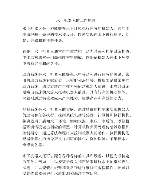
水下机器人的工作原理
水下机器人的工作原理
水下机器人是一种能够在水下环境执行任务的机器人。
它的工作原理基于先进的技术和设计,以便实现在水下进行探测、勘察、维修和救援等任务。
首先,水下机器人通常由主体结构、动力系统和控制系统构成。
主体结构通常采用高强度材料制成,以保证机器人在水下环境中的稳定性和耐久性。
动力系统是水下机器人能够在水中移动和进行任务的关键,常用的动力系统有螺旋桨、水喷射和涡轮等。
螺旋桨是最常见的动力系统,通过旋转产生推力来驱动机器人前进。
水喷射系统则喷出高速的水流来推动机器人前进,具有较高的机动性能。
涡轮则通过涡轮效应来产生推力,提供高速和高效的动力。
控制系统是水下机器人的大脑,通过精确的控制来实现机器人的运动和任务执行。
控制系统包括传感器、计算机和执行机构。
传感器用于感知水下环境,例如水温、水压、水质等,以便根据环境情况做出相应的调整。
计算机则负责处理传感器数据和控制指令,通过算法和程序来控制机器人的动作。
执行机构则根据计算机的指令来执行相应的操作,例如探测、采集样本、维修设备等。
水下机器人还可以配备各种各样的工具和设备,以便完成特定的任务。
例如,可以安装摄像头和声纳来进行水下拍摄和声呐探测;可以安装机械臂和夹爪来进行维修和救援操作;还可以安装传感器来进行水质监测和海洋生物研究。
总之,水下机器人凭借先进的技术和设计,能够在水下环境中执行各种任务。
通过主体结构、动力系统和控制系统的协同工作,它可以在水下环境中保持稳定、敏捷地移动,并通过传感器感知、计算机控制和执行机构操作来完成各种任务。
- 1、下载文档前请自行甄别文档内容的完整性,平台不提供额外的编辑、内容补充、找答案等附加服务。
- 2、"仅部分预览"的文档,不可在线预览部分如存在完整性等问题,可反馈申请退款(可完整预览的文档不适用该条件!)。
- 3、如文档侵犯您的权益,请联系客服反馈,我们会尽快为您处理(人工客服工作时间:9:00-18:30)。
ScienceDirectIFAC-PapersOnLine 48-2 (2015) 294–299Available online at2405-8963 © 2015, IFAC (International Federation of Automatic Control) Hosting by Elsevier Ltd. All rights reserved.Peer review under responsibility of International Federation of Automatic Control.10.1016/j.ifacol.2015.06.048© 2015, IFAC (International Federation of Automatic Control) Hosting by Elsevier Ltd. All rights reserved.Keywords: Underwater application, AUV, Manipulation, Robot hand, Hand design.1. INTRODUCTIONn the world of scientific research, there is a particular attention to innovative robotic manipulators for next-generation robots. These devices should be able to compete with the human hand in terms of functionality. This field of robotics has recently known a notable development, thanks tothe growing interest towards its multiple applications,including medical implants or automated devices capable ofreplacing human intervention in activities such asmanipulation and exploration in hostile environments.There are two types of robotic hands: humanoid and industrial. The former are based on the anatomical principles of the human hand, and are usually equipped with 2, 3 or 4 fingers, plus an opposable thumb. The latter are instead comparable to grippers for grasping objects, cutting cables, etc. n the last twenty years, many results - sometimes surprising - have been achieved, but the new generation of robotic hands requires a qualitative leap, both in terms of functional ability (dexterity) and application compatibility, i.e. reliability, constructive simplicity, low cost, reduced size and weight, and, in particular, the ability to operate in extreme environments.The Robotiq Robot Gripper, Schunk 2-Jaw Gripper (2013) and flexible robotic Gripper (Sam et al., 2008) models are a good example of industrial robotic hands suitable for performing repetitive tasks with extreme precision, as required in industries such as pharmaceutical research or food processing. The Barret Hand (William T. Townsend et al.,2000) and NU Hand (Kappassov et al., 2013) models are instead an example of anthropomorphic hands, more flexible and suitable for carrying out various tasks. I n fact, these models are able to grasp rigid and non-rigid objects, as they're equipped with multiple fingers. I n the case of the DLR-Hand (Liu et al., 2008), each finger is actuated by an independent mechanism. The motor transfers the motion viatendons, in a way that replicates the function of muscles and ligaments. The Gifu Hand III (Mouri et al., 2002) is instead equipped with 5 fingers - 4 DoF for the thumb and 3 DoF for the fingers. All 16 joints feature an independent motorization. The growing interest shown by oil & gas, military andoceanographic research industries for submarine technologieshas led to the development of new tools for improvingunderwater operations; among them, underwater endeffectors have emerged as indispensable devices for manyvehicles such as ROVs, AUVs, and so on. I n contrast to terrestrial applications, there are few references in the literature for underwater robotic hands (Lane et al., 1997; Gad at al., 2004; Meng et al., 2006; DFKI , 2010). Most models described in literature are simple end effectors equipped with a gripper; therefore they are classified as industrial hands. But if one takes into account the typical tasks to be carried out underwater, the scope of functions offered by industrial hands is quite narrow, since many applications require operations that currently can be performed only by anthropomorphic hands, such as turningvalves, grasping cables, or retrieving objects or archaeological finds. The "Three-fingered gripper" (Bemfica,2014) is an underwater anthropomorphic hand capable of performing the typical functions of this category. A commercially available device is the HDT's Adroit (HDT Global), used by the US Navy's Office of Naval Research (ONR). The main goal of this project was to minimize weight and size of the robot hand, in order to make it usable on small-sized ROVs (when coupled with robotic arms) and with neutral buoyancy. Starting from the study of the literature, the proposed solution presents some original concepts for theAbstract: This paper describes the design process and the construction stages of a multi-fingered robot hand prototype, named GUH14, to be used in underwater environment. The prototype was developed in collaboration by the University of Calabria and the University of Girona, with the goal of designing and building an underwater robotic hand that can be implemented on robot arms. This project is aimed to develop prototype solutions for grasping and manipulation operations in a submarine environment. The hand is composed by a palm and three independent fingers, each with three degrees of freedom (hereinafter, DoF), actuated by servomotors through hybrid transmission, tendons and gearing. The design and manufacturing procedures that allowed for the operation of the prototype will be discussed. This paper summarizes the obtained results.*University of Calabria – Italy (e-mail:[ francesco.spadafora, maurizio.muzzupappa, fabio.bruno]@unical.it)**University of Girona – Spain ( e-mail:[dribas, pere]@) Design and Construction of aRobot Hand Prototype for Underwater ApplicationsRobot Hand Prototype for Underwater Applications Spadafora, F.*; Muzzupappa, M.*; Bruno, F.*; Ribas, D.**; Ridao, P.**actuation mechanisms and the manufacturing process, featuring an intensive use of rapid prototyping techniques. This paper is organized as follows: the first part will introduce the design specifications and the construction technologies. I n the second part, we will describe the proposed design solutions, focusing on the gearing elements. The last section presents the construction and testing of the prototype.2. REQUIREMENTSThe project goal was the creation of an underwater anthropomorphic hand capable of being coupled with robot arms on small to medium size ROVs and AUVs.In order to achieve this goal, the hand was equipped with two fingers, plus an opposable thumb. This solution was intended to satisfy the functional requirements related to operations such as opening and closing valves, connect or disconnect connectors, activating and deactivating switches, recovering or laying cables and/or hoses on the seabed, and collecting objects - also of irregular shape - and samples of the seabed. At the same time, it was also possible to minimize as much as possible the problems related to waterproofing and space/weight requirements of the hand.n this phase of development of the first prototype, we decided to design a hand capable of operating up to 60 meters; so, we have defined materials and geometric dimensioning of the hand for this operative condition. Another very important issue was the neutral buoyancy of the joint in the water, in order to prevent any actual reduction of the force generated by the arm and to facilitate the manipulation of large and neutrally buoyant items. The selected materials have subsequently driven the choice for the manufacturing technologies to be employed for the various components of the hand. These techniques were: a) machining with conventional machine tools, and b) additive manufacturing (Kruth, 1998). The choice of the most suitable technology has been driven by the analysis the design constraints and the different functional characteristics for each component. t should be noted that the techniques described above are very different from each other, in terms of design approach, times and systems of production.In order to satisfy the requirements for the gripping of objects of any size and shape on the seabed, the hand has been designed to allow the fingers to flex on the palm. Therefore, the solution required 3DoF and an independent actuation for each finger. Finally, the implementation of the finger kinematics required two different transmission architectures typically used in terrestrial applications, i.e. "tendons" and gears, so as to ensure the maximum flexibility, a good clamping force, a greater reliability and simplicity of construction. It must be noted that while the use of a motor for each of the 3 joints ensures a greater control, the complexity of the joint is also increased, not to mention the risk of possible failures of the prototype if any water infiltration occurs. For this reason, the tendon transmission was adopted for the last two phalanges, which require no special precautions to avoid contact with the water, while the gearing has been implemented only on the first phalanx. The mixed solution proposed in this paper, based on servomotors, gearings and tendons, appears to be an original and cost-effective solution to solve the problems related to the articulation of the underwater robotic hand.3. HAND DESIGNFor the articulation of the first phalanx, the architecture of the specific finger was built inside the palm of the hand, featuring a driving gear (A) connected to the servomotor (B) that transfers the motion to a driven gear (C) by means of a belt (D); the drive torque, suitably amplified by a gearing (E), is transmitted to the articulation of the finger (see Figure 1).Fig. 1. Layout of the handFor the actuation system, the choice fell on programmable servomotors hitec hs5646, not specific to underwater applications, but capable of expressing a maximum torque of 12.5 kg*cm at 7V; this value can ensure a good tightening for each finger, and also a good speed of opening and closing (equal to 0.2 sec/60°). The chosen servomotors work in a range that varies approximately of ± 60°. Belts are used to couple servo motors and drive shafts for the transmission of power. They are made with elastomer reinforced by glass fibers and they are particularly suitable to ensure a correct kinematics and the flexibility of the fingers.For the articulation of the last two phalanges, a comparative analysis was conducted on tendons made of nylon and carbon fibre: the former has proven to be the best choice for ensuring a greater elasticity of the filament and minimizing the danger of breakage of the finger in case of accidental impacts. The filaments have been designed to pass through two ducts, located in the front part and in the back of the finger itself (Figure 2). I n this way, each tendon, while appropriately balancing the pulling forces, is able to open or close the phalanges.CDFig. 2. Cross-section of the fingerA kinematic simulation allowed for an appropriate design of the ducts where the tendons pass through (which were subsequently verified by physical tests, see sect. 4). 3D printing allowed us to construct the fingers with this particular configuration, so that each component is cheap, easily replaceable, lightweight, water-resistant and able to adequately protect the tendons. The ducts of the tendons are designed to allow a complete opening and closing of the last two phalanges when the gear, connected to the first phalanx, turns full. Although this solution doesn’t guarantee the stiffness to the system, it makes the system adaptable to grasp objects of different sizes and shapes. In figure 3, we show the theoretical maximum workspace of the hand: a cylinder with maximum diameter of 120mm and a box with a dimension of 220mm along the direction of gripping. An extensive experimental campaign will be carried out to define a specifictaxonomy about this.Fig. 3. Workspace of the handOnce the key elements of the kinematic mechanism havebeen defined, we moved on to design the geometry of thepalm, which led to the consideration of several factors. Thefirst issue was the optimization of the arrangement of thethree servomotors, the related gears and some calibratedshims able to function as belt tensioners. Also the appropriatedimensioning as a function of operating pressure was takeninto account, in order to assess both the structural strength ofthe components and the watertight integrity of the internalcomponents.To ensure the dry conditions inside the palm, both during thestatic phase of rigid displacement and the motion of thefingers, two different problems have been addressed: thestatic seal between the palm and the cover, and the dynamicseal in the link between the palm and the fingers. So wedetermined the exact dimensions of the grooves for thesealing components and the dimensions and materials of theO-rings to be used. In particular, we have used NBR (Nitrile)o-ring for static seal and bronze bulkheads equipped with adouble O-ring for dynamic seal.For the structural sizing, we have conducted a series of FEMsimulations that allowed for the identification of the areas tobe stiffened, both in the palm and in the cover. The prototypewas tested in first instance at low depths (6 bar), in order toavoid excessively burdensome operating conditions. For thisreason, a number of FEM analyses using Delrin wereconducted. This acetal resin is robust enough to ensure agood structural response at not very high pressures. Theresults show that the geometry does not present high stressvalues and the maximum deformation amounts to 0.15 mm.During the design of underwater components, it is importantto remember that the deformation of the component shall belimited, as strong deformations may result in a failure of theO-ring, leading to a complete or partial filling of water in thedevice.CNC (computer numerical control) machines have proven tobe suitable for the construction of the palm. The 3D printingmaterials, such as ABS o PLA, were not able to ensure agood strength and stiffness against the same pressure load: asa consequence, dry conditions inside the palm were notachievable.3.1. Gearing designA belt transmission with toothed pulleys, aimed to amplifythe motion (see Figure 4), was designed for transmitting themotion from the servomotor (1) to the shaft (5).In order to make the finger - the first phalanx in particular -complete a rotation of 120°, the gearing was sized by fixingthe distance between (1) and (4) to 40.12 mm, the diameter ofthe driving gear located downstream of the servomotor to24.5 mm, and the diameter of the driven gear to 16mm. Thetransmission ratio τ1 amounts to 1.53, so it is capable ofamplifying the motion of the servomotor, whose effectiverotation is ± 60°.Fig. 4. Transmission system of the handThe size of the belt chosen for actuating the mechanism has a pitch length of 144mm. Table 1 summarizes the data of the first kinematic mechanism.Tab. 1. Data of the first transmissionBelt transmission servomotor rotation 1 120° shaft rotation 4 183.6° τ1 1.53 With respect to the tendon transmission for handling and gripping the objects via the three fingers, the main problem has been the identification of the actual values of the force to be applied. Though the use of Nylon wires for the transmission of motion inside the finger can improve theeasiness of assembly of the fingers on the palm, it can't ensure an optimum tightening of the three phalanges (once the closure mechanism is actuated) because of its elasticity. For this reason, as mentioned earlier, we used a "hybrid"solution in order to make the mechanism suitable for flexingthe fingers on the palm. So the choice fell on a tendon actuation for the motion of the two last phalanges, and on a gear actuation for the first phalanx. This hybrid solution allowed for ensuring the desired flexibility and, at the same time, for gripping objects of different size and shapes. A series of experimental measurements was conducted to definethe actual length of the Nylon wires during opening and closing. The obtained results are shown in Table 2.Tab. 2. Experimental measurements of the transmissionGear transmission Finger α max rotation120°distance (mm) 20.86Servo motor β max rotation 120°Outer ΔL (mm) 13.8Inner ΔL (mm) 22A very accurate design of the transmission ratios between the three gears (no.6 of Figure 5) keyed on the axis (no.5 of Figure 4) and the three gears mounted on the first phalanx (no.7 of Figure 5) was carried out to respect the above mentioned operating parameters.Fig. 5. Transmission system of the first phalanxThe gearing connected to the palm (no.6 of Figure 4) is characterized by the presence of three gears: two have the same number of teeth (21) and module 1, and one presents a greater number of teeth, (26) always with module 1. Other three gears (no.7 of Figure 4) are present on the side of the finger; the central gear of the finger (with a smaller diameter,15 teeth and module 1) is free to slide within the two larger gears (21 teeth and module unit), which are integral with the first phalanx. The transmission ratio is equal to 1.73 for the outer gears and to 1 for the inner gear. In this way, in equalrotation of the entire finger, the nylon wire rotates 1.73 times faster around the provided tracks, which are integral with the rotation of the central gear (7). Thanks to the increased speed, it is possible to obtain a complete rewind and release of the two tendons, both for opening and closing the fingers. This configuration makes the articulation motion synchronized. Table 3 shows the values of the second transmission present in the hand. Tab. 3. Data of the second transmission Distance (mm) Driving gear diameter (mm) Driven gear diameter (mm) Transmission ratio 20.8626 15 1.73 21 21 1Moreover, this hybrid solution has allowed for a total independence of the three fingers and the entire palm, ensuring a good simplicity in the stages of assembling and disassembling, thus facilitating the maintenance works.3.2. Electronic design A control board, mounted on a watertight compartmentplaced at the wrist, actuates the fingers. The board consists ofa DC-DC converter, which powers the servos and theelectronics, a PI C16F1825 microcontroller, which generatesthe control signals, and a RS485 communication driver that receives the angular set-points from the vehicle control system. Each servo is controlled by a square signal with a 20ms period, where the duration of the high level state (between 0.9 and 2.1ms) determines its angular position(from -90 to 90 degrees). Three different rates of change of the high level state values have been defined to control the rotation velocities of the servos. 4. CONSTRUCTIONA number of production modalities based on CNC machines and 3D printers have been employed for the realization of the prototype, as mentioned in the previous section.I n order to define dimensions, assembly of all the components, functions and/or interferences of moving parts, all the PLA components were manufactured in first instance by means of the 3D FDM printer at the University of Girona, a RepRap BCN (Figure 6).A very important issue was the experimental assessment of the finger kinematics, since the presence of the nylon tendons did not allow for performing a virtual simulation to predict the actual response of the finger (CAD systems, in fact, are not capable of simulating effectively the behaviour offlexible elements).Fig. 6. Assembly testSpecifically, it was necessary to identify any possible interpenetration of the phalanges and evaluate the correctshape of the internal channels in the finger, so as to ensure its operation in any configuration. The entire system was testedby means of a special support that has allowed for checking the travel required for the tendons in opening and closing,and also the appropriate sizing of the gearing to which each finger is connected.Once the proper assembly of all the designed parts was checked, the first prototype of the palm was manufactured with a 4-axis CNC milling machine, starting from a block of Delrin. The connection parts and the seals have been made by turning bronze elements to ensure the sliding among rotatingparts (Figure 7).Fig. 7. Construction of some hand componentsFigure 8 shows the final prototype of the hand. Fingers aremade of PLA, while Derlin is used for the palm.Fig. 8. Final prototype5. TESTINGOnce all the processing stages have been completed, the subsequent reassembly of the hand allowed for conducting a series of tests under pressure, in order to validate the water-tightness of the entire device.The first tests were conducted in water tank at the University of Girona. The maximum depth of 5 meters has allowed for a first testing of the static tightness of the device (figure 9). As expected, the hand turned out to have a positive buoyancy in water, so it was ballasted with a weight of about 300 gr. In a subsequent test, the hand was mounted on a robotic arm of the Girona 500 AUV, in order to verify the completecompatibility of the connection.Fig. 9. Testing stage in water tank The second series of tests was conducted in static conditions,at a pressure of 6 bar, inside a hydrostatic test chamber at the University of Calabria. The last series of tests was carried outat a depth of 15 meters to validate the dynamic tightness of the hand (figure 10). At the moment, we have not measured the actual maximum force of the hitec hs5646 servos. Starting from a theoretical study, the maximum force applied on the finger found to be about 1.25 kg/cm. Experimentalmeasurements will be carried out to assess the real force acting on the prototype.I n order to avoid the loss of strength of device during the grasping phase, the servo motors must always power thefingers because the hand is backdrivable.Fig. 10. Testing in sea environment6. FUTURE WORKSThe design of the hand is a work in progress that requires more tests in order to finalize the prototype. At present, some initial goals of the project have been achieved: the hand has neutral buoyancy and a low manufacturing cost. We still have to conduct further testing of the link with the robot arm and to assess the functional requirements related to operations such as opening and closing valves, connect or disconnect connectors, etc.I n order to assess the forces actually provided by the servomotors and the related tightening torque, the hand will be equipped with load cells and pressure sensors placed on the fingers. Future plans include the incorporation of a set of current sensors, designed to detect the intensity peaks resulting from the finger blockage during a grasping, as well as the incorporation of tactile sensors.A future development is the design of the interface between the hand and the arm, so as to equip the entire system with a new wrist, substituting the current rigid one. A joint with one or more degrees of freedom would allow for a better management of the approach and manipulation of an object. Finally, a further development is the use of a 3D printing technique based on sintering of metallic powders for the production of components so that the hand can be assembled and tested on the arm of the "Girona 500" at an operating depth of 300 meters.. This would combine excellent mechanical properties with an easier neutral buoyancy in water.REFERENCESBemfica, J. R., Melchiorri, C. et al. (2014). A three-fingered cable-driven gripper for underwater applications. InRobotics and Automation(ICRA), EEE I nternational Conference, pp. 2469-2474.DFKI, http://robotik.dfki-bremen.de/en/research/robot-systems/seegrip-manipulator-1.htmlGad, R., Naik, G., and Aralgedad, N. (2004). A design of 2-dof gripper circuit for deep-sea objects. In OCEANS ’04.MTTS/IEEE TECHNO-OCEAN ’04, volume 3, pp.1402 –1409.Hdt global-aviable:/services/robotics/underwater/. Kappassov, Z., Khassanov, at al. (2013). Semi-anthropomorphic 3D printed multigrasp hand for industrial and service robots. I n Mechatronics and Automation (ICMA), IEEE International Conference, pp.1697-1702.Kruth, J-P., M. C. Leu, and T. Nakagawa. (1998). Progress in additive manufacturing and rapid prototyping. CIRPAnnals-Manufacturing Technology. 47.2, pp. 525-540. Lane, D. M., Davies, et al. (1997). MADEUS: advanced manipulation for deep underwater sampling. Robotics & Automation Magazine, IEEE, 4(4), pp. 34-45.Liu, H., Wu, K., Meusel, at al. (2008). Multisensory five-finger dexterous hand: The DLR/H I T Hand I I.In Intelligent Robots and Systems. IROS 2008. IEEE/RSJInternational Conference, pp. 3692-3697. Mouri, T., Kawasaki, et al. (2002). Anthropomorphic robot hand: Gifu hand III. In Proc. Int. Conf. ICCAS, pp. 1288-1293.Meng, Q., Wang, H., Li, P., Wang, L., and He, Z. (2006).Dexterous underwater robot hand: Heu hand ii. I n Mechatronics and Automation, Proceedings of the 2006 IEEE International Conference, pp. 1477 –1482. Robotiq - Adaptive Gripper 2-F I NGER model – 85 Aviable:/media/Robotiq-2-Finger-Adaptive-Gripper-Specifications.htmlSchunk. - 2-Finger Parallel Gripper WSG.Available:/en/produkte/produkte/2-fingerparallel-gripper-wsg.html (April 13). Sam, R., & Nefti, S. (2008). Design and development of flexible robotic gripper for handling food products.In Control, Automation, Robotics and V ision.ICARCV08. 10th I nternational Conference, pp. 1684-1689).William T. Townsend, (2000). The Barrett Hand grasper.Industrial Robot, Vol. 27(3), pp.181-188.。