YL44B0X使用手册V1.0
伊顿Eaton power xpert fmx 服务手册 交换 cb说明书
Service Manual Power Xpert® FMX Power Xpert® FMX Exchanging the circuit-breakerTable of contentsTable of contents1General 41.1Introduction 41.2Explanation of used warnings 41.3Safety relating to medium-voltage installations 41.4Tools, aids and protection equipment 51.5Product standards and guidelines used 51.6Product information 62FMX SYSTEM DESCRIPTION 82.1FMX System description 82.2Cross-section, single line diagram and list of functions 82.3Technical specifications, general 103EXCHANGING THE CIRCUIT-BREAKER 11 Appendix 1 – Contact values 21 Appendix 2 - Materials and tools 22Power Xpert® FMX 606.3768-02 8 April 2013 3General4 Power Xpert ®FMX 606.3768-02 8 April 2013 1General1.1IntroductionThe user must have authority to perform switchingoperations, which means being qualified in accordance with locally applicable guidelines, government legislation and in-house company regulations with respect to the operation of medium-voltage installations.Legal and other regulations and documents pertaining to accident prevention, personal safety and environmental protection must be observed."The service activities described in this Service Manual are the full responsibility of the user and/or the third party who perform these activities.Eaton assumes no responsibility with respect to these activities and shall not be liable for any costs, damages or losses whatsoever arising from or attributable to the service activities or to the use of this Service Manual by user and/or third party, including but not limited to loss of production, loss of profit or revenue, loss of use, claims of customers of user or for any other indirect or consequential damage or loss."Operations involving the repair of the switchgear unit are to be carried out by personnel of Eaton Industries (Netherlands) B.V. or by Eaton trained and certified personnel.Information with respect to these operations is, therefore, not included in this manual.1.2 Explanation of used warningsThe manual uses the following names and signs to highlight important (safety) information:This warning indicates that non-observance of the specified (safety) instructions COULD result in serious bodily injury or even death.NOTEThis note provides the user with additionalinformation. The user's attention is drawn to possible problems.TIPTips provide the user with suggestions and advice on how to make certain tasks easier or more convenient.1.3Safety relating to medium-voltage installationsOperations on medium-voltage installations can be life threatening if the necessary procedures are not observed.Always take suitable precautions before working on a medium-voltage installation..All personnel involved in operations carried out on, with or near electrical installations require to have been instructed on the safety requirements, safety rules and instructions applicable to the operation of the installation. Personnel must wear suitable clothing which fits the body closely. The person in charge of the operations must ensure that all requirements, regulations and instructions are complied with. The FMX unit has been designed to ensure that it exceeds applicable regulations.Furthermore, primary component enclosures are arc-resistant and interlocks have been fitted to prevent dangerous operations.Operations when the unit has been isolatedSwitching off prior to carrying out operations on an isolated system is subject to a number of essential requirements. 1. Switching off;2. Complete isolation;3. Protection from reactivation;4. Checking whether the unit is dead;5. Provide short-circuit proof protective earthing and avisible work-in-progress earth when needed.6. Provide protection with respect to active componentsin the vicinity. Safe layout of the work areaEnsure that access and escape routes are free at all times.Do not leave flammable materials in or near access and escape routes. Flammable materials must not be stored in areas which could be affected by arcs. In the event of a fireNever attempt to extinguish a fire on the switchgear unit before it is completely dead, this applies to both primary and secondary switchgear. Even if non-conducting extinguishing materials are used, electricity may pass through the extinguishing equipment. Never extinguish a fire on the unit with water. Prevent water from flowing into the unit. Keep well clear of the unit while the fire is being extinguished in the area around the unit.GeneralPower Xpert ®FMX 606.3768-02 8 April 2013 51.4Tools, aids and protection equipmentTools, aids and protection equipment must meet the requirements of national and international standards insofar as they are applicable. Drawings and documentsRecent documents of the electrical installation must be available in order to gain sufficient understanding of the schematic layout of the switchgear unit. Warning signsIf necessary, suitable warning signs shall be placed on the switchgear unit during operations to highlight possible hazards. The warning signs must comply with the applicable standards, insofar as they apply. Performing measurements safely on the unitSuitable and safe measuring equipment must be used for measuring safely on the unit. These instruments must be checked before and after use. The instruments must also be inspected periodically in accordance with the applicable regulations.1.5 Product standards and guidelines usedTable 1: Current product standards usedSwitchgear IEC Standard TitleGeneral62271-1 Common specifications for high-voltage switchgear and controlgear62271-200A.C. metal-enclosed switchgear and controlgear for rated voltages above 1 kV and up to and including 52 kV62271-201A.C. insulation-enclosed switchgear and controlgear for rated voltages above 1 kV and up to and including 38 kVDevices 62271-100 High-voltage alternating-current circuit-breakers62271-102Alternating current disconnectors and earthing switches50181Plug-in type bushings above 1kV up to 36kV and from 250A to 1.25kA for equipment other than liquid filled transformersDegrees of protection 60529 Degrees of protection provided by enclosures (IP Code)Voltage detection 61243-5 Live working - Voltage detectors - Part 5: Voltage detecting systems (VDS) Transformers 60044-1 Instrument transformers - Part 1: Current transformers60044-2 Instrument transformers - Part 2 : Inductive voltage transformers Communication 60870-5 Telecontrol equipment and systems. Part 5: Transmission protocols 61850Communications networks and systems in substations ISO ISO 9001-2000 QualityISO 14001 Environmental managementGeneral6 Power Xpert ®FMX 606.3768-02 8 April 2013 1.6Product informationThe unit is equipped with type plates on the inside walls of the secondary compartment The system nameplate includes: ∙ technical specifications;∙ serial number and year of manufacture.Each panel is uniquely identifiable by its panel nameplates.They are located on the left inside wall in the cable connection compartment of each panel. The panel type plate includes: ∙ the switch type;∙ technical specifications.Application outside the 'Normal Service Conditions' set out in IECPlease contact Eaton if the unit is used in anenvironment not in accordance with the 'Normal Service Conditions' in IEC 62271-1.Powering Business worldwideFig. 1-1: Example of system nameplateFig. 1-2: Example of panel type plate for circuit-breakerFig. 1-3: Current transformer information plateFig. 1-4: Voltage transformer Information plateGeneralTable 2: Explanation of type plate data in accordance with IECPower Xpert® FMX 606.3768-02 8 April 2013 7FMX SYSTEM DESCRIPTION8 Power Xpert ®FMX 606.3768-02 8 April 2013 2FMX SYSTEM DESCRIPTION2.1FMX System descriptionThe FMX switchgear system is a system with circuit-breakers which can be available for applications up to 24kV.The system is fully metal-enclosed. A very compact and safe implementation is achieved using high-quality epoxy resin insulation.Electric field strengths are kept at low levels by using specially shaped single-pole insulation components, as a result of which the risk of an internal fault is kept to an absolute minimum.All live primary components of the unit and the main components of the drive mechanisms are housed in a closed enclosure. This prevents any dust, moisture and other environmental factors from affecting the proper operation of the system.The enclosure is also arc resistant and thus provides conditions of optimum safety for the operator. The cable compartments are also available in arc-proof configuration.Two basic panel versions are available:∙ a vacuum circuit-breaker of 630, 800, 1250, 1600,2000 A.∙ a sectionaliser panel with vacuum circuit-breakers of1250, 1600, 2000 A.Both versions can be supplied in any combination and sequence in a system.The system has two compartments: one mainBusbar/Change-over switch compartment and a Circuit-breaker/Cable connection compartment.The main busbar system is on top of the panel and is completely closed. In the cable compartment are the current transformers and in the cable compartment voltage transformers can also be installed.The voltage transformers in the cable compartment are fully electrically operated from the front of the panel where the cable must be tested.Busbar voltage transformers are on the top of the system and also on top of the sectionalisers.Cables with a diameter up to 800 mm2 can be connected with T-connectors and cables for more than 1200 mm2, a flag connection is available.An interlocked cable connection point to test the cables is in the front of the panel.Earthing of the busbar is possible with the sectionaliser. It is also possible to make a circuit-breaker applicable for earthing the busbar. The circuit-breaker is equipped with vacuum interrupters and an electromagnetic mechanism, suitable for 30,000 operations.The circuit-breaker can be exchanged within 30 minutes from the front side of the panel.The change-over switch has two positions, connected to the busbar or connected to earth.The cable is earthed via the circuit-breaker.The interlock between the circuit-breaker and the door of the cable compartment is mechanical. The interlock between the circuit-breaker and the change-over switch is electric.The insulation of the busbar system is based on airinsulation. All other insulation is obtained by an insulating epoxy resin in which all single phase components are embedded and where the field strength between the conductors is controlled by the thickness and shape of the epoxy resin.2.2Cross-section, single line diagram and list of functionsFunctions circuit-breaker ∙ Connect cable to busbar. ∙ Disconnect cable.∙ Connect cable to earth.∙ Protect outgoing feeder from overcurrents. ∙Testing of the cable.Functions sectionaliser ∙ Connection of sections. ∙ Disconnection of sections. ∙ Earthing of sections.FMX SYSTEM DESCRIPTIONPower Xpert ®FMX 606.3768-02 8 April 2013 91. Busbar2. Secondary compartment3. Arc absorber4. Operating panel5. 2-position change-over switch6. EM-Mechanism7. Vacuum interrupter8. Cable test opening9. Cable connection 10. Voltage transformerFig. 2-1: Cross section circuit-breaker 630 / 800 A1. Busbar2. Secondary compartment3. Arc absorber4. Operating panel5. 2-position change-over switch6. EM-Mechanism7. Vacuum interrupter8. Cable test opening9. Cable connectionFig. 2-2: Cross section circuit-breaker 1250 / 1600 / 2000 A1. Busbar2. Secondary compartment3. Arc absorber4. Operating panel5. 2-position change-over switch6. EM-Mechanism7. Vacuum interrupterFig. 2-3:Cross section sectionaliser 1600 / 2000 AFMX SYSTEMDESCRIPTION2.3 Technical specifications, generalTable 3: Technical specifications* Per section one arc absorber box of 150 mm should be installed. With busbar voltage transformers the height is 500 mm more.10 Power Xpert® FMX 606.3768-02 8 April 2013 3 EXCHANGING THECIRCUIT-BREAKER Exchanging a vacuum circuit-breaker within the FMX switchgear may only be done by certified persons. Certified persons will only receive a certificate if they pass a special Eaton training. The certificate is valid for one year and only applicable for the trained person and organisation. Extension of the certificate can only be given by Eaton.Exchanging a circuit-breaker is only necessary in a very few occasions. Please consult the Eaton Service Organisation.Cables connected to the panel that needs an exchange of the circuit-breaker should be earthed on the opposite side!In case of a defect the circuit-breaker has to be exchanged and the complete system should be de-energized for a short period.Starting position of the Circuit-breaker see Fig. 3-1:∙Circuit-breaker ON.∙2-position change-over switch in Busbar position.Procedure:∙Switch OFF the circuit-breaker.∙Use the built-in voltage detector to check that the cable is dead in the outgoing panel.Arrows and dots are visible:∙Detector is functioning correctly and the cable is live.∙Arrows and dots not visible: cable is dead.NOTEThe visible dot shows that the detector is functioning correctly in accordance with the demands for voltage detecting systems as described in VDE 0682art. 415.This is a continuous internal function check.∙When the arrows and dots are not visible then check the operation of the voltage detection using thevoltage detection tester see Fig. 3-2:∙Insert the tester plugs in the contact sockets “earth” and L1. Test the detector by pressingthe tester button. The tested phase arrow anddot should now be present;∙Repeat the test for L2 and L3.∙If one or more arrows and dots do not appear, this might be the result of a faulty voltagedetector. Should this be the case contactEaton. Ensure by other means that the cable isdead before carrying out any further switchingoperations. Fig. 3-1 Fig. 3-2Fig. 3-3Power Xpert® FMX 606.3768-02 8 April 2013 1112 Power Xpert ®FMX 606.3768-02 8 April 2013 When the arrows and dots are visible then thefunctionality of the voltage detector can be tested as follows:∙ Connect a wire from the tester between thecontact sockets “earth” and L1. The arrow and dot indication from this phase must disappear. ∙ Repeat this test with the phases L2 and L3.NOTE The detector also has a piezo test button on the front for testing the LCD screen only.If the VDS system is functioning well but shows a “life” cable, switch off all incoming cables and earth these cables higher in the system.∙ Push OFF button for moving the 2-position change-over switch to the Earth position (Fig. 3-4).∙ Push ON button for Circuit-breaker ON. The cable isnow connected to earth.Fig. 3-4∙Open the top-unit and turn off the auxiliary voltage by switching the MCB's off (Fig. 3-5).Fig. 3-5∙Remove the strip, filoform covering plate and disconnect the low voltage terminals on clamps 1 up to 68 (X1) (Fig. 3-6).Fig. 3-6Power Xpert ®FMX 606.3768-02 8 April 2013 13∙Pull the Earth Lock and remove the cable door.Fig. 3-7∙Manually switch off the circuit-breaker.Fig. 3-8∙M ove the change-over selector switch to the left (Manual) position.Fig. 3-9∙Remove the 4 screws of the manual operation panel. Remove the Earth Lock and Manual Switch Off Handle.Fig. 3-10∙Push the Earth Lock support to the right.Fig. 3-1114 Power Xpert ®FMX 606.3768-02 8 April 2013 ∙Prove that all connection points (cable and change-over switch side) are dead. Do this by inserting a HV test probe into the holes and test the voltage to earth.Fig. 3-12∙ Remove the interlock of the cable compartment door (Fig. 3-13).∙Unscrew 5 captive bolts of the circuit-breaker. Leave the upper mid bolt connected. Forunscrewing the upper 2 bolts, turn the cover to open the openings (Fig. 3-14& Fig. 3-15).Fig. 3-13Fig. 3-14Fig. 3-15∙Place the truck. Make sure that the truck is placed in the right position (height) and that the brakes are activated (Fig. 3-16).Fig. 3-16Power Xpert ®FMX 606.3768-02 8 April 2013 15∙Unscrew the bolt on the backside of the Circuit-breaker (Fig. 3-17).Fig. 3-17∙Unscrew the last captive bolt (upper mid position) of the circuit-breaker (Fig. 3-18).Fig. 3-18∙Withdraw the circuit-breaker out of the panel.During withdraw make sure it is kept in a horizontal position. (Fig. 3-19)Fig. 3-19∙Remove the truck with circuit-breaker and change it by a second truck with a new circuit-breaker (Fig. 3-20).∙Place the second truck with the new circuit-breaker. Make sure it is placed in the right position (height) and that the brakes are activated (Fig. 3-21). ∙Then move the circuit-breaker into the panel.Fig. 3-20Fig. 3-2116 Power Xpert ®FMX 606.3768-02 8 April 2013 ∙Tighten the first bolt (upper mid position) before removing the truck! Tighten with a torque of 40 Nm (Fig. 3-22).Fig. 3-22∙Release the brake of the empty second truck and remove the truck (Fig. 3-23).Fig. 3-23∙Tighten the remaining 5 captive bolts. Tighten with 40 Nm. Check if the gray back plate of the mechanism hits the white plate of the housing (Fig. 3-24).Fig. 3-24∙Bring the secondary wiring with plugs back to the top-unit (Fig. 3-25).Fig. 3-25∙Tighten the bolt on the back side of the Circuit-breaker with a long tool (Fig. 3-26).Fig. 3-26Power Xpert ®FMX 606.3768-02 8 April 2013 17∙ Install the interlock of the cable compartment door (Fig. 3-27).∙Install the complete Manual Operation Panel. Make sure that the Change-over selector slide is in the manual position (left) (Fig. 3-28).Fig. 3-27Fig. 3-28∙Install the 4 screws of the manual operation panel. Install the Earth Lock and Manual Switch Off Handle (Fig. 3-29& Fig. 3-30).Fig. 3-29Fig. 3-30∙Lock the 2-position change-over switch by padlocking the selector in the mid position (Fig. 3-31).Fig. 3-31∙Turn on the auxiliary voltage by switching the MCB’s. Next close the top-unit door (Fig. 3-32).∙Switch on the circuit-breaker by pushing the push button on the top-unit door. The cable is nowearthed via the circuit-breaker (Fig. 3-33).∙Insert the test pins in the cable test facility holes (Fig. 3-34).∙Connect the test apparatus (Fig. 3-35):∙Connect the current injection cables to the earth bar and the backside of the test pin.∙Connect the voltage measurement cables to the earth bar and the backside of the test pin. ∙Switch off the circuit-breaker by pushing the push button on the top-unit door (Fig. 3-36). Fig. 3-32 Fig. 3-33 Fig. 3-34 Fig. 3-35 Fig. 3-3618 Power Xpert® FMX 606.3768-02 8 April 2013 ∙Inject 100A DC (I0) through the created circuit and measure the voltage U2 (mV) (Fig. 3-37).∙Calculate the resistance of the created circuit with following formula R2 = (U2/ I0) * 1000 (Fig. 3-38).∙Switch on the circuit-breaker by pushing the push button on the top-unit door (Fig. 3-39).∙Inject again 100A DC (I0) through the created circuits (in this case two circuits) and measure the voltage U2 (mV) (Fig. 3-40).∙Now calculate the current I2 (ADC) that runs through the cable plug with following formula:I2 = (U2 / R2) * 1000.∙Also calculate the current (I1) that runs through the circuit-breaker. This current can be calculated with following formula: I1 = I0 - I2(Fig. 3-41). Fig. 3-37 Fig. 3-38 Fig. 3-39 Fig. 3-40 Fig. 3-41Power Xpert® FMX 606.3768-02 8 April 2013 19∙Connect the voltage measurement cable to the earth bar of the 2-position change-over switch (Fig. 3-42).∙Inject again 100A DC (I0) through the created circuits (in this case two circuits) and measure thevoltage U1 (mV) (Fig. 3-43).∙Now calculate the resistance R1 of this circuit. This can be done with following formula:R1 = (U1 / I1) * 1000.∙Check if the calculated value is according the required value (see appendix for values per circuit-breaker type) (Fig. 3-44).∙If the values are ok, the breaker is built in correctly.∙Remove the test apparatus (Fig. 3-45).∙Install the filoform covering plate and strip.∙Remove the padlock on the 2-position selector switch.∙Remove the take-over earthing on the backside of the plugs.∙Install the cable door∙The panel is now ready for use again (Fig. 3-46). Fig. 3-42 Fig. 3-43 Fig. 3-44 Fig. 3-45 Fig. 3-4620 Power Xpert® FMX 606.3768-02 8 April 2013 Appendix 1 – Contact values630 A max. 160 mV 630 A max. 90 mV800 A max. 160 mV 800 A max. 90 mV1250 A * 1250 A *1600 A * 1600 A *2000 A * 2000 A ** Please contact Eaton for more information.Power Xpert® FMX 606.3768-02 8 April 2013 2122 Power Xpert ®FMX 606.3768-02 8 April 2013 Appendix 2 - Materials and toolsMaterials:∙ Scotch-Brite pads ∙ Silicon grease ∙ Acid free Vaseline ∙ BreakerTools:∙ Special long tool (green piece)∙Truck for replacing breaker∙Voltage test pinPower Xpert® FMX 606.3768-02 8 April 2013 23Eaton’s Electrical Sector is a global leader in power distribution, power quality, control and automation, and monitoring products. When combined with Eaton’s full-scale engineering services, these products provide customer-driven PowerChain™ solutions to serve the power system needs of the data center, industrial, institutional, public sector, utility, commercial, residential, IT, mission critical, alternative energy and OEM markets worldwide.PowerChain solutions help enterprisesachieve sustainable and competitiveadvantages through proactivemanagement of the power system as astrategic, integrated asset throughoutits life cycle, resulting in enhancedsafety, greater reliability and energyefficiency. For more information, visit/electrical.Eaton Industries (The Netherlands) B.V.P.O. Box 237550 AA HengeloThe NetherlandsTel.: +31 74 246 91 11Fax: +31 74 246 44 44***********************www.eaton.eu/electrical© 2013 Eaton CorporationAll rights reservedArt.no.: 606.3768-02。
FKXA4X-LY0104 I 型专变采集终端使用说明书

FKXA4X-LY0104 I型专变采集终端使用说明书(Ver1.0)江苏林洋能源股份有限公司目录一、概述 (1)二、系统特点 (1)三、主要技术指标 (1)四、工作原理简述 (3)五、终端的使用 (11)六、安装 (13)七、注意事项 (16)八、运输存储 (16)九、售后服务 (16)FKXA4X-L Y0104 I型专变采集终端(以下简称终端)在结构上采用国际流行的全压铸铝结构,具备优良的电磁兼容性能,确保现场的可靠运行。
在用户界面上,采用大屏点阵液晶屏显示,菜单驱动,操作简单直观;内含国标字库,支持中文信息发布,方便电力企业为用户提供优质服务;在接口上,配置了4路控制输出接口、4路脉冲输入接口、4路遥信输入接口、1路RS232接口、2路RS485接口,实现了电力需求侧管理终端要求的所有功能。
二、系统特点●采用工业级ARM9系列系统主板和LINUX操作系统。
●电磁兼容性能优良,能抵御高压尖峰脉冲、强磁场、强静电、雷击浪涌的干扰,且具有较强的环境自适应能力范围。
●与主站之间的上行通信采用230电台通信方式。
●下行通信采用485总线通信、电流环通信等接口。
●宽电压范围设计使其具有更高的可靠性,更加适应工作环境。
●全新的维护概念:具有功能强大的组态功能,可以在本地/远程方便地修改设备参数,支持本地/远程软件的在线升级。
●大容量的主板FLASH存储芯片保证各种数据的方便存储。
三、主要技术指标交流220V/100V1.5(6)A路告警。
四、工作原理简述4.1 基本工作原理终端主要由四部分组成:电源单元、处理显示单元、接口单元、电台单元。
电源单元给整机供电,终端在接通电源后,自动进入复位和程序的初始化。
接口单元配置了控制输出接口、遥信状态输入接口、脉冲输入接口、RS485接口;处理单元对来自接口单元的各种数据进行统计分析后保存在RAM内等待主站召测,同时处理单元也执行主台下发的命令,处理单元还配备有标准的RS232口,供现场通讯;电台单元通过无线信道同主台通讯,把终端的信息传递给主台,并执行来自主台的命令。
KODAK EASYSHARE CX4300 digital camera Reference Manual说明书

相机前部
产品简介
D E
ON
OFF
快门按钮 闪光灯装置 开关 自拍定时器灯
相机底部
取景器镜头 镜头 D 86% 连接器 E 直流输入连接器
相机底座连接器
三脚架安装插口
图中所示的连接器盖处于关 电池盖 闭状态
iii
相机后部
产品简介
7 连接到计算机 ..........................................................45
重要事项 连接之前 ................................................. 45 连接到计算机 ................................................................ 45 将照片传送到计算机 .........................................................46 从计算机上打印照片 ...................................................46 从 MMC/SD 卡上打印 ............................................................................................................ 15 使用数码变焦 ................................................................. 16 更改拍照选项 ................................................................. 16
SBX-101 Speaker Bar System 使用说明书

Thank you for choosing SBX-101.To ensure its safe use, you are advised to read through this Instruction Manual before use.Also, it is recommended to have the manual nearby for frequent access.Be sure to read Important Safety Instructions on Pages 4 to 5 before starting to use SBX-101.>Before Start Instruction ManualSpeaker Bar SystemThe Bluetooth ® word mark and logos are registered trademarks owned by Bluetooth SIG, Inc. and any use of such marks by ONKYO CHINA, PRC is under license. Other trademarks and trade names are those of their respective owners.ONKYO CHINA, PRC does not guarantee Bluetooth compatibility between the SBX-101 system and all Bluetoothenabled devices.For compatibility between the SBX-101 system and another device with Bluetooth technology, consult the device’s documentation and dealer. In some countries, there may be restrictions on using Bluetooth devices. Check with your local authorities.License and TrademarksWhat You Can Do with SBX-101SBX-101 is a sound system that allows you to enjoy powerful sound through simple installation and connection.You can choose the sound quality according to the genre. SBX-101 reproduces music files that are stored in smartphones/tablet PCs wirelessly by Bluetooth .®Manufactured under license from Dolby Laboratories.Dolby ,Dolby Audio ,and the double-Dsymbol are trademarks of Dolby Laboratories.2ContentsWhat You Can Do with SBX-101 (2)License and Trademarks (2)Important Safety Instructions (4)What's in the box (6)Part NamesPlaybackInstallSpeaker Bar(Front Panel)................................................ 7Connect the TV................................................................ 10Initial SetupPair the Wireless Subwoofer 13BLUETOOTH Playback Pairing Connect the Audio Components...................................... 11Connect Components with digtal optical cable................ 11Connect Other Cables 12Speaker Bar(Rear Panel) 7Speaker Bar(Side Panel)................................................. 8 Wireless Subwoofer (8)Remote Controller (9)Prepare Remote Controller.............................................. 13Basic Operations 14Playing Back USB Storage Device ........................................................ Listening Modes Troubleshooting Specifications.................................................................... Before Start 315151516161718......................................................................................................................................................................................................... ................................................................ ................................................................ .............................................................................................................................................................................................................Important Safety Instructions1.Read these instructions.2.Keep these instructions.3.Heed all warnings.4.Follow all instructions.5.Do not use this apparatus near water.6.Clean only with dry cloth.7.Do not block any ventilation openings. Install inaccordance with the manufacturer’s instructions.8.Do not install near any heat sources such asradiators, heat registers, stoves, or otherapparatus (including amplifiers) that produceheat.9.Do not defeat the safety purpose of the polarizedor grounding-type plug. A polarized plug hastwo blades with one wider than the other. Agrounding type plug has two blades and a thirdgrounding prong. The wide blade or the thirdprong are provided for your safety. If theprovided plug does not fit into your outlet,consult an electrician for replacement of theobsolete outlet.10.Protect the power cord from being walked on orpinched particularly at plugs, conveniencereceptacles, and the point where they exit fromthe apparatus.11.Only use attachments/accessories specified bythe manufacturer.e only with the cart,stand, tripod, bracket, ortable specified by themanufacturer, or soldwith the apparatus. Whena cart is used, use cautionwhen moving thecart/apparatus combination to avoid injury fromtip-over.13.Unplug this apparatus during lightning storms orwhen unused for long periods of time.14.Refer all servicing to qualified servicepersonnel. Servicing is required when theapparatus has been damaged in any way, such aspower-supply cord or plug is damaged, liquidhas been spilled or objects have fallen into theapparatus, the apparatus has been exposed torain or moisture, does not operate normally, orhas been dropped.15.Damage Requiring ServiceUnplug the apparatus from the wall outlet andrefer servicing to qualified service personnelunder the following conditions:A.When the power-supply cord or plug isdamaged,B.If liquid has been spilled, or objects havefallen into the apparatus,C.If the apparatus has been exposed to rain orwater,D.If the apparatus does not operate normallyby following the operating instructions.Adjust only those controls that are coveredby the operating instructions as an improperadjustment of other controls may result indamage and will often require extensivework by a qualified technician to restore theapparatus to its normal operation,E.If the apparatus has been dropped ordamaged in any way, andF.When the apparatus exhibits a distinctchange in performance this indicates a needfor service.PORTABLE CART WARNINGS3125A416.Object and Liquid EntryNever push objects of any kind into theapparatus through openings as they may touchdangerous voltage points or short-out parts thatcould result in a fire or electric shock.The apparatus shall not be exposed to drippingor splashing and no objects filled with liquids,such as vases shall be placed on the apparatus.Don’t put candles or other burning objects ontop of this unit.17.BatteriesAlways consider the environmental issues andfollow local regulations when disposing ofbatteries.18.If you install the apparatus in a built-ininstallation, such as a bookcase or rack, ensurethat there is adequate ventilation.Leave 20 cm (8") of free space at the top andsides and 10 cm (4") at the rear. The rear edge of the shelf or board above the apparatus shall beset 10 cm (4") away from the rear panel or wall, creating a flue-like gap for warm air to escape.Precautions1.Recording Copyright—Unless it’s for personaluse only, recording copyrighted material isillegal without the permission of the copyrightholder.2.AC Fuse—The AC fuse inside the unit is notuser-serviceable. If you cannot turn on the unit,contact your Pioneer dealer.3.Care—Occ asionally you should dust the unit allover with a soft cloth. For stubborn stains, use asoft cloth dampened with a weak solution ofmild detergent and water. Dry the unitimmediately afterwards with a clean cloth. Don’tuse abrasive cloths, thinners, alcohol, or otherchemical solvents, because they may damage thefinish or remove the panel lettering.an extended period, remove the power cord fromthe AC outlet.5.Preventing Hearing LossCautionExcessive sound pressure from earphones andheadphones can cause hearing loss.6.Batteries and Heat ExposureWarningBatteries (battery pack or batteries installed)shall not be exposed to excessive heat assunshine, fire or the like.19.WARNING: DO NOT INGEST BATTERY,CHEMICAL BURN HAZARDA.Keep new and used batteries away fromchildren.If the battery compartment does not closesecurely, stop using the product and keep itaway from children.B.If you think batteries might have beenswallowed or placed inside any part of thebody, seek immediate medical attention.CAUTION: Danger of explosion if battery is incorrectly replaced. Replace only with thesame or equivalent type.The power cord plug is used to disconnect thisunit from the AC power source. Make sure thatthe plug is readily operable (easily accessible) atall times.For models with [ON/STANDBY]button only:Pressing the [ON/STANDBY]butt on to selectStandby mode does not fully disconnect fromthe mains. If you do not intend to use the unit for4.PowerWARNINGBEFORE PLUGGING IN THE UNIT FORTHE FIRST TIME, READ THE FOLLOWINGSECTION CAREFULLY.AC outlet voltages vary from country to country.Make sure that the voltage in your area meets thevoltage requirements printed on the unit’s rearpanel (e.g., AC 230 V, 50 Hz or AC 120 V, 60Hz).7. Never Touch this Unit with Wet Hands—Never handle this unit or its power cord whileyour hands are wet or damp. If water or anyother liquid gets inside this unit, have it checkedby your Pioneer dealer.8. Handling Notes•If you need to transport this unit, use theoriginal packaging topack it how it was whenyou originally bought it.•Do not leave rubber or plastic items on thisunit for a long time, because they may leavemarks on the case.•This unit’s top and rear panels may get warmafter prolonged use. This is normal.•If you do not use this unit for a long time, itmay not work properly the next time you turnit on, so be sure to use it occasionally.5What's in the boxSpeaker Bar Wireless Subwoofer AC Power Cord (for Wireless Subwoofer )The provided AC Power Cord may have different shape from that shown in the drawing.RCA-3.5mm CableRemote Controller,battery (AAA/R03)Instruction Manual (This document)and Quick Start Guide6Speaker Bar(Front Panel)Speaker Bar(Rear Panel)1 Display2 Remote control sensor3 STANDBY indicator: Lights if the unit enters standby mode.( P12)1 AUX IN jack: Input component audio signals with an analog audio cable. ( P10,11)2 OPTICAL jack: Input component digital audio signals with a digital optical cable. ( P11)3 AC IN: Power cord. ( P12)7Speaker Bar(Side Panel)1 ON/STANDBY button: Turns the unit on or into standby mode.2 INPUT button: Switches the input to be played.(AUX / LINE IN/ / OPTICAL / USB / BLUETOOTH) ( P15,16)3 USB port: A USB storage device is connected so that music files storedin it can be played. ( P16)4 VOLUME- : Volume down.5 VOLUME+: Volume up.6 LINE IN jack: Input component audio signals with a mini plug (Φ3.5mm) cable. ( P10,11))1 AC IN: The supplied power cord is connected. ( P12)2 PAIR button: Used to pair the subwoofer and the main unit. ( P13)3 PAIR LED: Lights when paired with the main unit. ( P13)8Remote Controller1 button: Turns the unit on or into standby mode. ( P14)2 AUX/LINE button: Switches the input to be played. ( P14)3 VOLUME+ button: Volume up. ( P14)4 button: Play the previous track.5 button: Play / Pause.6 VOLUME- button: Volume down. ( P14)7 EQ button: Allows you to select the listening mode.( P16)8 button: Temporarily mutes audio. Press again to cancel muting.9 USB/BT button: Switches input mode between USB and BLUETOOTH. ( P16)10 button: Play the next track.11 OPT button: Switches the OPTICAL input.9>InstallConnect the TV1 Use a mini plug (Φ3.5mm) cable to connectTV to the LINE IN jack.2 Use a analog audio cable to connect TV tothe AUX IN jack.3 Use a digital optical cable to connect TV to theOPTICAL jack.10Connect the Audio ComponentsConnect Components with digital optical cableuse a digital optical cable and connect.11Connect Other CablesThe provided AC Power Cord may have different shape from that shown in the drawing.AC Power cord (wireless for subwoofer)The provided AC Power Cord may have different shape from that shown in the drawing. Connect the power cord of this unit only after all other connections arecompleted. The STANDBY indicator will light up.12Pair the Wireless Subwoofer Press the button on side of Speaker Bar to turns the unit on, the STANDBY indicator will light off. Press the PAIR button on Subwoofer, the PAIR LED start flashing means the Wireless Subwoofer is PAIRING with Speak Bar. The PAIR indicator keep light means PAIRING succeeded.Prepare Remote Controller Put one AAA/1.5V battery into the Remote Controller of this unit.13>Initial SetupBasic Operations1 Press “” button on the Remote Controller to turn on the unit.2 Press AUX/LINE button or OPT button on the Remote Controller with the same name asthe jack to which you connected the player to switch the input.For example, press OPT button to play the player connected to the OPTICAL jack.3 Start play on the player.4 Use VOLUME+ button and VOLUME- button to adjust the volume. The volume adjustment rangeis from "0" to "45". "0" ~"45" is flashing on Speaker Bar's display.5 If "0" flashes on the Speaker Bar's display, means the unit is muting, you can press “”button or VOLUME+ button on Remote Controller to cancel muting.14BLUETOOTH Playback1 Press INPUT button on side of the Speaker Bar or press the USB/BT button on the Remote Controller to switches the input mode to BLUETOOTH. "bt" is flashing on Speaker Bar's display.2 Enable (turn on) the BLUETOOTH function of the BLUETOOTH enabled device, then select this unit from amongst the devices displayed. If a password is requested, enter "0000".3 The coverage area is 10 meters (32 feet). Note that connection is not always guaranteed with all BLUETOOTH enabled devices.1 When the unit is on, perform the connection procedure on the BLUETOOTH enabled device.2 Play the music files. Increase the volume of the BLUETOOTH enabled device to anappropriate level.· Due to the characteristics of BLUETOOTH wireless technology, the sound producedon this unit may slightly be behind the sound played on the BLUETOOTH enabled device .Pairing Playing Back15Basic Play Play music files on a USB storage device.1 Plug your USB storage device with the music files into the USB port on the side of the Speaker Bar.2 Press INPUT button on side of the Speaker Bar or press the USB/BT button on the Remote Controllerto switches the input mode to USB."USb" is displayed on Speaker Bar's display.3 If the "NO USb" is scrolled on the display, check whether the USB storage device is plugged in properly.4 Press button on Remote Controller to start playback.5 The USB port of this unit conforms with the USB 2.0 standard. The transfer speed may be insufficient forsome content you play, which may cause some interruption in sound.The following circumstances are also possible.(a) If "NO FILE" is scrolled on Speaker Bar's display, it means there is no music file in the USB storage device.(b) Press button to play the next track.(c) Pressed button during play this button pauses playback. Pressed while paused, and it restarts play.(d) Press button to play the previous track.USB Storage Device Requirements 1 Note that operation is not guaranteed with all USB storage devices.2 We accept no responsibility whatsoever for the loss or damage to data stored on a USB storage device when that device is used with this unit. We recommend that you back up your important music files beforehand.Supported Audio FormatsFor server playback and playback from a USB storage device, this unit supports the following music file formats. MP3 / AAC / WMA / FLAC Note that sound files that are protected by copyright cannot be played on this unit.Formats of the files in USB storage device is not supported when "UNSUPPORT" is scrolled on the Speaker Bar's display .Select the optimum listening mode for Music, Movies, News by repeatedly pressing the EQ button, "EQ1","EQ2" and "EQ3" will flashes on the display."EQ1" means Music mode. "EQ2" means Movie mode. "EQ3" means News mode.Listening ModesUSB Storage Device 16For the details of supporting formats, please refer to our official website, and visit to SBX-101 page./products/home_theater_system/Troubleshooting – Identify Symptom and Apply Solution AccordinglyCannot turn on the unit1 Make sure that the power cord is properly plugged into the wall outlet.2 Unplug the power cord from the wall outlet, wait 5 seconds or more, then plug it in again.No sound1 Confirm that the connection between the output jack on the device and the input jack on this unit is correct.2 Make sure that none of the connecting cables are bent, twisted, or damaged.3 Make sure you selected the right input mode.4 When the units is muting, you can press "MUTE logo" button to cancel muting.5 If does not work, you also can press VOLUME+ button on Remote Controller or on the side of Speaker Bar to cancel muting.6 Try setting the TV output to PCM or connect directly to your other source.No sound from Wireless Subwoofer1 Make sure that the power cord is properly plugged into the wall outlet.2 Unplug the power cord from the wall outlet, wait 5 seconds or more, then plug it in again.3 Make sure the Wireless Subwoofer is pairing succeeded with Speaker Bar.Reset and InitializeResetUnplug the unit. Wait for a minute then reinsert the plug, and switch on the unit. (The volume will be set to the default.)InitializeSelect AUX mode then hold down the ON/STANDBY button over five seconds. The unit will be automatically initialized.If a symptom persists even after trying a solution, unplug the unit, and consult with the distributor from which you purchased SBX-101.17SpecificationsProduct name Speaker Bar SystemModel SBX-101Power supplySpeaker impedance Speaker Bar 6 Ω ×2, Wireless Subwoofer 6 ΩSpeaker Bar rating AC100-240V,50/60HzOutside dimensions (W × H × D)Speaker Bar: 880 mm × 55 mm × 80 mm Wireless Subwoofer: 200 mm × 292 mm × 230 mmWireless Subwoofer: 48WNet weight 4.59 kgWireless Subwoofer rating AC100-240V,50/60Hz Maximum output levelSpeaker Bar: 30 W + 30 WInput LINE IN USB 2.0 OPTICALOPTICALUSBRCA (L/R)AUX IN3.5 mm stereo socketCompatible formats Dolby® Digital, Linear PCM, MP3, AAC, WMA, FLACBluetooth Version Version 2.1+EDRTransmissionoutput power Class 2MaximumtransmissiondistanceProspect target distance: Approx. 10 m(dependin g on the environment)A2DPFrequency bandSupported profile2.4 GHz bandOperating temperature range5ºC to 40ºC* The data is in test mode*NOTE:The above-mentioned information is subject to possible modifications without notice due to improvements. 18。
北京金一倍 44b0 使用说明

44b0使用说明感谢您选择了本公司的产品,本44B0开发板是硬件开发人员参考了网上的许多44B0相关资料开发出来的,板子做工精良,功能强大,具有板载BIOS,极大地方便了调试。
比起其他44B0普通开发板功能大大加强了。
而且价格是相类似性能的开发板中最低的。
首先检查一下您的套件中器件是否齐全:1:开发板一块;2:JTAG仿真器一个;3:串口电缆一根;4:并口电缆一根;5:9V直流电源一个;软件配置:板子全部原理图,armbootload(BIN文件)、uClinux for 44B0(源码)、uCOS-II for 44B0(源码),TEST源码(含所有功能的测试源程序),TFTPD32.exe(TFTPD服务器)、FLUTED.EXE(JTAG烧写软件)。
加强版上可按用户要求配置相应液晶模块(标准配置为320*240; 16级灰度),并提供演示程序源码。
现在就让我们借助这开发板一起了解一下开发套件。
一:板子上电自检的判断:首先把开发板的串口0和计算机的串口相连,打开计算机的超级终端程序,按连接的串口进行相应设置:波特率:115200(如无特别说明,以下均是115200),数据位:8位,无奇偶校验,停止位:1位;数据流控制:无!!(注意!)(连接如图)然后给开发板上电,可以看到,板上的D1,D2,D3三个发光二极管依次闪动(在串口0下面)。
那么说明板载的BIOS已经开始运行了。
同时看计算机的超级终端出现ARMBOOT LOAD的字样,并且显示了RAM,FLASH的相应信息。
这时BIOS开始到计时,在其到0 前按回车键,进入命令模式。
(详情请看附件BIOS 的使用说明)二:看看网口的情况:先连上网线,注意和计算机直接连的话是交叉网线,和HUB相连的话是直连网线,请勿弄错!!如果计算机用的是 W2000,打开开发板的电源,倒计时就后就可以看到屏幕右下脚有网络连接的标志。
同时可以看到发光二极管D6(RJ45边上)闪动,表明正在通过网口下载指定程序。
使用说明书_YL6060300170_001_01.pdf
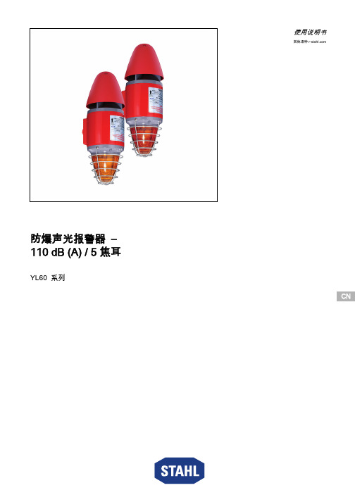
CN CN CN CN CN CN CN CN CN CN CN CN CN CN CN CN CN CN CN CN CN CN CN CNCN使用说明书其他语种 防爆声光报警器 – 110 dB (A) / 5 焦耳YL60 系列总体信息2防爆声光报警器 – 110 dB (A) / 5 焦耳YL60 系列内容目录1总体信息 ..............................................................................................................21.1制造商 .................................................................................................................21.2本使用说明书信息 ...............................................................................................31.3其他文件 ..............................................................................................................31.4标准和规定的符合性声明 ....................................................................................32图标说明 ..............................................................................................................32.1操作指南中的图标 ...............................................................................................32.2警告提示 ..............................................................................................................42.3设备上的图标 ......................................................................................................53安全说明 ..............................................................................................................53.1操作指南的保管 ...................................................................................................53.2安全使用 ..............................................................................................................53.3改装和改动 ..........................................................................................................54功能与设备结构 ...................................................................................................64.1功能 .....................................................................................................................65技术数据 ..............................................................................................................76仓储和运输 ..........................................................................................................97装配和安装 ........................................................................................................107.1尺寸信息/固定尺寸 ..........................................................................................107.2安装/拆卸、使用位置 .......................................................................................117.3安装 ...................................................................................................................218调试 ...................................................................................................................219运行 ...................................................................................................................229.1故障排除 ............................................................................................................2210保养、维护、修理 .............................................................................................2210.1保养 ...................................................................................................................2310.2修理 ...................................................................................................................2310.3退回 ...................................................................................................................2411清洁 ...................................................................................................................2412弃置处理 (2413)配件和备件 (24)1总体信息1.1制造商R. STAHL Schaltgeräte GmbH 照明和信号业务部门Nordstr. 1099427 Weimar 德国R. STAHL Schaltgeräte GmbH Am Bahnhof 3074638 Waldenburg 德国电话:传真网站:电子邮箱:+49 3643 4324+49 3643 ****************电话:传真网站:电子邮箱:+49 7942 943-0+49 7942 ****************282525 / YL6060300170 2018-04-13·BA00·III·zh·01图标说明3CNCNCNCNCNCNCNCNCN防爆声光报警器 – 110 dB (A) / 5 焦耳YL60 系列1.2本使用说明书信息ID编号:282525 / YL6060300170出版代码:2018-04-13·BA00·III·zh·01原版操作指南是英文版。
S3C44B0 中文数据手册
S3C44B0中文数据手册目录17.IIS (2)17.1概述 (2)17.2传输模式 (2)17.3音频串行接口格式 (3)17.4采集频率和主设备时钟 (4)17.5 IIS串行接口专用寄存器 (4)17.IIS17.1概述很多的数字音频系统进入了音频消费市场,包括音频压缩唱片,数字音频磁带,数字声音处理器,和数字声音TV。
S3C44B0X的IIS(内部声音集成电路)总线接口可以用来实现对外部8/16位立体声音频数字信号编解码器电路的接口功能,从而实现迷你型放音机和其它便携式的应用。
它支持IIS总线数据格式和MSB-justified数据格式。
IIS总线接口为FIFO 操作提供DMA传输模式,代替中断模式,它可以同时传送或接收数据。
特性:——兼容IIS,MSB-justified格式数据——每通道8/16位数据——每通道16,32,48fs(采样频率)串行位时钟——256,384fs主设备采样时钟频率——可编程的分频器提供给主设备时钟和编解码时钟——供给发送和接收用的32字节(2×16)的FIFO——普通传输模式和DMA传输模式17.2传输模式包括普通传输模式,和DMA传输模式。
普通传输模式IIS控制寄存器中有一个FIFO准备好标志位用于FIFO发送和接收。
当FIFO准备好发送数据,如果发送FIFO中不为空,FIFO准备好标志将被设置为1。
如果发送FIFO为空,FIFO准备好标志将被置0,当接收FIFO装满,接收FIFO准备好标志位被设置为0,这些标志可以决定CPU读写FIFO的时机。
串行数据就通过这种方式被发送或者接收的。
DMA传输模式在这个模式中,IIS的发送和接收FIFO操作都由DMA控制器来完成,在发送和接收模式中由FIFO准备好标志来自动产生DMA服务请求。
17.3音频串行接口格式IIS总线格式IIS总线具有4根信号线,包括串行数据输入(IISDI),串行数据输出(IISDO),左/右声道选择(IISLRCK),和串行数据时钟(IISCLK);产生IISLRCK和IISCLK的是主设备。
YL2410使用手册v2.0.1

YL2410使用手册第一章 YL2410开发板套件介绍 (2)1.1.YL2410开发板简介 (2)1.2.操作系统支持的驱动 (4)1.3.硬件资源分配 (4)1.3.1.地址空间分配以及片选信号定义 (4)1.3.2.接口资源及按键说明 (6)1.2.3.接口说明 (6)第二章 YL2410开发板使用 (7)2.1.启动Linux (7)2.2.启动WINCE (8)2.3.YL2410的BIOS功能说明 (10)2.4.非操作系统下的外围资源测试 (11)2.5.Linux操作系统下的外围资源测试 (15)2.6.用sjf2410工具将BIOS烧写到Nand Flash (17)2.7.用sjf2410工具将BIOS烧写到Nor Flash (20)第三章烧写和启动linux (22)3.1.烧写Linux内核 (22)3.2.烧写根文件系统 (24)3.3.启动Linux (25)3.3.1.通过BIOS的3号功能启动Linux (25)3.3.2.Linux的自启动 (25)第四章 烧写WINCE和启动WINCE (27)4.1.下载运行WINCE (27)4.2.烧写WINCE (29)4.3.自启动WINCE (30)附录一超级终端的设置 (32)附录二 DNW的设置 (32)第一章 YL2410开发板套件介绍1.1.YL2410开发板简介中央处理器── CPU: 三星S3C2410,主频203MHz;外部存储器──内存:64M字节;── NOR Flash:2M字节(SST39VF160或SST39VF1601);── NAND Flash:64M字节(K9F1208,用户可自己更换为16M、32M或128M的NandFlash)串口──两个五线异步串行口,波特率高达115200bps;──一个九线异步串行口,采用ST16C550扩展出来的,波特率高达1.5Mbps;网络接口──一个10M网口,采用CS8900Q3,带联接和传输指示灯;──一个100M网口,采用DM9000,带联接和传输指示灯;USB接口──一个USB1.1 HOST接口;──一个USB1.1 Device接口;红外通讯口──一个IRDA红外线数据通讯口;CAN总线接口──一个CAN总线接口,全面支持CAN2.0A和CAN2.0B协议;音频接口──采用IIS接口芯片UDA1341,一路立体声音频输出接口可接耳机或音箱;──支持录音,板子自带驻机体话筒可直接录音,另有一路话筒输入接口可接麦克风;存储接口──一个SD卡接口,可接256M SD卡;──一个CF卡接口(3.3V,接口信号均加了74LVTH162245驱动),工作在TrueIDE模式;──一个IDE接口(接口信号均加了74LVTH162245驱动),可直接挂接硬盘;LCD和触摸屏接口──板上集成了4线电阻式触摸屏接口的相关电路;──一个50芯LCD接口引出了LCD控制器的全部信号,并且这些信号引脚都加了74LVTH162245驱动,所以LCD输出更加稳定可靠;──支持黑白、4级灰度、16级灰度、256色、4096色STN液晶屏,尺寸从3.5寸到12.1寸,屏幕分辨率可达到1024×768象素;──支持黑白、4级灰度、16级灰度、256色、64K色、真彩色TFT液晶屏,尺寸从3.5寸到12.1寸,屏幕分辨率可达到1024×768象素;──标准配置为夏普256K色240x320/3.5英寸TFT液晶屏,带触摸屏;──板上引出一个5V电源输出接口,可为大尺寸TFT液晶屏的5V CCFL背光模块供电;VGA接口──一个标准VGA接口,可直接连接各种VGA接口的CRT显示器或液晶显示器,带对比度微调电位器;时钟源──内部实时时钟(带有后备锂电池);复位电路──一个复位按键,并采用专用复位芯片进行复位,稳定可靠;调试及下载接口──一个20芯Multi-ICE标准JTAG接口,支持SDT2.51,ADS1.2等调试;电源接口── 5V电源供电,带电源开关和指示灯;其他──八个小按键,四个高亮LED;──一个蜂鸣器(带使能控制的短路块);──一个可调电阻接到ADC引脚上用来验证模数转换;──一个50芯2毫米间距双排标准连接器用作扩展口,引出了地址线、数据线、读写、片选、中断、IO口、ADC、5V和3.3V电源、地等用户扩展可能用到的信号;;操作系统支持linux和用户光盘上提供的开发工具和源代码:1) ADS1.20安装程序(评估版);2) 使用SUPERJTAG并支持ADS1.20的JTAG调试软件ARM DEBUG;3) 烧写FLASH的工具软件SJF2410(包含NT/2000/XP解决方案);4) 串口工具软件sscom32.exe、dnw.exe、tftp.exe;5) 64K色(RGB565)图片字模软件;6) USB Device接口驱动程序;7) BIOS源代码(ADS1.20的项目文件);8)测试程序(ADS1.20的项目文件,包含全部源代码),包括如下测试:RTC实时时钟测试、按键测试(中断测试)、蜂鸣器测试、SD卡读写测试、音频录音放音测试、蜂鸣器测试(PWM测试)、ADC模数转换器测试、IIS音频播放wav音乐测试、IIS 音频录音测试、IrDA红外测试和、触摸屏测试、3.5寸夏普TFT液晶屏测试、CAN总线测试、VGA测试等等;9) Linux for S3c2410内核源码包以及编译工具,含CS8900和DM9000的EHTNENET端口驱动,UART驱动USB HOST & DEVICE驱动;10) 板级支持包BSP for S3c2410;11) 已经编译好并可在YL2410上运行的wince内核,基于优龙提供的BSP;12) 核心板和底板电路原理图(pdf格式);13) 开发板使用手册(pdf格式);14) 开发板上所用到的主要芯片手册;15)ADS使用、DNW串口使用和超级终端配置的一些多媒体演示;YL2410 套件包括:1) 一块已测试好的YL2410开发板(包括YL2410核心板与底板)2) YL2410用户光盘3)3.5" TFT 彩色LCD板一块,带触摸屏(选配)4)一个SUPER JTAG调试头(带20芯排线)5)一条并口线(一边是公头一边是母头,一对一)6)一条串口线(两边都是母头,交叉串口线)7)一条网线(交叉网线线)8) USB线一条9) 触摸笔一支(选配)10) 一个+5V直流电源11)一个包装盒1.2.操作系统支持的驱动支持Linux和WINCE操作系统。
- 1、下载文档前请自行甄别文档内容的完整性,平台不提供额外的编辑、内容补充、找答案等附加服务。
- 2、"仅部分预览"的文档,不可在线预览部分如存在完整性等问题,可反馈申请退款(可完整预览的文档不适用该条件!)。
- 3、如文档侵犯您的权益,请联系客服反馈,我们会尽快为您处理(人工客服工作时间:9:00-18:30)。
YL44B0X 开发板使用手册第一章 YL44B0X开发套件的组成..........................................................................................- 4 -1.1开发套件所提供的硬件详细清单.................................................................................- 4 -1.2 开发套件所提供的软件详细清单................................................................................- 5 -1.3 开发板接口和资源清单................................................................................................- 7 -1.4 板上硬件资源分配列表................................................................................................- 8 -1.4.1 系统片选及地址空间..........................................................................................- 8 -1.4.2 中断分配..............................................................................................................- 8 -1.4.3 系统板设定:......................................................................................................- 8 -1.5 板上接口和指示灯功能说明........................................................................................- 9 -1.5.1 接口板..................................................................................................................- 9 -第二章系统硬件描述..............................................................................................................- 10 -2.1 板上的电源电路..........................................................................................................- 10 -2.2 复位电路......................................................................................................................- 11 -2.3 CPU单元......................................................................................................................- 11 -2.4 SDRAM电路................................................................................................................- 12 -2.5 NORFLASH..................................................................................................................- 13 -2.6 RTL8019网络接口电路...............................................................................................- 14 -2.7 USBDEVICE(PDIUSBD12)接口电路...................................................................- 15 -2.8 异步串口接口电路......................................................................................................- 15 -2.9 LCD和触摸屏接口电路..............................................................................................- 16 -2.10 IIS音频输出电路.......................................................................................................- 17 -2.11 按键、蜂鸣器和LED电路......................................................................................- 18 -2.12 JTAG接口电路...........................................................................................................- 19 -2.13 IIC存储器(AT24C02)电路...................................................................................- 19 -第三章开发板资源测试方法和步骤......................................................................................- 20 -3.1 如何运行测试程序......................................................................................................- 20 -3.3 内存SDRAM读写自测试..........................................................................................- 22 -3.4 PWM脉宽调试和蜂鸣器测试....................................................................................- 23 -3.5 IIC总线EEPROM读写测试......................................................................................- 24 -3.6 模数转换器ADC测试................................................................................................- 25 -3.7 IIS音频播放WA V文件测试.......................................................................................- 26 -3.8 USB DEVICE(PDIUSBD12)测试..........................................................................- 27 -3.9 黑白STN液晶屏测试................................................................................................- 28 -3.10 黑白STN液晶屏显示英文字符测试......................................................................- 29 -3.11 4级灰度STN液晶屏测试.........................................................................................- 30 -3.12 16级灰度STN液晶屏测试......................................................................................- 31 -3.13 256色STN液晶屏测试............................................................................................- 32 -3.14 外部电平中断测试....................................................................................................- 33 -第四章 ARM编译调试开发平台的搭建................................................................................- 35 -4.1 安装ADS1.20编译调试环境.....................................................................................- 35 -4.2 安装并运行ARM-JTAG调试代理ARMJTAGDEBUGFINAL...............................- 35 -4.3 为ARM-JTAG调试代理正确配置AXD DEBUGGER............................................- 36 -4.4.使用SUPERJTAG在ADS1.20环境下进行仿真调试...........................................- 38 -第五章如何使用FLASHPGM快速烧写FLASH.................................................................- 40 -5.1计算机的设置...............................................................................................................- 40 -5.2 FLASHPGM的设置.....................................................................................................- 42 -5.3 设置通信端口..............................................................................................................- 43 -5.4 选择编程文件类型......................................................................................................- 44 -5.5 点击编程按钮..............................................................................................................- 44 -第六章 YL44B0X_BIOS的烧写与使用.................................................................................- 46 -6.1 YL44B0X_BIOS编译说明..........................................................................................- 46 -6.2 用BIOS通过网口烧写应用程序UC/OS-II到FLASH里......................................- 46 -6.3 用BIOS通过串口烧写应用程序UC/OS-II到FLASH里......................................- 48 -6.4 用BIOS通过网口来快速运行和调试应用程序UC/OS-II......................................- 49 -6.5 用BIOS通过串口来全速运行和调试应用程序UC/OS-II......................................- 50 -6.6 YL44B0X_BIOS命令简表..........................................................................................- 51 -6.7 YL44B0X_BIOS命令详解..........................................................................................- 52 -第七章建立UCLINUX 开发环境.........................................................................................- 56 -7.1 UCLINUX简介............................................................................................................- 56 -7.2 如何建立UCLINUX开发环境..................................................................................- 56 -7.3 UCLINUX内核的编译步骤........................................................................................- 57 -7.4 利用FTP下载应用程序到目标系统.........................................................................- 60 -7.4.1..............................................................................................................................- 60 -7.4.2..............................................................................................................................- 61 -7.4.3测试目标.............................................................................................................- 62 -7.4.4 进入SDRAM区域............................................................................................- 63 -7.4.5 FTP 192.168.3.80................................................................................................- 63 -7.4.7运行测试验.........................................................................................................- 67 -第八章 YL44B0X如何恢复到出厂设置................................................................................- 70 -8.1重新烧写BIOS.............................................................................................................- 70 -8.2 BIOS备份.....................................................................................................................- 70 -8.3........................................................................................................................................- 70 -第九章 YL44B0X如何烧写UCLINUX.................................................................................- 72 -9.1 烧写前准备..................................................................................................................- 72 -9.2 烧写中断向量表BOOT.BIN.......................................................................................- 72 -9.3 烧写UCLINUX内核:..............................................................................................- 72 -9.4 烧写UCLINUX根文件系统......................................................................................- 73 -9.5 输入命令MRUN就可运行UCLINUX.....................................................................- 74 -第十章 WFTPD配置(FTP服务器)...................................................................................- 75 -10.1运行WFTPD32.EXE..................................................................................................- 75 -10.2......................................................................................................................................- 75 -10.3......................................................................................................................................- 76 -10.4 建立新用户................................................................................................................- 77 -10.5 输入用户名efun........................................................................................................- 78 -10.6 输入密码efun 点击OK...........................................................................................- 79 -10.7......................................................................................................................................- 80 -第十一章相关的术语解释......................................................................................................- 81 -11.1 XMODEM协议..........................................................................................................- 81 -11.2 NAND FLASH和NOR FLASH详解.......................................................................- 81 -11.3 SDRAM存储器..........................................................................................................- 84 -第十二章 YL44B0X开发板使用FAQ...................................................................................- 85 -12.1 如何重新烧写BIOS?................................................................................................- 85 -12.2 为何超级终端不能输入?........................................................................................- 85 -12.3为何超级终端里,BIOS不接受AP等指令?........................................................- 85 -12.4 为何网络PING不通?.............................................................................................- 85 -12.5为何SUPERJTAG连不上目标板?.........................................................................- 85 -12.6 FLASHPGM无法进行FLASH烧写怎么办?........................................................- 85 -12.7开发板有时正常,有时不正常.................................................................................- 86 -第一章 YL44B0X开发套件的组成 1.1开发套件所提供的硬件详细清单YL44B0X 开发套件包括1) 一块已测试好的YL44B0X开发板2) 一张YL44B0X光盘3)一个SUPER JTAG调试头4)一条并口线(一边是公头一边是母头,一对一)5)一条交叉串口线(两边都是母头,一对一)6)一条网线(交叉线)7) 一个+9V直流电源8)一个包装盒1.2 开发套件所提供的软件详细清单1) ADS1.20安装程序(评估版);2) 使用SUPERJTAG并支持ADS1.20和SDT2.51的JTAG调试软件ARMJTAGDEBUGFINAL;3) 烧写FLASH的工具软件FLASHPGM2.2.4(评估版)以及适用于S3C44B0X的OCD配置文件;4) 串口工具软件sscom32.exe、dnw.exe、tftp.exe;5) LCD图片转换和字模转换工具软件UC-GUI-BITMAPCONVERT.EXE;6) YL44B0X BIOS源代码(ADS1.20的项目文件,包含RTL8019驱动和TFTP协议源码);7) YL44B0X测试程序(ADS1.20的项目文件,包含全部源代码),具有如下功能测试: 内存(SDRAM)读写自测试PWM输出蜂鸣器测试IIC总线EEPROM读写测试模数转换ADC测试IIS音频播放测试USB从设备PDIUSBD12测试黑白STN液晶屏测试STN屏字符串显示测试4级灰度STN液晶屏测试16级灰度液晶屏测试256色液晶屏测试外部中断测试以上测试均提供源码。