plc外文翻译.
PLC外文文献翻译

Programmable logic controllerA programmable logic controller (PLC) or programmable controller is a digital computer used for automation of electromechanical processes, such as control of machinery on factory assembly lines, amusement rides, or lighting fixtures. PLCs are used in many industries and machines. Unlike general-purpose computers, the PLC is designed for multiple inputs and output arrangements, extended temperature ranges, immunity to electrical noise, and resistance to vibration and impact. Programs to control machine operation are typically stored in battery-backed or non-volatile memory. A PLC is an example of a real time system since output results must be produced in response to input conditions within a bounded time, otherwise unintended operation will result.1.HistoryThe PLC was invented in response to the needs of the American automotive manufacturing industry. Programmable logic controllers were initially adopted by the automotive industry where software revision replaced the re-wiring of hard-wired control panels when production models changed.Before the PLC, control, sequencing, and safety interlock logic for manufacturing automobiles was accomplished using hundreds or thousands of relays, cam timers, and drum sequencers and dedicated closed-loop controllers. The process for updating such facilities for the yearly model change-over was very time consuming and expensive, as electricians needed to individually rewire each and every relay.In 1968 GM Hydramatic (the automatic transmission division of General Motors) issued a request for proposal for an electronic replacement for hard-wired relay systems. The winning proposal came from Bedford Associates of Bedford, Massachusetts. The first PLC, designated the 084 because it was Bedford Associates' eighty-fourth project, was the result. Bedford Associates started a new company dedicated to developing, manufacturing, selling, and servicing this new product: Modicon, which stood for MOdular DIgital CONtroller. One of the people who worked on that project was Dick Morley, who is considered to be the "father" of the PLC. The Modicon brand was sold in 1977 to Gould Electronics, and later acquired by German Company AEG and then by French Schneider Electric, the current owner. One of the very first 084 models built is now on display at Modicon's headquarters in North Andover, Massachusetts. It was presented to Modicon by GM, when the unit was retired after nearly twenty years of uninterrupted service. Modicon used the 84moniker at the end of its product range until the 984 made its appearance.The automotive industry is still one of the largest users of PLCs.2.DevelopmentEarly PLCs were designed to replace relay logic systems. These PLCs were programmed in "ladder logic", which strongly resembles a schematic diagram of relay logic. This program notation was chosen to reduce training demands for the existing technicians. Other early PLCs used a form of instruction list programming, based on a stack-based logic solver.Modern PLCs can be programmed in a variety of ways, from ladder logic to more traditional programming languages such as BASIC and C. Another method is State Logic, a very high-level programming language designed to program PLCs based on state transition diagrams.Many early PLCs did not have accompanying programming terminals that were capable of graphical representation of the logic, and so the logic was instead represented as a series of logic expressions in some version of Boolean format, similar to Boolean algebra. As programming terminals evolved, it became more common for ladder logic to be used, for the aforementioned reasons. Newer formats such as State Logic and Function Block (which is similar to the way logic is depicted when using digital integrated logic circuits) exist, but they are still not as popular as ladder logic.A primary reason for this is that PLCs solve the logic in a predictable and repeating sequence, and ladder logic allows the programmer (the person writing the logic) to see any issues with the timing of the logic sequence more easily than would be possible in other formats.2.1ProgrammingEarly PLCs, up to the mid-1980s, were programmed using proprietary programming panels or special-purpose programming terminals, which often had dedicated function keys representing the various logical elements of PLC programs. Programs were stored on cassette tape cartridges. Facilities for printing and documentation were very minimal due to lack of memory capacity. The very oldest PLCs used non-volatile magnetic core memory.More recently, PLCs are programmed using application software on personal computers. The computer is connected to the PLC through Ethernet, RS-232, RS-485 or RS-422 cabling. The programming software allows entry and editing of the ladder-style logic. Generally the software provides functions for debugging andtroubleshooting the PLC software, for example, by highlighting portions of the logic to show current status during operation or via simulation. The software will upload and download the PLC program, for backup and restoration purposes. In some models of programmable controller, the program is transferred from a personal computer to the PLC though a programming board which writes the program into a removable chip such as an EEPROM or EPROM.3.FunctionalityThe functionality of the PLC has evolved over the years to include sequential relay control, motion control, process control, distributed control systems and networking. The data handling, storage, processing power and communication capabilities of some modern PLCs are approximately equivalent to desktop computers. PLC-like programming combined with remote I/O hardware, allow a general-purpose desktop computer to overlap some PLCs in certain applications. Regarding the practicality of these desktop computer based logic controllers, it is important to note that they have not been generally accepted in heavy industry because the desktop computers run on less stable operating systems than do PLCs, and because the desktop computer hardware is typically not designed to the same levels of tolerance to temperature, humidity, vibration, and longevity as the processors used in PLCs. In addition to the hardware limitations of desktop based logic, operating systems such as Windows do not lend themselves to deterministic logic execution, with the result that the logic may not always respond to changes in logic state or input status with the extreme consistency in timing as is expected from PLCs. Still, such desktop logic applications find use in less critical situations, such as laboratory automation and use in small facilities where the application is less demanding and critical, because they are generally much less expensive than PLCs.In more recent years, small products called PLRs (programmable logic relays), and also by similar names, have become more common and accepted. These are very much like PLCs, and are used in light industry where only a few points of I/O (i.e. a few signals coming in from the real world and a few going out) are involved, and low cost is desired. These small devices are typically made in a common physical size and shape by several manufacturers, and branded by the makers of larger PLCs to fill out their low end product range. Popular names include PICO Controller, NANO PLC, and other names implying very small controllers. Most of these have between 8 and 12 digital inputs, 4 and 8 digital outputs, and up to 2 analog inputs. Size is usuallyabout 4" wide, 3" high, and 3" deep. Most such devices include a tiny postage stamp sized LCD screen for viewing simplified ladder logic (only a very small portion of the program being visible at a given time) and status of I/O points, and typically these screens are accompanied by a 4-way rocker push-button plus four more separate push-buttons, similar to the key buttons on a VCR remote control, and used to navigate and edit the logic. Most have a small plug for connecting via RS-232 or RS-485 to a personal computer so that programmers can use simple Windows applications for programming instead of being forced to use the tiny LCD and push-button set for this purpose. Unlike regular PLCs that are usually modular and greatly expandable, the PLRs are usually not modular or expandable, but their price can be two orders of magnitude less than a PLC and they still offer robust design and deterministic execution of the logic.4.PLC Topics4.1.FeaturesThe main difference from other computers is that PLCs are armored for severe conditions (such as dust, moisture, heat, cold) and have the facility for extensive input/output (I/O) arrangements. These connect the PLC to sensors and actuators. PLCs read limit switches, analog process variables (such as temperature and pressure), and the positions of complex positioning systems. Some use machine vision. On the actuator side, PLCs operate electric motors, pneumatic or hydraulic cylinders, magnetic relays, solenoids, or analog outputs. The input/output arrangements may be built into a simple PLC, or the PLC may have external I/O modules attached to a computer network that plugs into the PLC.4.2System scaleA small PLC will have a fixed number of connections built in for inputs and outputs. Typically, expansions are available if the base model has insufficient I/O.Modular PLCs have a chassis (also called a rack) into which are placed modules with different functions. The processor and selection of I/O modules is customised for the particular application. Several racks can be administered by a single processor, and may have thousands of inputs and outputs. A special high speed serial I/O link is used so that racks can be distributed away from the processor, reducing the wiring costs for large plants.4.3User interfacePLCs may need to interact with people for the purpose of configuration, alarmreporting or everyday control.A simple system may use buttons and lights to interact with the user. Text displays are available as well as graphical touch screens. More complex systems use a programming and monitoring software installed on a computer, with the PLC connected via a communication interface.4.4CommunicationsPLCs have built in communications ports, usually 9-pin RS-232, but optionally EIA-485 or Ethernet. Modbus, BACnet or DF1 is usually included as one of the communications protocols. Other options include various fieldbuses such as DeviceNet or Profibus. Other communications protocols that may be used are listed in the List of automation protocols.Most modern PLCs can communicate over a network to some other system, such as a computer running a SCADA (Supervisory Control And Data Acquisition) system or web browser.PLCs used in larger I/O systems may have peer-to-peer (P2P) communication between processors. This allows separate parts of a complex process to have individual control while allowing the subsystems to co-ordinate over the communication link. These communication links are also often used for HMI devices such as keypads or PC-type workstations.4.5ProgrammingPLC programs are typically written in a special application on a personal computer, then downloaded by a direct-connection cable or over a network to the PLC. The program is stored in the PLC either in battery-backed-up RAM or some other non-volatile flash memory. Often, a single PLC can be programmed to replace thousands of relays.Under the IEC 61131-3 standard, PLCs can be programmed using standards-based programming languages. A graphical programming notation called Sequential Function Charts is available on certain programmable controllers. Initially most PLCs utilized Ladder Logic Diagram Programming, a model which emulated electromechanical control panel devices (such as the contact and coils of relays) which PLCs replaced. This model remains common today.IEC 61131-3 currently defines five programming languages for programmable control systems: FBD (Function block diagram), LD (Ladder diagram), ST (Structured text, similar to the Pascal programming language), IL (Instruction list,similar to assembly language) and SFC (Sequential function chart). These techniques emphasize logical organization of operations.While the fundamental concepts of PLC programming are common to all manufacturers, differences in I/O addressing, memory organization and instruction sets mean that PLC programs are never perfectly interchangeable between different makers. Even within the same product line of a single manufacturer, different models may not be directly compatible.5.PLC compared with other control systemsPLCs are well-adapted to a range of automation tasks. These are typically industrial processes in manufacturing where the cost of developing and maintaining the automation system is high relative to the total cost of the automation, and where changes to the system would be expected during its operational life. PLCs contain input and output devices compatible with industrial pilot devices and controls; little electrical design is required, and the design problem centers on expressing the desired sequence of operations. PLC applications are typically highly customized systems so the cost of a packaged PLC is low compared to the cost of a specific custom-built controller design. On the other hand, in the case of mass-produced goods, customized control systems are economic due to the lower cost of the components, which can be optimally chosen instead of a "generic" solution, and where the non-recurring engineering charges are spread over thousands or millions of units.For high volume or very simple fixed automation tasks, different techniques are used. For example, a consumer dishwasher would be controlled by an electromechanical cam timer costing only a few dollars in production quantities.A microcontroller-based design would be appropriate where hundreds or thousands of units will be produced and so the development cost (design of power supplies, input/output hardware and necessary testing and certification) can be spread over many sales, and where the end-user would not need to alter the control. Automotive applications are an example; millions of units are built each year, and very few end-users alter the programming of these controllers. However, some specialty vehicles such as transit busses economically use PLCs instead of custom-designed controls, because the volumes are low and the development cost would be uneconomic.Very complex process control, such as used in the chemical industry, may require algorithms and performance beyond the capability of even high-performance PLCs. Very high-speed or precision controls may also require customized solutions; forexample, aircraft flight controls.Programmable controllers are widely used in motion control, positioning control and torque control. Some manufacturers produce motion control units to be integrated with PLC so that G-code (involving a CNC machine) can be used to instruct machine movements.PLCs may include logic for single-variable feedback analog control loop, a "proportional, integral, derivative" or "PID controller". A PID loop could be used to control the temperature of a manufacturing process, for example. Historically PLCs were usually configured with only a few analog control loops; where processes required hundreds or thousands of loops, a distributed control system (DCS) would instead be used. As PLCs have become more powerful, the boundary between DCS and PLC applications has become less distinct.PLCs have similar functionality as Remote Terminal Units. An RTU, however, usually does not support control algorithms or control loops. As hardware rapidly becomes more powerful and cheaper, RTUs, PLCs and DCSs are increasingly beginning to overlap in responsibilities, and many vendors sell RTUs with PLC-like features and vice versa. The industry has standardized on the IEC 61131-3 functional block language for creating programs to run on RTUs and PLCs, although nearly all vendors also offer proprietary alternatives and associated development environments.6.Digital and analog signalsDigital or discrete signals behave as binary switches, yielding simply an On or Off signal (1 or 0, True or False, respectively). Push buttons, limit switches, and photoelectric sensors are examples of devices providing a discrete signal. Discrete signals are sent using either voltage or current, where a specific range is designated as On and another as Off. For example, a PLC might use 24 V DC I/O, with values above 22 V DC representing On, values below 2VDC representing Off, and intermediate values undefined. Initially, PLCs had only discrete I/O.Analog signals are like volume controls, with a range of values between zero and full-scale. These are typically interpreted as integer values (counts) by the PLC, with various ranges of accuracy depending on the device and the number of bits available to store the data. As PLCs typically use 16-bit signed binary processors, the integer values are limited between -32,768 and +32,767. Pressure, temperature, flow, and weight are often represented by analog signals. Analog signals can use voltage or current with a magnitude proportional to the value of the process signal. For example,an analog 0 - 10 V input or 4-20 mA would be converted into an integer value of 0 - 32767.。
PLC毕业设计外文翻译3

学校名称外文翻译专业:班级学号:学生姓名:指导教师:二〇一一年六月学校名称本科生毕业设计原文1:Programmable logic controllers 译文1:可编程逻辑控制器原文2:Foundation of PLC译文2:PLC基础专业班级:学生姓名:指导教师:学院:2011年6月原文1:Programmable logic controllersProgrammable logic controller(PLC) is eight 10- Year on behalf new generation industry that develop the control equip, and is an automatic control, calculator with the thing that the correspondence technique combine together, and is a the spot equipments for exclusively used foring the industry production line controling. Make the PLC there is characteristics of obvious oneself on the design with the long- term and continuous that circulate because of the special of the complexity, usage environment of the control object: The dependable is high, and the adaptability is wide, and have to correspond by letter the function, and weave the the convenience, construction mold piece . Gather the the control in the modern in the system, the PLC have already become a kind of importance of basic control unit, control the realm the inside in the industry applied the foreground is very and extensive.A programmable logic controller(PLC) is a solid-state devide used to control machine motion or process operation by means of a stored program. The PLC sends output control signals and receives input signals through input/output (I/O) devices.A PLC controls outputs in response to stimuli at the inputs according to the logic prescribed by the stored program.The inputs are made up of limit switches,pushbuttons,thumbwheels, switches,pulses,analog signals,ASCII serial data,and binary or BCD data from absolute position encoders.The outputs are voltage or current levers to drive end devices such as lolenids,motor staters,relays,lights,and so on.Other output devices such include analog devices,digital BCD displays,ASCII compatible devices,servo variable-speed drives,and even computers.Programmable controllers were developed(circa in 1968) when General Motors Corp,and other automobile manufacturers were experimenting to see if there might be an alterantive to scrapping all their hardwired control panels of machine tools and other production equipment during a model changeover.This annual tradition was necessary because rewiring of the panels was more expensive than buying new oens.The automotive companies approached a number of control equipment manufacturers and asked them to develop a control system that would have a longer productive life without major rewiring,but would still be understandable to and repairable by plant personnel.The new product wa namd a“programmable controller”.The processor part of the PLC contains a central processing unit and memory.The central proce ssing unit(CPU) is the“trafficdirector”of the processor,the memory stores ing into the processor are the electrical signals from the input devices,as conditioned by the input module to voltage levels acceptable to processor logic.The processor scans the state of I/O and updates outputs based on instructions stored in the memory of the PLC.For example,the processor may be programmed so that if an input connected to a limit switch is true(1imit switch closed),then a corresponding output wired to an output module is to be energized.This output might be asolenoid for example.The processor remembers this command through its memory and compares on each scan to see if that limit is, in fact ,closed. If it is closed, the processor energizes the solenoid by turning on the output module.The output device, such as a solenoid or motor stater,is wired to an output mofule’s terminal,and itreceives its shift signal from the processor, in effect the peocessor is performing a long and complicated series of logic decisions. The PLC performs such decisions sequentially and in accordance with the stored program.similarly, analog I/O allows the processor to make decisions based on the magnitude of a signal, rather than just if is on or off.For example,the processor may be programmes toencrease or decrease the steam flow to a boiler(analog output) based on a comparison of the actual temperature in the boiler(analog input) to the desired temperature. this is often performed by utilizing the built-in PID(proportional,integral,derivative) capabilities of the processor.Proper power to the programmable controller is critical. Today’s systems are available in a wide variety of electrical configurations. Virtually all are designed for use in single-phase power systems, and most are now beginning to be offered with the optional ability to operate in a DC supply environment. AC designs are offered in either single voltage supplies, such as 115 or 230V AC; while some can be configured as either through a selection made on the power supply. Proper grounding of the power supply connection is required for a safe installation. Some programmable controller designs have individual grounding connections from rack to face- plates and other system components, so care must be taken to follow well electrical practice in system grounding during electricalinstallation. In certain applications, a 24 or 120 V DC power supply is required. This is common for installations that axe made where no AC power is available, such as remote electrical generation stations. It is also found where AC power is unreliable and where loss of control is considered an unacceptable situationEven the best of today' s well-designed and manufactured programmable controllers require occasional preventative maintenance and repair. This section looks at some of the tools provided by the manufacturer and techniques for general maintenance.Most of the medium- and large-sized programmable controller systems available today are designed to be maintained by individuals with a wide variety of skills, without the benefit of in-depth formal training of this piece of equipment. This is accomplished in the design by providing individual modules of functionality installed in a chassis serviced from the front (all module types including power supplies). Front access is critical to proper maintenance. This allows easy inspection and replacement of the suspected bad module. Module health is determined by inspecting the LED indicators normally provided on the front of each module. Typical indicators will be on or off depending on the design and individual condition of the module in question. Various CPU and I/O modules will have indicators showing I/O control communications status, memory integrity, power supply tolerance check, scan integrity, and others. On future controller designs, and even today on a few systems, it is likely that English language messages will be displayed on the controller advising the user or maintenance personnel that a particular failure has occurred and recommended actions to take.The modular design and diagnostic indicators are, of course, important, but would be quite useless without well designed documentation provided by the manufacturer for the programmable controller system in question. Proper documentation will have sections dedicated to each major subsystem including CPU, I/O, and programming device. Each should explain in depth the stop-by-stop inspection of the system. All possible combinations of failure mode should be listed, along with suggested actions for repair. This will most often involve only the substitution of a re- placement board for the suspected failed unit. The user is urged to purchase a set of spare modules for the system in question as recommended by the manufacturer. This is normally, at a minimum, a single replacement module for each CPU and programming device serviceable module, and spare I/O modules equal to 10% of the number in the system.Because a PLC is “software based”,its control logic functions can be changed byreprogramming its memory. Keyboard programming devices facilitate entry of the revised program, which can be designed to cause an existing machine or process to operate in a different sequence or to respond to different levels of, or combinations of stimuli .Hardware modifications are needed only if additional, changed, or relocated input/output devices are involved.Programmable controller memory is formatted into bits, bytes, and words of memory.A bit is a single storage element for either a zero or a one. A byte consists of eight bits, and a word (normally) consists of 16 bits, or two bytes. Some systems still use a word length of eight bits, but most have adopted a 16 bit word, even though they may use an 8 bit microprocessor.Depending on the specific design of the programmable controller, it will have a stated memory capacity. This is an indication, although not the only one, of the capability and power of the system. Medium and large controllers are normally expandable from one memory size to their maximum size. Small controllers are normally fixed in their memory size. Size of the memory capacity must be examined relative to the word size ( 8 bit or 16 bit) and utilization. While it is clear that twice the information can be stored in a 16 bit word than in an 8 bit word, it may not be immediately clear that some controllers utilize memory more efficiently than others. For example, a normally open contact and its associated reference address (e.g. Input 1), may use in 8 bit byte each for storage. Combined, they consume one 16 bit word. Some controllers may use more memory than this for these instructions or others. In a large program, these inefficiencies can build on each other to cause a poor utilization of the system memory. A careful analysis of the various programmable controller models is required to assess utilization efficiency. Normal practice calls for an additional 20% - 40% of memory size to be specified to allow for modifications and later expansion. This analysis, combined with knowledge of the application needs, will allow for an intelligent choice of programmable controller.In fine, PLC conduct and actions the spot control equipments, can dependable,accurately complete the control the operation, and can pass with upper grade work machine correspondence, constitute the distribute type the system to complete to control the industry equip. system control request, is a modern industry control the inside compare forerunner’s control project, and apply the foreground to is extensive.译文1:可编程逻辑控制器可编程逻辑控制器(PLC)是八十年代发展起来的新一代工业控制装置,是自动控制、计算机和通信技术相结合的产物,是一种专门用于工业生产过程控制的现场设备。
plc外文翻译
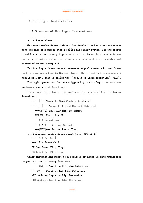
1 Bit Logic Instructions1.1 Overview of Bit Logic Instructions1.1.1 DescriptionBit logic instructions work with two digits, 1 and 0. These two digits form the base of a number system called the binary system. The two digits 1 and 0 are called binary digits or bits. In the world of contacts and coils, a 1 indicates activated or energized, and a 0 indicates not activated or not energized.The bit logic instructions interpret signal states of 1 and 0 and combine them according to Boolean logic. These combinations produce a result of 1 or 0 that is called the “result of logic operation” (RLO).The logic operations that are triggered by the bit logic instructions perform a variety of functions.There are bit logic instructions to perform the following functions:---| |--- Normally Open Contact (Address)---| / |--- Normally Closed Contact (Address)---(SAVE) Save RLO into BR MemoryXOR Bit Exclusive OR---( ) Output Coil---( # )--- Midline Output---|NOT|--- Invert Power FlowThe following instructions react to an RLO of 1:---( S ) Set Coil---( R ) Reset CoilSR Set-Reset Flip FlopRS Reset-Set Flip FlopOther instructions react to a positive or negative edge transition to perform the following functions:---(N)--- Negative RLO Edge Detection---(P)--- Positive RLO Edge DetectionNEG Address Negative Edge DetectionPOS Address Positive Edge DetectionImmediate ReadImmediate Write1.2 ---| |--- Normally Open Contact (Address)1.2.1 Symbol<address>---| |---Parameter Data Type Memory Area Description<address>BOOL I, Q, M, L, D, T, C Checked bit1.2.2 Description---| |--- (Normally Open Contact) is closed when the bit value stored at the specified <address>is equal to "1". When the contact is closed, ladder rail power flows across the contact and the result of logic operation (RLO) = "1".Otherwise, if the signal state at the specified <address>is "0", the contact is open. When the contact is open, power does not flow across the contact and the result of logic operation (RLO) = "0".When used in series, ---| |--- is linked to the RLO bit by AND logic. When used in parallel, it is linked to the RLO by OR logic.1.2.3 Status wordBR CC1CC0OV OS OR STA RLO/ FCwrites:-----x x x11.2.4 ExamplePower flows if one of the following conditions exists:The signal state is "1" at inputs I0.0 and I0.1 Or the signal state is "1" at input I0.2.1.3 ---| / |--- Normally Closed Contact (Address)1.3.1 Symbol<address>---| / |---Parameter Data Type Memory Area Description<address>BOOL I, Q, M, L, D, T, C Checked bit1.3.2 Description---| / |--- (Normally Closed Contact) is closed when the bit value stored at the specified <address>is equal to "0". When the contact is closed, ladder rail power flows across the contact and the result of logic operation (RLO) = "1".Otherwise, if the signal state at the specified <address> is "1", the contact is opened. When the contact is opened, power does not flow across the contact and the result of logic operation (RLO) = "0".When used in series, ---| / |--- is linked to the RLO bit by AND logic. When used in parallel, it is linked to the RLO by OR logic.1.3.3 Status wordBR CC1CC0OV OS OR STA RLO/ FCwrites:-----x x x11.3.4 ExamplePower flows if one of the following conditions exists:The signal state is "1" at inputs I0.0 and I0.1 Or the signal state is "1" at input I0.21.4 XOR Bit Exclusive ORFor the XOR function, a network of normally open and normally closed contacts must be created as shown below.1.4.1 SymbolsParameter Data Type Memory Area Description<address1>BOOL I, Q, M, L, D, T, C Scanned bit<address2>BOOL I, Q, M, L, D, T, C Scanned bit1.4.2 DescriptionXOR(Bit Exclusive OR) creates an RLO of "1" if the signal state of the two specified bits is different.1.4.3 ExampleThe output Q4.0 is "1" if (I0.0 = "0" AND I0.1 = "1") OR (I0.0 = "1" AND I0.1 = "0").1.5 --|NOT|-- Invert Power Flow1.5.1 Symbol---|NOT|---1.5.2 Description---|NOT|---(Invert Power Flow) negates the RLO bit.1.5.3 Status wordBR CC1CC0OV OS OR STA RLO/ FCwrites:------1x-1.5.4 ExampleThe signal state of output Q4.0 is "0" if one of the following conditions exists:The signal state is "1" at input I0.0 Or the signal state is "1" at inputs I0.1 and I0.2.1.6 ---( ) Output Coil1.6.1 Symbol<address>---( )Parameter Data Type Memory Area Description<address>BOOL I, Q, M, L, D Assigned bit1.6.2 Description---( ) (Output Coil) works like a coil in a relay logic diagram. If there is power flow to the coil (RLO = 1), the bit at location <address> is set to "1". If there is no power flow to the coil (RLO = 0), the bit at location <address>is set to "0". An output coil can only be placed at the right end of a ladder rung. Multiple output elements (max.16) are possible (see example). A negated output can be created by using the ---|NOT|--- (invert power flow) element.1.6.3 MCR (Master Control Relay) dependencyMCR dependency is activated only if an output coil is placed inside an active MCR zone. Within an activated MCR zone, if the MCR is on and there is power flow to an output coil , the addressed bit is set to the current status of power flow. If the MCR is off, a logic "0" is written to the specified address regardless of power flow status.1.6.4 Status wordBR CC1CC0OV OS OR STA RLO/ FCwrites:-----0x-01.6.5 ExampleThe signal state of output Q4.0 is "1" if one of the following conditions exists:The signal state is "1" at inputs I0.0 AND I0.1 OR the signal state is "0" at input I0.2.The signal state of output Q4.1 is "1" if one of the following conditions exists:The signal state is "1" at inputs I0.0 AND I0.1 OR the signal state is "0" at input I0.2 AND "1" at input I0.3If the example rungs are within an activated MCR zone:When MCR is on, Q4.0 and Q4.1 are set according to power flow status as described above.When MCR is off (=0), Q4.0 and Q4.1 are reset to 0 regardless of power flow.1.7 ---( # )--- Midline Output1.7.1 Symbol<address>--( # )---Parameter Data Type Memory Area Description<address>BOOL I, Q, M, *L, D Assigned bit* An L area address can only be used if it is declared TEMP in the variable declaration table of a logic block (FC, FB, OB).1.7.2 Description---( # )--- (Midline Output) is an intermediate assigning element which saves the RLO bit (power flow status) to a specified <address>. The midline output element saves the logical result of the preceding branch elements. In series with other contacts, ---( # )--- is inserted like a contact. A ---( # )--- element may never be connected to the power rail or directly after a branch connection or at the end of a branch. A negated ---( # )--- can be created by using the ---|NOT|--- (invert power flow) element.1.7.3 MCR (Master Control Relay) dependencyMCR dependency is activated only if a midline output coil is placed inside an active MCR zone. Within an activated MCR zone, if the MCR is on and there is power flow to a midline output coil; the addressed bit is set to the current status of power flow. If the MCR is off, a logic "0" is written to the specified address regardless of power flow status.1.7.4 Status wordBR CC1CC0OV OS OR STA RLO/ FCwrites:-----0x-11.7.5 ExampleM 0.0 has the RLO:M 1.1 has the RLO:M 2.2 has the RLO of the entire bit logic combination.1.8 ---( R ) Reset Coil1.8.1 Symbol<address>---( R )Parameter Data Type Memory Area Description<address>BOOL I, Q, M, L, D, T, C Reset bit1.8.2 Description---( R )(Reset Coil) is executed only if the RLO of the preceding instructions is "1" (power flows to the coil). If power flows to the coil (RLO is "1"), the specified <address>of the element is reset to "0". A RLO of "0" (no power flow to the coil) has no effect and the state of the element's specified address remains unchanged. The <address>may also be a timer (T no.) whose timer value is reset to "0" or a counter (C no.) whose counter value is reset to "0".1.8.3 MCR (Master Control Relay) dependencyMCR dependency is activated only if a reset coil is placed inside an active MCR zone. Within an activated MCR zone, if the MCR is on and there is power flow to a reset coil; the addressed bit is reset to the "0" state. If the MCR is off, the current state of the element's specified address remains unchanged regardless of power flow status.1.8.4 Status wordBR CC1CC0OV OS OR STA RLO/ FCwri-----0x-0tes:1.8.5 ExampleNetwork 1Network 2Network 3The signal state of output Q4.0 is reset to "0" if one of the following conditions exists:The signal state is "1" at inputs I0.0 and I0.1 Or the signal state is "0" at input I0.2.If the RLO is "0", the signal state of output Q4.0 remains unchanged.The signal state of timer T1 is only reset if:the signal state is "1" at input I0.3.The signal state of counter C1 is only reset if:the signal state is "1" at input I0.4.If the example rungs are within an activated MCR zone:When MCR is on, Q4.0, T1, and C1 are reset as described above.When MCR is off, Q4.0, T1, and C1 are left unchanged regardless of RLO state (power flow status).1 位逻辑指令1.1 位逻辑指令概述1.1.1 描述位逻辑指令使用两个数字,1和0。
电气工程及其自动化专业_外文文献_英文文献_外文翻译_plc方面.
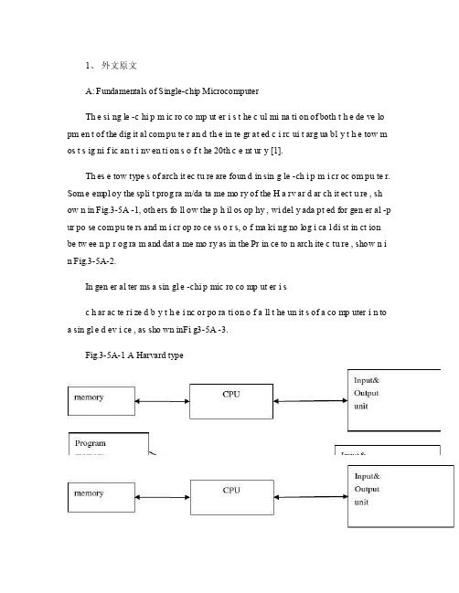
1、外文原文A: Fundamentals of Single-chip MicrocomputerTh e si ng le -c hi p m ic ro co mp ut er i s t he c ul mi na ti on of both t h e de ve lo pm en t of the dig it al com pu te r an d th e in te gr at ed c i rc ui t arg ua bl y t h e tow m os t s ig ni f ic an t i nv en ti on s o f t he 20th c e nt ur y [1].Th es e tow type s of arch it ec tu re are foun d in sin g le -ch i p m i cr oc om pu te r. Som e empl oy the spli t prog ra m/da ta me mo ry of the H a rv ar d ar ch it ect u re , sh ow n in Fig.3-5A -1, oth ers fo ll ow the p h il os op hy , wi del y ada pt ed for gen er al -p ur po se com pu te rs and m i cr op ro ce ss o r s, o f ma ki ng no log i ca l di st in ct ion be tw ee n p r og ra m and dat a me mo ry as in the Pr in ce to n arch ite c tu re , show n i n Fig.3-5A-2.In gen er al ter ms a sin gl e -chi p mic ro co mp ut er i sc h ar ac te ri zed b y t he i nc or po ra ti on of a ll t he un it s of a co mp uter i n to a sin gl e d ev i ce , as sho wn inFi g3-5A -3.Fig.3-5A-1 A Harvard typeFig.3-5A-2. A conventional Princeton computerFig3-5A-3. Principal features of a microcomputerRead only memory (ROM.R OM is usua ll y for the pe rm an ent,n o n-vo la ti le stor a ge of an app lic a ti on s pr og ra m .M an ym i cr oc om pu te rs and m are inte nd e d for high -v ol um e ap pl ic at ions a n d he nc e t h e eco n om ic al man uf act u re of th e de vic e s re qu ir es t h at t he cont en t s o f t he prog ra m me m or y be co mm it t ed perm a ne ntly d u ri ng the man ufa c tu re of ch ip s .Cl ea rl y, thi s im pl ie s a r i go ro us app ro ach to ROM cod e deve l op me nt sin ce cha ng es can not b e mad e afte r manu f a c tu re .Th is dev e lo pm en t proc ess may invo lv e e m ul at io n us in g aso ph is ti ca te d de ve lo pm en t sy ste m wit h a h a rd wa re emu la tio n cap ab il it y as w el l as the use o f po we rf ul s o ft wa re too ls.So me man uf act u re rs pro vi de add it io na l RO M opt i on s by i n cl ud in g in their ra n ge dev ic es wit h (or int en de d fo r use wit h u s er pro gr am ma ble me mo ry. Th e sim p le st of th es e is usu al ly d e vi ce whi ch can op er at e in a micro p ro ce ssor mod e by usi ng som e o f the inp ut /outp u t li ne s as an ad dr es s an d da ta b us fora c ce ss in g ex te rna l mem or y. Thi s t y pe of de vi ce can beh av ef u nc ti on al ly as th e sing le chip mi cr oc om pu te r from whi ch it is d e ri ve d al be it wit h re st ri ct ed I/O and a mod if ied ex te rn al c i rc ui t. The use of thes e d ev ic es is com mo n eve n in prod uc ti on c i rc ui ts wher e t he vo lu me does no tj us ti f y t h e d ev el o pm en t c osts o f c us to m o n -ch i p R OM [2];t he re c a n s ti ll bea s ignif i ca nt saving i n I /O and o th er c h ip s com pa re d to a conv en ti on al mi c ro pr oc es sor b a se d ci rc ui t. Mor e ex ac t re pl ace m en t fo r RO M dev i ce s ca n be o b ta in ed in th e fo rm of va ri an ts w it h 'p ig gy -b ack 'E P RO M(Er as ab le pro gr am ma bl e ROM s oc ke ts or dev ic e s with EPROM i n st ea d o f RO M 。
可编程控制器外文翻译、中英文翻译、外文文献翻译
毕业设计中英文翻译院系专业班级姓名学号指导教师20**年 4 月Programmable Logic Controllers (PLC)1、MotivationProgrammable Logic Controllers (PLC), a computing device invented by Richard E. Morley in 1968, have been widely used in industry including manufacturing systems, transportation systems, chemical process facilities, and many others. At that time, the PLC replaced the hardwired logic with soft-wired logic or so-called relay ladder logic (RLL), a programming language visually resembling the hardwired logic, and reduced thereby the configuration time from 6 months down to 6 days [Moody and Morley, 1999].Although PC based control has started to come into place, PLC based control will remain the technique to which the majority of industrial applications will adhere due to its higher performance, lower price, and superior reliability in harsh environments. Moreover, according to a study on the PLC market of Frost and Sullivan [1995], an increase of the annual sales volume to 15 million PLCs per year with the hardware value of more than 8 billion US dollars has been predicted, though the prices of computing hardware is steadily dropping. The inventor of the PLC, Richard E Morley, fairly considers the PLC market as a 5-billion industry at the present time.Though PLCs are widely used in industrial practice, the programming of PLC based control systems is still very much relying on trial-and-error. Alike software engineering, PLC software design is facing the software dilemma or crisis in a similar way. Morley himself emphasized this aspect most forcefully by indicating [Moody and Morley, 1999, p. 110]:`If houses were built like software projects, a single woodpecker could destroy civilization.”Particularly, practical problems in PLC programming are to eliminate software bugs and to reduce the maintenance costs of old ladder logic programs. Though the hardware costs of PLCs are dropping continuously, reducing the scan time of the ladder logic is still an issue in industry so that low-cost PLCs can be used.In general, the productivity in generating PLC is far behind compared to other domains, for instance, VLSI design, where efficient computer aided design tools are in practice. Existent software engineering methodologies are not necessarily applicable to the PLC basedsoftware design because PLC-programming requires a simultaneous consideration of hardware and software. The software design becomes, thereby, more and more the major cost driver. In many industrial design projects, more than SO0/a of the manpower allocated for the control system design and installation is scheduled for testing and debugging PLC programs [Rockwell, 1999].In addition, current PLC based control systems are not properly designed to support the growing demand for flexibility and reconfigurability of manufacturing systems. A further problem, impelling the need for a systematic design methodology, is the increasing software complexity in large-scale projects.PLCs (programmable logic controllers) are the control hubs for a wide variety of automated systems and processes. They contain multiple inputs and outputs that use transistors and other circuitry to simulate switches and relays to control equipment. They are programmable via software interfaced via standard computer interfaces and proprietary languages and network options.Programmable logic controllers I/O channel specifications include total number of points, number of inputs and outputs, ability to expand, and maximum number of channels. Number of points is the sum of the inputs and the outputs. PLCs may be specified by any possible combination of these values. Expandable units may be stacked or linked together to increase total control capacity. Maximum number of channels refers to the maximum total number of input and output channels in an expanded system. PLC system specifications to consider include scan time, number of instructions, data memory, and program memory. Scan time is the time required by the PLC to check the states of its inputs and outputs. Instructions are standard operations (such as math functions) available to PLC software. Data memory is the capacity for data storage. Program memory is the capacity for control software.Available inputs for programmable logic controllers include DC, AC, analog, thermocouple, RTD, frequency or pulse, transistor, and interrupt inputs. Outputs for PLCs include DC, AC, relay, analog, frequency or pulse, transistor, and triac. Programming options for PLCs include front panel, hand held, and computer.Programmable logic controllers use a variety of software programming languages for control. These include IEC 61131-3, sequential function chart (SFC), function block diagram (FBD), ladder diagram (LD), structured text (ST), instruction list (IL), relay ladder logic (RLL), flow chart, C, and Basic. The IEC 61131-3 programming environment provides support for five languages specified by the global standard: Sequential Function Chart,Function Block Diagram, Ladder Diagram, Structured Text, and Instruction List. This allows for multi-vendor compatibility and multi-language programming. SFC is a graphical language that provides coordination of program sequences, supporting alternative sequence selections and parallel sequences. FBD uses a broad function library to build complex procedures in a graphical format. Standard math and logic functions may be coordinated with customizable communication and interface functions. LD is a graphic language for discrete control and interlocking logic. It is completely compatible with FBD for discrete function control. ST is a text language used for complex mathematical procedures and calculations less well suited to graphical languages. IL is a low-level language similar to assembly code. It is used in relatively simple logic instructions. Relay Ladder Logic (RLL), or ladder diagrams, is the primary programming language for programmable logic controllers (PLCs). Ladder logic programming is a graphical representation of the program designed to look like relay logic. Flow Chart is a graphical language that describes sequential operations in a controller sequence or application. It is used to build modular, reusable function libraries. C is a high level programming language suited to handle the most complex computation, sequential, and data logging tasks. It is typically developed and debugged on a PC. BASIC is a high level language used to handle mathematical, sequential, data capturing and interface functions.Programmable logic controllers can also be specified with a number of computer interface options, network specifications and features. PLC power options, mounting options and environmental operating conditions are all also important to consider.2、ResumeA PLC (programmable Logic Controller) is a device that was invented to replace the necessary sequential relay circuits for control.The PLC works by looking at its input and depending upon their state, turning on/off its outputs. The user enters a program, usually via software or programmer, which gives the desired results.PLC is used in many "real world" applications. If there is industry present, chance are good that there is a PLC present. If you are involved in machining, packing, material handling, automated assembly or countless other industries, you are probably already using them. If you are not, you are wasting money and time. Almost any application that needs some type of electrical control has a need for a PLC.For example, let's assume that when a switch turns on we want to turn a solenoid on for 5second and then turn it off regardless of how long the switch is on for. We can do this with a simple external timer. But what if the process included 10 switches and solenoids? We should need 10 external times. What if the process also needed to count how many times the switch individually turned on? We need a lot of external counters.As you can see the bigger the process the more of a need we have for a PLC. We can simply program the PLC to count its input and turn the solenoids on for the specified time.We will take a look at what is considered to be the "top 20" PLC instructions. It can be safely estimated that with a firm understanding of these instructions one can solve more than 80% of the applications in existence.Of course we will learn more than just these instruction to help you solve almost ALL potential PLC applications.The PLC mainly consists of a CPU, memory areas, and appropriate circuits to receive input/output data. We can actually consider the PLC to be a box full of hundreds or thousands of separate relay, counters, times and data storage locations,Do these counters,timers, etc. really exist? No,they don't "physically" exist but rather they simulated and be considered software counters, timers, etc. . These internal relays are simulated through bit locations in registers.What does each part do? Let me tell you.Input RelaysThese are connected to the outside world.They physically exsit and receive signals from switches,sensors,ect..Typically they are not relays but rather they are transistors.Internal Utility RelaysThese do not receive signals from the outside world nor do they physically exist.they are simulated relays and are what enables a PLC to eliminate external relays.There are also some special relays that are dedicated to performing only one task.Some are always on while some are always off.Some are on only once during power-on and are typically used for initializing data that was stored.CountersThese again do not physically exist. They are simulated counters and they can be programmed to count pulses.Typically these counters can count up,down or both up anddown.Since they are simulated,they are limited in their counting speed.Some manufacturers also include high-speed counters that are hardware based.We think of these as physically existing.Most times these counters can count up,down or up and down.TimersThese also do not physically exist.They come in many varieties and increments.The most common type is an on-delay type.Others include off-delays and both retentive and non-retentive types.Increments vary from 1ms through 1s.Output RelaysThere are connected to the outside world.They physically exist and send on/off signals to solenoids,lights,etc..They can be transistors,relays,or triacs depending upon the model chosen Data StorageTypically there are registers assigned to simply store data.They are usually used as temporary storage for math or data manipulation.They can also typically be used to store data when power is removed form the PLC.Upon power-up they will still have the same contents as before power was moved.Very convenient and necessary!A PLC works by continually scanning a program.We can think of this scan cycle as consisting of 3 important steps.There are typically more than 3 but we can focus on the important parts and not worry about the others,Typically the others are checking the system and updating the current internal counter and timer values,Step 1 is to check input status,First the PLC takes a look at each input to determine if it is on off.In other words,is the sensor connected to the first input on?How about the third...It records this data into its memory to be used during the next step.Step 2 is to execute program.Next the PLC executes your program one instruction at a time.Maybe your program said that if the first input was on then it should turn on the first output.Since it already knows which inputs are on/off from the previous step,it will be able to decide whether the first output should be turned on based on the state of the first input.It will store the execution results for use later during the next step.Step 3 is to update output status.Finally the PLC updates the status the outputs.It updates the outputs based on which inputs were on during the first step and the results executing your program during the second step.Based on the example in step 2 it would now turn on the firstoutput because the first input was on and your program said to turn on the first output when this condition is true.After the third step the PLC goes back to step one repeats the steps continuously.One scan time is defined as the time it takes to execute the 3 steps continuously.One scan time is defined as the time it takes to execute the 3 steps listed above.Thus a practical system is controlled to perform specified operations as desired.3、PLC StatusThe lack of keyboard, and other input-output devices is very noticeable on a PLC. On the front of the PLC there are normally limited status lights. Common lights indicate;power on - this will be on whenever the PLC has powerprogram running - this will often indicate if a program is running, or if no program is runningfault - this will indicate when the PLC has experienced a major hardware or software problemThese lights are normally used for debugging. Limited buttons will also be provided for PLC hardware. The most common will be a run/program switch that will be switched to program when maintenance is being conducted, and back to run when in production. This switch normally requires a key to keep unauthorized personnel from altering the PLC program or stopping execution. A PLC will almost never have an on-off switch or reset button on the front. This needs to be designed into the remainder of the system.The status of the PLC can be detected by ladder logic also. It is common for programs to check to see if they are being executed for the first time, as shown in Figure 1. The ’first scan’ input will be true on the very first time the ladder logic is scanned, but false on every other scan. In this case the address for ’first scan’ in a PLC-5 is ’S2:1/14’. With the logic in the example the first scan will seal on ’light’, until ’clear’ is turned on. So the light will turn on after the PLC has been turned on, but it will turn off and stay off after ’clear’ is turned on. The ’first scan’ bit is also referred to at the ’first pass’ bit.Figure 1 An program that checks for the first scan of the PLC4、Memory TypesThere are a few basic types of computer memory that are in use today.RAM (Random Access Memory) - this memory is fast, but it will lose its contents when power is lost, this is known as volatile memory. Every PLC uses this memory for the central CPU when running the PLC.ROM (Read Only Memory) - this memory is permanent and cannot be erased. It is often used for storing the operating system for the PLC.EPROM (Erasable Programmable Read Only Memory) - this is memory that can be programmed to behave like ROM, but it can be erased with ultraviolet light and reprogrammed.EEPROM (Electronically Erasable Programmable Read Only Memory) – This memory can store programs like ROM. It can be programmed and erased using a voltage, so it is becoming more popular than EPROMs.All PLCs use RAM for the CPU and ROM to store the basic operating system for the PLC. When the power is on the contents of the RAM will be kept, but the issue is what happens when power to the memory is lost. Originally PLC vendors used RAM with a battery so that the memory contents would not be lost if the power was lost. This method is still in use, but is losing favor. EPROMs have also been a popular choice for programming PLCs. The EPROM is programmed out of the PLC, and then placed in the PLC. When the PLC is turned on the ladder logic program on the EPROM is loaded into the PLC and run. This method can be very reliable, but the erasing and programming technique can be time consuming. EEPROM memories are a permanent part of the PLC, and programs can be stored in them like EPROM. Memory costs continue to drop, and newer types (such as flash memory) are becoming available, and these changes will continue to impact PLCs.5、Objective and Significance of the ThesisThe objective of this thesis is to develop a systematic software design methodology for PLC operated automation systems. The design methodology involves high-level description based on state transition models that treat automation control systems as discrete event systems, a stepwise design process, and set of design rules providing guidance and measurements to achieve a successful design. The tangible outcome of this research is to find a way to reduce the uncertainty in managing the control software development process, that is, reducing programming and debugging time and their variation, increasing flexibility of theautomation systems, and enabling software reusability through modularity. The goal is to overcome shortcomings of current programming strategies that are based on the experience of the individual software developer.A systematic approach to designing PLC software can overcome deficiencies in the traditional way of programming manufacturing control systems, and can have wide ramifications in several industrial applications. Automation control systems are modeled by formal languages or, equivalently, by state machines. Formal representations provide a high-level description of the behavior of the system to be controlled. State machines can be analytically evaluated as to whether or not they meet the desired goals. Secondly, a state machine description provides a structured representation to convey the logical requirements and constraints such as detailed safety rules. Thirdly, well-defined control systems design outcomes are conducive to automatic code generation- An ability to produce control software executable on commercial distinct logic controllers can reduce programming lead-time and labor cost. In particular, the thesis is relevant with respect to the following aspect Customer-Driven ManufacturingIn modern manufacturing, systems are characterized by product and process innovation, become customer-driven and thus have to respond quickly to changing system requirements.A major challenge is therefore to provide enabling technologies that can economically reconfigure automation control systems in response to changing needs and new opportunities. Design and operational knowledge can be reused in real-time, therefore, giving a significant competitive edge in industrial practice.Higher Degree of Design Automation and Software QualityStudies have shown that programming methodologies in automation systems have not been able to match rapid increase in use of computing resources. For instance, the programming of PLCs still relies on a conventional programming style with ladder logic diagrams. As a result, the delays and resources in programming are a major stumbling stone for the progress of manufacturing industry. Testing and debugging may consume over 50% of the manpower allocated for the PLC program design. Standards [IEC 60848, 1999; IEC-61131-3, 1993; IEC 61499, 1998; ISO 15745-1, 1999] have been formed to fix and disseminate state-of-the-art design methods, but they normally cannot participate in advancingthe knowledge of efficient program and system design.A systematic approach will increase the level of design automation through reusing existing software components, and will provide methods to make large-scale system design manageable. Likewise, it will improve software quality and reliability and will be relevant to systems high security standards, especially those having hazardous impact on the environment such as airport control, and public railroads.System ComplexityThe software industry is regarded as a performance destructor and complexity generator. Steadily shrinking hardware prices spoils the need for software performance in terms of code optimization and efficiency. The result is that massive and less efficient software code on one hand outpaces the gains in hardware performance on the other hand. Secondly, software proliferates into complexity of unmanageable dimensions; software redesign and maintenance-essential in modern automation systems-becomes nearly impossible. Particularly, PLC programs have evolved from a couple lines of code 25 years ago to thousands of lines of code with a similar number of 1/O points. Increased safety, for instance new policies on fire protection, and the flexibility of modern automation systems add complexity to the program design process. Consequently, the life-cycle cost of software is a permanently growing fraction of the total cost. 80-90% of these costs are going into software maintenance, debugging, adaptation and expansion to meet changing needs [Simmons et al., 1998].Design Theory DevelopmentToday, the primary focus of most design research is based on mechanical or electrical products. One of the by-products of this proposed research is to enhance our fundamental understanding of design theory and methodology by extending it to the field of engineering systems design. A system design theory for large-scale and complex system is not yet fully developed. Particularly, the question of how to simplify a complicated or complex design task has not been tackled in a scientific way. Furthermore, building a bridge between design theory and the latest epistemological outcomes of formal representations in computer sciences and operations research, such as discrete event system modeling, can advance future development in engineering design.Application in Logical Hardware DesignFrom a logical perspective, PLC software design is similar to the hardware design of integrated circuits. Modern VLSI designs are extremely complex with several million parts and a product development time of 3 years [Whitney, 1996]. The design process is normally separated into a component design and a system design stage. At component design stage, single functions are designed and verified. At system design stage, components are aggregated and the whole system behavior and functionality is tested through simulation. In general, a complete verification is impossible. Hence, a systematic approach as exemplified for the PLC program design may impact the logical hardware design.可编程控制器1、前言可编程序的逻辑控制器(PLC),是由Richard E.Morley 于1968年发明的,如今已经被广泛的应用于生产、运输、化学等工业中。
可编程控制器本科毕业论文中英文翻译材料关于PLC外文翻译
可编程控制器本科毕业论文中英文翻译材料关于PLC外文翻译中文翻译可编程控制器技术可编程序控制器(Programmable Logic Controller,习惯上简称为PLC)是以微处理器为核心的通用工业自动化装置。
是20世纪60年代末在继电器控制系统的基础上开发出来的,它将传统的继电器控制技术与计算机技术和通信技术融为一体,具有结构简单、性能优越、可靠性高、灵活通用、易于编程、使用方便等优点。
具体来说,PLC的特点表现为以下几个方面:?硬件的可靠性高。
PLC专业在工业环境的恶劣条件下应用而设计。
一个设计良好的PLC能置于有很强电噪声、电磁干扰、机械振动、极端温度和湿度很大的环境中。
在硬件设计方面,首先是选用优质器件,再就是采用合理的系统结构,加固、简化安装,使它易于抗振冲击,对印刷电路板的设计、加工和焊接都采取了极为严格的工艺措施,而在电路、结构及工艺上采取了一些独特的方式。
由于PLC 本身具有很高的可靠性,所以在发生故障的部位大多集中在输入/输出的部位以及如传感器件、限位开关、光电开关、电磁阀、电机等外围装置上。
?编程简单,使用方便。
用微机实现自动控制,常使用汇编语言编程,难于掌握,要求使用者具有一定水平的计算机硬件和软件知识。
PLC采用面向控制过程、面向问题的编程方式,与目前微机控制常用的汇编语言相比,虽然在PLC内部增加了解释程序,增加了程序的执行时间,但对大多数的机电控制设备来说,这种损耗是微不足道的。
?接线简单,通用性好。
在电信号匹配的情况下,PLC的接线只需将输入信号的设备(按钮、开关等)与PLC输入端子连接,将接受输出信号执行控制任务的执行元件(接触器、电磁阀)与PLC输出端子连接。
接线简单、工作量少,省去了传统的继电器控制系统的接线和拆线的麻烦。
PLC的编程逻辑提供了能随要求而改变的逻辑关系,这样生产线的自动化过程就能随意改变。
这种性能使PLC具有很高的经济效益。
用于连接现场设备的硬件接口实际上已经设计成为PLC的组成部分,模块化的自诊断接口电路能指出故障,并易于排除故障与替换故障部件,这样的软硬件设计就使现场电气人员与技术人员易于使用。
PLC的应用外文文献翻译、中英文翻译、外文翻译
Application of PLCPLC is one kind specially for the digital operation operation electronic installation which applies under the industry environment designs. It uses may the coding memory, uses for in its internal memory operation and so on actuating logic operation, sequence operation, time, counting and arithmetic operation instructions, and can through digital or the simulation-like input and the output, controls each type the machinery or the production process. PLC and the related auxiliary equipment should according to form a whole easy with the industrial control system, easy to expand its function the principle to design.”In the 1970s the last stage, the programmable controller entered the practical application development phase, the computer technology has introduced in comprehensively the programmable controller, causes its function to have the leap. The higher operating speed, the subminiature volume, the more reliable industry antijamming design, the simulation quantity operation, the PID function and the extremely high performance-to-price ratio has established it in the modern industry status. In the early-1980s, the programmable controller has obtained the widespread application in the advanced industrial nation. This time programmable controller develops the characteristic is large-scale, the high velocity, the high performance, the product seriation. This stage's another characteristic is in the world produces the programmable controller's country to increase day by day, the output rises day by day. This symbolizes that the programmable controller marched into the mature stage.The 20th century last stage, the programmable controller's development characteristic was even more adapts in the modern industry need. From the control scale, this time has developed the large-scale machinery and subminiature machine; From the control, was born various special function unit, used in the pressure, the temperature, the rotational speed, the displacement and so on all kinds of control situation; From product necessary ability, has produced each kind of man-machine contact surface unit, the correspondence unit, caused to apply the programmable controller's industrial control equipment necessary to be easier. At present, the programmable controller in domain and so on machine manufacture, petroleum chemical industry, metallurgy steel and iron, automobile, light industry applications obtained the considerable development.Our country programmable controller's introduction, applies, the development, the production to follow the reform and open policy to start. At first has used the programmable controller massively in the introduction equipment. Then expanded the PLC application unceasingly in each kind of enterprise's production equipment and the product. At present, our country have been possible to produce the middle and small scale programmable controller. East Shanghai the room electricity Limited company produces the CF series, Hangzhou engine bed electrical equipment factory production's DKK and D series, Dalian Aggregate machine-tool Research institute produces S series, the Suzhou Electronic accounting machine Factory production's YZ series and so on many kinds of products have had certain scale and have obtained the application in the manufactured products. In addition, the non-flowers of tin light company, Chinese-foreign joint ventures and so on Shanghai Township Island Company are also our country quite famous PLC Manufacturers. May anticipate that along with our country modernization process's thorough, PLC will have the broader application world in our country.Uses the manual operation in view of the YNL draw die machine electric control system, the existence operation is complex, the operation requests high, needs specially shortcomings and so on operators, has designed PLC the control system. Has given the electrical machinery main return route, the PLC periphery wiring diagram; Has established the systems operation trapezoidal chart and the instruction list; And to this system key element shaping. After the improvement control system has realized the entire system board process automation, not only raised the production efficiency, but also has saved the labor force, reduced the production cost, may obtain a greater economic efficiency.PLC的应用PLC是一种专门为在工业环境下应用而设计的数字运算操作的电子装置。
有关PLC中英文翻译资料
PLC简介可编程控制器是60年代末在美国首先出现的,当时叫可编程逻辑控制器PLC (Programmable Logic Controller),目的是用来取代继电器。
以执行逻辑判断、计时、计数等顺序控制功能。
提出PLC概念的是美国通用汽车公司。
PLC的基本设计思想是把计算机功能完善、灵活、通用等优点和继电器控制系统的简单易懂、操作方便、价格便宜等优点结合起来,控制器的硬件是标准的、通用的。
根据实际应用对象,将控制内容编成软件写入控制器的用户程序存储器内,使控制器和被控对象连接方便。
70年代中期以后,PLC已广泛地使用微处理器作为中央处理器,输入输出模块和外围电路也都采用了中、大规模甚至超大规模的集成电路,这时的PLC已不再是仅有逻辑(Logic)判断功能,还同时具有数据处理、PID调节和数据通信功能。
国际电工委员会(IEC)颁布的可编程控制器标准草案中对可编程控制器作了如下的定义:可编程控制器是一种数字运算操作的电子系统,专为在工业环境下应用而设计。
它采用了可编程序的存储器,用来在其内部存储执行逻辑运算,顺序控制、定时、计数和算术运算等操作的指令,并通过数字式和模拟式的输入和输出,控制各种类型的机械或生产过程。
可编程控制器及其有关外围设备,易于与工业控制系统联成一个整体,易于扩充其功能的设计。
可编程控制器对用户来说,是一种无触点设备,改变程序即可改变生产工艺。
目前,可编程控制器已成为工厂自动化的强有力工具,得到了广泛的普及推广应用。
可编程控制器是面向用户的专用工业控制计算机,具有许多明显的特点。
①可靠性高,抗干扰能力强;②编程直观、简单;③适应性好;④功能完善,接口功能强。
可编程逻辑控制器(PLC )的计算模块是由理查德.e.莫雷在1968年发明的,现在已广泛应用于工业中的制造系统,运输系统,化工过程控制,以及许多其他领域。
PLC 使用软连线逻辑或所谓的梯形图取代硬接线逻辑,采用编程语言和可视化的模拟硬接线逻辑设计,这样使的系统的配置时间从以前的6个月减少到了6天。
PLC中英文资料外文翻译教学文案
P L C中英文资料外文翻译附录外文资料PLC technique discussion and future development Along with the development of the ages, the technique that is nowadays is also gradually perfect, the competition plays more more strong; the operation that list depends the artificial has already can't satisfied with the current manufacturing industry foreground, also can't guarantee the request of the higher quantity and high new the image of the technique business enterprise.The people see in produce practice, automate brought the tremendous convenience and the product quantities for people up of assurance, also eased the personnel's labor strength, reduce the establishment on the personnel. The target control of the hard realization in many complicated production lines, whole and excellent turn, the best decision etc., well-trained operation work, technical personnel or expert, governor but can judge and operate easily, can acquire the satisfied result. The research target of the artificial intelligence makes use of the calculator exactly to carry out, imitate these intelligences behavior, moderating the work through person's brain and calculators, with the mode that person's machine combine, for resolve the very complicated problem to look for the best pathWe come in sight of the control that links after the electric appliances in various situation, that is already the that time generation past, now of after use in the mold a perhaps simple equipments of grass-roots control that the electric appliances can do for the low level only;And the PLC emergence also became the epoch-making topic, adding the vivid software control through a very and stable hardware, making the automation head for the new high tide.The PLC biggest characteristics lie in: The electrical engineering teacher already no longer electric hardware up too many calculationses of cost, as long as order the importation that the button switch or the importation of the sensors order to link the PLC up can solve problem, pass to output to order the conjunction contact machine orcontrol the start equipments of the big power after the electric appliances, but the exportation equipments direct conjunction of the small power can.PLC internal containment have the CPU of the CPU, and take to have an I/ O for expand of exterior to connect a people's address and saving machine three big pieces to constitute, CPU core is from an or many is tired to add the machine to constitute, mathematics that they have the logic operation ability, and can read the procedure save the contents of the machine to drive the homologous saving machine and I/ Os to connect after pass the calculation; The I/ O add inner part is tired the input and output system of the machine and exterior link, and deposit the related data into the procedure saving machine or data saving machine; The saving machine can deposit the data that the I/ O input in the saving machine, and in work adjusting to become tired to add the machine and I/ Os to connect, saving machine separately saving machine RAM of the procedure saving machine ROM and datas, the ROM can can do deposit of the data permanence in the saving machine, but RAM only for the CPU computes the temporary calculation usage of hour of buffer space.The PLC anti- interference is very and excellent, our root need not concern its service life and the work situation bad, these all problems have already no longer become the topic that we fail, but stay to our is a concern to come to internal resources of make use of the PLC to strengthen the control ability of the equipments for us, make our equipments more gentle.PLC language is not we imagine of edit collected materials the language or language of Cs to carry on weaving the distance, but the trapezoid diagram that the adoption is original after the electric appliances to control, make the electrical engineering teacher while weaving to write the procedure very easy comprehended the PLC language, and a lot of non- electricity professional also very quickly know and go deep into to the PLC.Is PLC one of the advantage above and only, this is also one part that the people comprehend more and easily, in a lot of equipmentses, the people have already no longer hoped to see too many control buttons, they damage not only and easily and produce the artificial error easiest, small is not a main error perhaps you can stillaccept; But lead even is a fatal error greatly is what we can't is tolerant of. New technique always for bringing more safe and convenient operation for us, make we a lot of problems for face on sweep but light, do you understand the HMI? Says the HMI here you basically not clear what it is, also have no interest understanding, change one inside text explains it into the touch to hold or man-machine interface you knew, it combines with the PLC to our larger space.HMI the control not only only is reduced the control press button, increase the vivid of the control, more main of it is can sequence of, and at can the change data input to output the feedback with data, control in the temperature curve of imitate but also can keep the manifestation of view to come out. And can write the function help procedure through a plait to provide the help of various what lies in one's power, the one who make operate reduces the otiose error. Currently the HMI factory is also more and more, the function is also more and more strong, the price is also more and more low, the noodles of the usage are wide more and more. The HMI foreground can say that think ° to be good very.At a lot of situations, the list is is a smooth movement that can't guarantee the equipments by the control of the single machine, but pass the information exchanges of the equipments and equipments to attain the result that we want. For example fore pack and the examination of the empress work preface, we will arrive wrapping information feedback to examine the place, and examine the information of the place to also want the feedback to packing. Pass the information share thus to make both the chain connect, becoming a total body, the match of your that thus make is more close, at each other attain to reflect the result that mutually flick.The PLC correspondence has already come more more body now its value, at the PLC and correspondence between PLCs, can pass the communication of the information and the share of the datas to guarantee that of the equipments moderates mutually, the result that arrive already to repair with each other. Data conversion the adoption RS232 between PLC connect to come to the transmission data, but theRS232 pick up a people and can guarantee 10 meters only of deliver the distance, if inthe distance of 1000 meters we can pass the RS485 to carry on the correspondence, the longer distance can pass the MODEL only to carry on deliver.The PLC data transmission is just to be called a form to it in a piece of and continuous address that the data of the inner part delivers the other party, we, the PLC of the other party passes to read data in the watch to carry on the operation. If the data that data in the watch is a to establish generally, that is just the general data transmission, for example today of oil price rise, I want to deliver the price of the oil price to lose the oil ally on board, that is the share of the data; But take data in the watch for an instruction procedure that controls the PLC, that had the difficulty very much, for example you have to control one pedestal robot to press the action work that you imagine, you will draw up for it the form that a procedure combine with the data sends out to pass by.The form that information transport contain single work, the half a work and the difference of a workses .The meaning of the single work also is to say both, a can send out only, but a can receive only, for example a spy he can receive the designation of the superior only, but can't give the superior reply; A work of half is also 2 and can can send out similar to accept the data, but can't send out and accept at the same time, for example when you make a phone call is to can't answer the phone, the other party also; But whole pair works is both can send out and accept the data, and can send out and accept at the same time. Be like the Internet is a typical example.The process that information transport also has synchronous and different step cent: The data line and the clock lines are synchronous when synchronous meaning lie in sending out the data, is also the data signal and the clock signals to be carry on by the CPU to send out at the same time, this needs to all want the specialized clock signal each other to carry on the transmission and connect to send, and is constrained, the characteristics of this kind of method lies in its speed very quick, but correspond work time of take up the CPU and also want to be long oppositely, at the same time the technique difficulty also very big. Its request lies in can'ting have an error margins in a datas deliver, otherwise the whole piece according to compare the occurrence mistake, this on the hardware is a bigger difficulty. Applied more and more extensivein some appropriative equipmentses, be like the appropriative medical treatment equipments, the numerical signal equipments...etc., in compare the one data deliver, its result is very good.And the different step is an application the most extensive, this receive benefit in it of technique difficulty is opposite and want to be small, at the same time not need to prepare the specialized clock signal, its characteristics to lie in, its data is partition, the long-lost send out and accept, be the CPU is too busy of time can grind to a stop sex to work, also reduced the difficulty on the hardware, the data throw to lose at the same time opposite want to be little, we can pass the examination of the data to observe whether the data that we send out has the mistake or not, be like strange accidentally the method, tired addition and eight efficacies method etc., can use to helps whether the data that we examine to send out have or not the mistake occurrence, pass the feedback to carry on the discriminator.A line of transmission of the information contain a string of and combine the cent of: The usual PLC is 8 machines, certainly also having 16 machines. We can be an at the time of sending out the data a send out to the other party, also can be 88 send out the data to the other party, an and 8 differentiationses are also the as that we say to send out the data and combine sends out the data. A speed is more and slowly, but as long as 2 or three lines can solve problem, and can use the telephone line to carry on the long range control. But combine the oscular transmission speed is very quick of, it is a string of oscular of 25600%, occupy the advantage in the short distance, the in view of the fact TTL electricity is even, being limited by the scope of one meter generally, it combine unwell used for the data transmission of the long pull, thus the cost is too expensive.Under a lot of circumstances we are total to like to adopt the string to combine the conversion chip to carry on deliver, under this kind of circumstance not need us to carry on to depositted the machine to establish too and complicatedly, but carry on the data exchanges through the data transmission instruction directly, but is not a very viable way in the correspondence, because the PLC of the other party must has beenwait for your data exportation at the time of sending out the data, it can't do other works.When you are reading the book, you hear someone knock on door, you stop to start up of affair, open the door and combine to continue with the one who knock on door a dialogue, the telephone of this time rang, you signal hint to connect a telephone, after connecting the telephone through, return overdo come together knock on door to have a conversation, after dialogue complete, you continue again to see your book, this kind of circumstance we are called the interruption to it, it has the authority, also having sex of have the initiative, the PLC had such function .Its characteristics lie in us and may meet the urgently abrupt affairs in the operation process of the equipments, we want to stop to start immediately up of work, the whereabouts manages the more important affair, this kind of circumstance is we usually meet of, PLC while carry out urgent mission, total will keep the current appearance first, for example the address of the procedure, CPU of tired add the machine data etc., be like to to stick down which the book that we see is when we open the door the page or simply make a mark, because we treat and would still need to continue immediately after book of see the behind. The CPU always does the affair that should do according to our will, but your mistake of give it an affair, it also would be same to do, this we must notice.The interruption is not only a, sometimes existing jointly with the hour several inside break, break off to have the preferred Class, they will carry out the interruption of the higher Class according to person's request. This kind of breaks off the medium interruption to also became to break off the set. The Class that certainly break off is relevant according to various resources of CPU with internal PLC, also following a heap of capacity size of also relevant fasten.The contents that break off has a lot of kinds, for example the exterior break off, correspondence in of send out and accept the interruption and settle and the clock that count break off, still have the WDT to reset the interruption etc., they enriched the CPU to respond to the category while handle various business. Speak thus perhaps you can't comprehend the internal structure and operation orders of the interruption completely also, we do a very small example to explain.Each equipments always will not forget a button, it also is at we meet the urgent circumstance use of, that is nasty to stop the button. When we meet the Human body trouble and surprised circumstances we as long as press it, the machine stops all operations immediately, and wait for processing the over surprised empress recover the operation again.Nasty stop the internal I/ O of the internal CPU of the button conjunction PLC to connect up, be to press button an exterior to trigger signal for CPU, the CPU carries on to the I/ O to examine again, being to confirm to have the exterior to trigger the signal, CPU protection the spot breaks off procedure counts the machine turn the homologous exterior I/ O automatically in the procedure to go to also, be exterior interruption procedure processing complete, the procedure counts the machine to return the main procedure to continue to work.Have 1:00 can what to explain is we generally would nasty stop the button of exterior break off to rise to the tallest Class, thus guarantee the safety.When we are work a work piece, giving the PLC a signal, counting PLC inner part the machine add 1 to compute us for a day of workload, a count the machine and can solve problem in brief, certainly they also can keep the data under the condition of dropping the electricity, urging the data not to throw to lose, this is also what we hope earnestly.The PLC still has the function that the high class counts the machine, being us while accept some datas of high speed, the high speed that here say is the data of the in all aspects tiny second class, for example the bar code scanner is scanning the data continuously, calculating high-speed signal of the data processor DSP etc., we will adopt the high class to count the machine to help we carry on count. It at the PLC carries out the procedure once discover that the high class counts the machine to should of interruption, will let go of the work on the hand immediately. The trapezoid diagram procedure that passes by to weave the distance again explains the high class for us to carry out procedure to count machine would automatic performance to should of work, thus rise the Class that the high class counts the machine to high one Class.You heard too many this phrases perhaps:" crash", the meaning that is mostly is a workload of CPU to lead greatly, the internal resources shortage etc. the circumstance can't result in procedure circulate. The PLC also has the similar circumstance, there is a watchdog WDT in the inner part of PLC, we can establish time that a procedure of WDT circulate, being to appear the procedure to jump to turn the mistake in the procedure movement process or the procedure is busy, movement time of the procedure exceeds WDT constitution time, the CPU turn but the WDT reset the appearance. The procedure restarts the movement, but will not carry on the breakage to the interruption.The PLC development has already entered for network ages of correspondence from the mode of the one, and together other works control the net plank and I/ O card planks to carry on the share easily. A state software can pass all se hardwares link, more animation picture of keep the view to carries on the control, and cans pass the Internet to carry on the control in the foreign land, the blast-off that is like the absolute being boat No.5 is to adopt this kind of way to make airship go up the sky.The development of the higher layer needs our continuous effort to obtain.The PLC emergence has already affected a few persons fully, we also obtained more knowledge and precepts from the top one experience of the generation, coming to the continuous development PLC technique, push it toward higher wave tide.摘自《可编程控制器技术讨论与未来发展》中文翻译可编程控制器技术讨论与未来发展随着时代的发展,当今的技术也日趋完善、竞争愈演愈烈;单靠人工的操作已不能满足于目前的制造业前景,也无法保证更高质量的要求和高新技术企业的形象.人们在生产实践中看到,自动化给人们带来了极大的便利和产品质量上的保证,同时也减轻了人员的劳动强度,减少了人员上的编制.在许多复杂的生产过程中难以实现的目标控制、整体优化、最佳决策等,熟练的操作工、技术人员或专家、管理者却能够容易判断和操作,可以获得满意的效果.人工智能的研究目标正是利用计算机来实现、模拟这些智能行为,通过人脑与计算机协调工作,以人机结合的模式,为解决十分复杂的问题寻找最佳的途径我们在各种场合看到了继电器连接的控制,那已经是时代的过去,如今的继电器只能作为低端的基层控制模块或者简单的设备中使用到;而PLC的出现也成为了划时代的主题,通过极其稳定的硬件穿插灵活的软件控制,使得自动化走向了新的高潮。
外文翻译--PLC简介
外文翻译PLC introductionPLC is mainly index word arithmetic operations electrical system programmable logic controller, used to control the production process of mechanical. But a public limited company, the name of the power supply cord vehicles abbreviation. 1 the basic concept, the PLCEarly Programmable Controller called Programmable Logic Controller (PLC Programmable Controller, questions), it is mainly used to replace relay realize Logic control. With the development of technology, this kind of using microcomputer technology, industrial control device functionality is greatly exceed the logic control the scope, therefore, today this device called the programmable controller, or PC. But in order to avoid Personal Computer (Personal Computer), so will the abbreviation of confusion as PLC programmable controller, since 1966 PLC us data equipment company (DEC), and the current U.S. research appears, Japan, Germany's programmable controller quality is fine, the function is strong.1, the basic structure of PLCPLC is essentially a special in industrial control computer, its hardware structure with microcomputer is same, basically, basic structure for:A, powerPLC in the system of power plays a very important role. If have no a good and reliable power supply system is not work properly, so the manufacturers of the power of PLC design and manufacturing has paid much attention to. In general ac voltage fluctuation + 10% (+ 15%) range, can not take other measures and will PLC is connected directly to the exchange network upB. the central processing unit (CPU)The central processing unit (CPU) is the PLC control central. It according to the function of PLC system program gives receives and storage from programmer type of user programs and data; Check the power, storage, I/O and cordoned-off timer state,and can the syntax error diagnosis user programs. When PLC is put into operation, it first to scan all the way of receiving site condition and data input device, and separately deposited in the I/O image area, and then from the user program memory read the user program, through detailed explanation according to instructions commands after regulations logic or count operation results into the I/O image area or data register inside. All the user program execution after completion, the I/O image of each output state or output registers transfer data to the corresponding within the output device, so circulates run, until it stops running.In order to further improve the reliability of PLC in recent years, for large PLC also adopt double CPU constitute a redundant system, or adopt three CPU voting type system. So, even if a CPU malfunction, the whole system can still normal operation.C, memoryStorage system software of memory called system program memory.Storage application software of memory called the user program memory.D, input/output interface circuit1, field input interface circuit by optical coupling circuit and the input interface circuit, microcomputer PLC and on-the-spot control function is the UI input.2, field output interface circuit output data registers, chosen by electricity road and interrupt request circuit integration, the function of PLC output interface circuit through the site to site perform component of output corresponding control signals.E, function moduleSuch as counting, positioning, and other function modules.F, communication moduleAs Ethernet, RS485, profibus-dp communication module, etc.2, PLC principle of workA, scanning technologyWhen PLC investment after the operation, its working process generally divided into three stages, namely input sampling, the user program execution and output refresh three stages. Complete the above three stages as a scan cycle. In the whole operation period, PLC CPU with certain scanning speed repeating the above three stages.(a) input sampling stage in input sampling stage with scanning mode in turn, PLC read into all input states and data, and will they deposited in the I/O image area within the relevant units. Input sampling ended, turn to the user program execution and output refresh stage. In these two stages, even if the input status and data changes, I/O image area of state and the relevant unit data also won't change. Therefore, if the input is the pulse signal, the pulse signal widths must be bigger than a scan cycle, can ensure that in any case, this input all can be read.(2) the user program execution stageIn the user program performance stage, PLC always press down the order of sequence scanning the user program (ladder diagram). In a scanning each a ladder diagram, and always first scan ladder-diagram left by all the contacts constitute control circuits, and press first left, after the first under the order of the control by contacts constitute the lines logic operations, and then based on the arithmetic logic result, refresh this logic coil in system RAM storage area in corresponding a state; Or refresh the output coil in the I/O image area in corresponding position state; Or to determine whether to enforce the ladder-diagram prescribed by the special function instructions.Namely, the user program execution process, only input points in the I/O image zone state and data will not change, and other output points and soft equipment in the I/O image area or system RAM storage area of state and data is likely to change, and row at top of the ladder diagram, its program to implement results of row who will the next with these coils or data ladder diagram matters; Instead, row below the ladder diagram, the logic of the coil set state or data only to the next in line to scan cycle it plays a role in the program.In the process of program execution if used immediately I/O instructions can be direct access I/O points. Namely, use I/O instructions of words, input process image registers value is not update, program directly from the I/O modules, output value will be immediately image registers with renewals this input some difference immediately.(3) output refresh stageWhen scanning the user program ended, PLC came into output refresh stage. During this period, the CPU according to the I/O image area of state and the corresponding data refresh all the output latch circuit, then after output circuit driver corresponding peripherals. At this moment, is the real output of PLC.Three, PLC internal operation modeAlthough the use of ladder diagram of PLC program is usually used to many relays, timer and counter, but such names on internal not entity with PLC, but these hardware in the memory and program program mode, and doing logic control editing by output elements are connected by external mechanical devices do entity control. So can greatly decrease the controller required hardware space. In fact PLC executive ladder diagram program mode of operation is will ladder diagram works by first code scanning mode read in the execution of the CPU control operation. In whole the scanning process includes three steps, "input state examination", "the program execution", "the output state update" that is as follows:Step one "input states check" : PLC first check the input devices connected to each point switch or sensor state (1 or 0 (on or off), and its status in the memory of the corresponding position write Xn. Step 2 "code-execution" : will ladder diagram programs perform take into the CPU, if the program execution in operation need input contact state, direct from the memory inquires CPU removed. The operation result is output coil deposit in corresponding position, memory does not react to the output transient Yn. Step 3 "output status update" : will the output state step 2 update to the PLC output department contact, and back to step 1. Of the three steps called PLC, and completed scanning cycle the time needed for the reaction time, called PLC PLC input signal if less than this time reaction time, are misreading of possibility. After the program execution with the next time before the program execution, output and inputstate will be updated once, so say such works as output input "renewable" ended the program.4, PLC current main brandAmerican AB, ABB, panasonic, Siemens, HuiChuan, mitsubishi, omron, Taiwan), Fuji, schneider, believe the mitsubishi PLC asMitsubishi PLC English name say again: Mitsubishi Power Line Communication, is in dalian Mitsubishi electric production of main products. Mitsubishi PLC in the Chinese market common have the following models: FR - FX1N FR - FX1S FR -FX2N FR - FX3U FR - FX2NC FR - A FR - Q5, rhombohedrons PLC products seriesFX1S series: mitsubishi PLC is a kind of collect molding small cellular PLC. And with complete performance and communication function etc extensibility. If considering installing space and cost is a kind of ideal choice.Mitsubishi motors FX1N series: is launched powerful auv PLC. Has expanded input/output, analogue control and communication, link function etc extensibility. Is in a widely used in general sequence control mitsubishi PLC.FX2N series: mitsubishi PLC is the family is the most advanced in FX series. A high-speed processing and extensible large meet the special function module individual needs characteristics, such as factory automation application provides maximum flexibility and control ability.FX3U: mitsubishi electric company recently introduced into is the newthird-generation mitsubishi PLC, may be called small supreme products. Basic performance increases, the basic unit output type transistor built-in 3 axis positioning function of independent supreme 100 KHZ, and increased new positioning instruction, thus make the positioning control function more powerful, use more convenient.FX1NC FX2NCFX3UC mitsubishi PLC: in kept the original based on the strong function realized the extremely considerable scaled-down I/O type wiring interface reduced wiring costs, and save time.Q series of mitsubishi PLC: mitsubishi machine company launched large-scale PLC, CPU type has the basic CPU, high-performance type CPU, process control CPU, motion control CPU, redundancy CPU, etc. Can meet various complicated control requirements. Mitsubishi motors China business of rapid development, in order to better satisfy the users for mitsubishi PLC, Q series products high performance and low cost requirements, mitsubishi electric automation promote economic QUTESET type, i.e. a paragraph of mitsubishi PLC to bring 64 points of high-density mixing unit 5 slot Q00JCOUSET; Another kind of bringing the two pieces of 16 point switch input and the two pieces of 16 point switching output Q00JCPU - 8 slot S8SET, its performance index Q00J fully compatible with GX - and fully support Developer software, it has excellent ratio.A series of mitsubishi PLC: use the mitsubishi special sequence control chip (MSP), speed/commands comparable with large mitsubishi PLC; A2ASCPU support 32 PID circuits. And the number of QnASCPU unrestricted and with the loop size of memory capacity change; Program 124K by 8K steps to capacity step, such as the use of memory card, while QnASCPU 2M is extended to the stock in bytes); A variety of special module can be options, including network, positioning control, high-speed count, the temperature control module.5, mitsubishi PLC main characteristics(1) structure flexibleDo not suffer environmental restrictions, have electricity can form network, but can be flexible expand access port number, make resources keep higher utilization, in mobility and wireless local-area network (WLAN in comparable.(2) transmission quality, speed and bandwidth is stableCan very smooth online watch a DVD of the film, and it can be provided for many applications 14Mbps bandwidth platform provides guarantee. HomePlug AV latest powerline standard transmission rate has reached 200Mbps; In order to ensure HomePlug AV adopted, QoS at road access (TDMA) and the carrier of collisiondetection function with protected reliably against detective multiple access (CSMA) agreement, both union, perfectly transmission flow media.(3) rangeUbiquitous electric network is the advantage of this technology. Although the wireless network can do not break it, but for high-rise building, the necessary to satisfy layont N several AP demand, and also cannot avoid blind face the existence of signal. And power lines is the most fundamental of the network, it's scale, is any other network and incomparable. Thus, operators can easily put the Internet access service to infiltrate every place has the power of place. This technology once completely into the commercialization phase, will give the popularization of the Internet brings the enormous development space. End user just need to plug in electric cats, can realize the Internet access, the TV channel, receiving programs or video phone call(4) low costMake full use of the existing low voltage distribution network infrastructure, no wiring, economize resources. No dug trenches and wear wall make hole, avoids to buildings, public facilities, and the family decoration destruction, while also save manpower. Relative to traditional networking technology, PLC cheaper, short construction period, scalability and manageability stronger. At present domestic has opened the electric power broadband Internet access, the month where for 50 - general use cost around $80 / month, so that price and many places of ADSL month phase flat.Will5 widely applicablePLC as a power line networking using technology that provides broadband access network "last mile" solutions, widely used in residential area, hotel, office, monitoring security, etc. It is to use power lines as the communication carrier, makes great convenience of PLC in the room, if any, where power sockets immediately without dial-up, can enjoy 4.5 ~ 45Mbps high-speed Internet access, come to browse the web, call, and watch online movies, so as to realize the set data, voice, video, and power in one of the "four nets oneness.PLC program encryptionEach application PLC manufacturers will protect their own programs are not others copy, and equipment manufacturers in order to control the use and recycling payment within. In some parameters set program control. Each manufacturer has its own encryption method: mitsubishi PLC decryption the simplest, among them with Siemens S7-200CN encryption the most complex, only removed from chipcode-breaking machine.Electric communication technology (PLC)6 and the concept of electric communication PLCUsually, we typically have: the way the Internet using telephone line of dial-up, xDSL mode; Through the CABLE TV line CABLE MODEM way, or use twisted-pair CABLE Ethernet way. Now, we again many a more convenient, more economic choice: using wires, this is PLC! PLC English full name is the Power Line Communication, namely the Power lines of Communication. By using the transmission of the electric current carrier, as the communication with great convenience makes PLC in the room, if any, where power sockets immediately without dial-up, can enjoy 4.5 ~ 45Mbps high-speed Internet access, come to browse the web, call, and watch online movies, so as to achieve the collection data, video, voice, and power in one of the "four nets with nature"! In addition, can be in the house phone, TV, acoustics, refrigerators home appliance connecting using PLC control, to concentrate and achieve "intelligent family" dream. At present, the PLC is mainly as a kind of access technology, provide broadband network "last mile" solutions, suitable for dweller, schools, hotels, office buildings, etc.Now say normally PLC is refers to the use of low voltage distribution circuit transmission high-speed data, voice, images and other multimedia business signal a communication mode, mainly used in home Internet "broadband" access and home appliance intelligent network control, namely the high-speed data PLC.7, PLC technology principlePLC using 1.6m to transmit signals. As band range When sending, using GMSK or OFDM modulation technology will user data on power line, then modulated transmitting, in the receiver, to go through the filter will modulation signal filtered out, again after demodulation, can get the original communication signals. At present the communication can be achieved in accordance with specific equipment different rate of 4.5 M ~ 45M in between. PLC equipment sub-bureau terminal and modems, innings with the internal PLC for modem communication and external network connection. In communications, the data from users into modem modulation by users, after the distribution circuit transmission to the equipment, the bureau will signal demodulation out bureau, turn again to external Internet.8, PLC advantages1. Realize low cost because can directly use the existing distribution network as a transmission line, so no need for additional wiring, thereby greatly reduce network investment, reduce the costs.2. Power is wide range of coverage is the most extensive network, its size is unmatched by any other network. PLC can easily permeate every family, for the development of the Internet to create great space.3. The high rate PLC can provide high-speed transmission. At present, the transmission rate in accordance with different equipment manufacturer between4.5 M ~ 45Mbps. Far outclass dial-up Internet and ISDN, than ADSL quickly! Enough to support the existing network of applications. The higher rate of products are developing PLC.4. Never online PLC belong to "plug and play", need not troublesome dial-up process, access to power is tantamount to access network!5. Convenient either at home every corner of the room, just connect to any outlet, can instantly bring high-speed network with PLC joy!PLC on the function in many than recorder strong, but in the simple control and record above, the simple and may recorder appear, and economical type PLC and theneed to programming, need computers or touch screen, etc. But recorder as a finished product, stability is good. The comparison seemsPLC development new trendPLC is a specialized in industrial environment application and design of digital computing operations electronic devices. It USES can build programs used in its internal memory, storage to perform the logic operation, order operation, timing, counting and arithmetic operation instruction, and can through digital or analog input and output, the control various types of machinery or production process. PLC has been used widely steel, petroleum, chemical industry, electric power, building materials, machinery manufacturing, automotive, textile, transportation, environmental protection, and cultural and entertainment industries, it has high reliability and anti-interference ability strong, powerful, flexible, learn, easy to use, small volume, light weight, price cheap characteristics.9, PLC technology development present new trends:1: product scale to large and small two direction big: I/O points of 14336 point, 32-bit cpus for microprocessor, much work, high capacity memory in parallel, scanning speed fast pace. Small: by the overall structure to the small modular structure development, increased the configuration of the flexibility, reduced cost. 2: process control of PLC in closed loop has been used increasingly 3: constantly strengthen communication function 4:. New devices and module continuously introduce high-grade PLC besides mainly USES the CPU to increase processing speed with the processor, besides or RAM, an EPROM intelligent I/O modules,high-speed counting module, remote I/O modules etc specialty module. 5: programming tools rich variety, function unceasing enhancement, programming language tends to have various simple or complex standardization of programmer and programming software, a ladder diagram, functional diagram, sentence form etc, also have high programming language of PLC instruction system 6: development fault-tolerant techniques using the hot standby or parallel work, majority voting way of working. 7: the pursuit of software and hardware standardization.10PLC development historyOrigin: 1968 gm proposed replacing relay control device requirements. In 1969, the United States digital equipment companies developed the first Programmable controller PDP - 14, in gm's line probation success, for the first time, using a procedural means applied to electrical control, this is the first generation of Programmable controller, says Programmable, is the world recognized the first PLC.In 1969, the United States developed world the first PDP - 14In 1971, Japan developed the first DCS - 8In 1973, Germany developed the first PLCIn 1974, China developed the first PLCDevelopment: in the early 20th century 70 appeared microprocessors. People will soon introduce into the programmable controller, make PLC increased computation, data transmission and processing, and other functions, completed really have the industrial control computer features device. At this time of PLC for microcomputer technology and relay conventional control the combination of the concept. Personal computer development after get up, in order to facilitate and reflect the functions and characteristics of the Programmable Controller, PLC Programmable Controller name (PLC) questions.In the 1970s, programmable controller ZhongMoQi development stage, to the practical application of computer technology has been introducing programmable controller, make its function happened leap. Higher speed, ultra-small size, more reliable industrial anti-interference design, an analog computing, PID function and high ratio of lay it up on the status of modern industry.In the 1980s, the programmable controller in advanced industrial countries has gained widespread application. World production programmable controller, yield increasing the country is increasing day by day. This marks a programmable controller has stepped into mature stage.In the 1980s to the middle 1990's, is the fastest growing period of PLC, annual growth rate remained is 30 ~ 40%. In this period, PLC in dealing with analogue ability,digital operation ability, man-machine interface ability and network capacity increased greatly, PLC gradually into the process control field, in some applications replaced in a process control field in the dominance of DCS system.The late 20th century, programmable controller is the development characteristic of more adapted to the needs of modern industry. This period developed mainframes and super minicomputer, born a variety of special function units, production all sorts of man-machine interface unit, communication units, make application programmable controller industrial control equipment supporting easier.PLC简介PLC主要是指数字运算操作电子系统的可编程逻辑控制器,用于控制机械的生产过程。