Spartan 3E用户指南的中文翻译part1
Spartan 3E用户指南

Spartan-3E Starter Kit Board User GuideChapter 1: Introduction and OverviewChapter 2: Switches, Buttons, and KnobChapter 3: Clock SourcesChapter 4: FPGA Configuration OptionsChapter 5: Character LCD ScreenChapter 6: VGA Display PortChapter 7: RS-232 Serial PortsChapter 8: PS/2 Mouse/Keyboard PortChapter 9: Digital to Analog Converter (DAC)Chapter 10: Analog Capture CircuitChapter 11: Intel StrataFlash Parallel NOR Flash PROM Chapter 12: SPI Serial FlashChapter 13: DDR SDRAMChapter 14: 10/100 Ethernet Physical Layer Interface Chapter 15: Expansion ConnectorsChapter 16: XC2C64A CoolRunner-II CPLDChapter 17: DS2432 1-Wire SHA-1 EEPROMChapter 1:Introduction and Overview Spartan-3E入门实验板使设计人员能够即时利用Spartan-3E系列的完整平台性能。
设备支持:Spartan-3E、CoolRunner-II关键特性:Xilinx 器件: Spartan-3E (50万门,XC3S500E-4FG320C), CoolRunner™-II (XC2C64A-5VQ44C)与Platform Flash(XCF04S-VO20C)时钟:50 MHz晶体时钟振荡器存储器: 128 Mbit 并行Flash, 16 Mbit SPI Flash, 64 MByte DDR SDRAM连接器与接口:以太网10/100 Phy, JTAG USB下载,两个9管脚RS-232串行端口, PS/2类型鼠标/键盘端口, 带按钮的旋转编码器, 四个滑动开关,八个单独的LED输出, 四个瞬时接触按钮, 100管脚hirose扩展连接端口与三个6管脚扩展连接器显示器: VGA显示端口,16 字符- 2 线式LCD电源:Linear Technologies 电源供电,TPS75003三路电源管理IC市场:消费类, 电信/数据通信, 服务器, 存储器应用:可支持32位的RISC处理器,可以采用Xilinx的MicroBlaze 以及PicoBlaze嵌入式开发系统;支持DDR接口的应用;支持基于Ethernet网络的应用;支持大容量I/O扩展的应用。
SPARTAN-3E说明书第3章

总述如图3-1所示,Spartan -3E 开发板支持三个主要的时钟输入资源,它们都位于Xilinx 标志下方,Spartan -3E 标志附近。
板上包含一个50MHz 时钟振荡器。
时钟可以由板外产生,通过SMA 接口提供给开发板。
反过来,FPGA 也可以在SMA接口上产生时钟信号或其他高速信号。
可选择在替代插口上安装一个分立的8脚DIP 封装的时钟振荡器。
第三章时钟资源图3-1 可用的时钟输入 Bank 0,振荡器电压 由跳线JP9控制 8脚DIP 封装振荡器插口CLK_AUX :(B8)板载50MHz 时钟振荡器CLK_50MHz:(C9) SMA 接口 CLK_SMA :(A10)时钟连接每个时钟输入都直接连接到沿着FPGA 上部的IO Bank 0上的一个全局缓冲输入上。
如图3-1,每个时钟输入最好也连接到一个对应的DCM 上。
表3-1 时钟输入和对应的全局缓冲器以及DCM电压控制FPGA 的Bank 0区所有IO 管脚的电压都由跳线JP9控制。
因此上,这些时钟资源也由JP9控制。
默认的,JP9设置为3.3V 。
板载的振荡器是3.3V 器件,当JP9设置为2.5V 时可能不能按预期工作。
50MHz 板载振荡器板上包括一个50MHz 振荡器,输出占空比为40%到60%。
此振荡器的精确度为±2500Hz或±50ppm。
外部时钟振荡器接口板上提供的8脚插口可接受8脚DIP 封装的振荡器。
如果FPGA 应用要求非50MHz 的频率时可使用此插口。
或者,其他的频率可使用FPGA 的数字时钟管理(DCM )单元从50MHz振荡器产生或合成。
SMA 时钟输入或输出接口要从外部时钟源提供时钟,将输入时钟信号连接到SMA 接口。
FPGA 也可以产生单端时钟输出或其他高速信号通过SMA 接口提供给外部设备。
UCF 约束时钟输入源需要两种不同类型的约束。
位置约束定义了IO 管脚和IO 标准。
SPARTAN-3E说明书第7章

总述如图7-1所示,Spartan -3E 开发板有两个RS232串口:一个为DB9 DCE 母接头,另一个为DTE 公接头。
DCE 类型的串口可用标准直通串行线直接连接到大多数个人计算机和工作站。
不需要空调制解调器(Null Modem ),阴阳变换头或交叉线。
使用DTE 型的接口控制其他RS232外设,例如调制解调器或打印机,或与DCE 接口进行简单的回送测试。
图7-1 RS232串口 第七章RS232串口 DB9串口接头(前视) 标准9针串行线标准9针串行线DB9 DCE 母接头DB9 DTE 公接头RS232电平转换器(IC2)UG230_c7_01_022006图7-1显示了FPGA 和两个DB9接头之间的连接。
FPGA 使用LVTTL 或LVCMOS 电平输出串行数据给Maxim 公司的芯片,由它将逻辑值转换到合适的RS232电平。
相似的,Maxim 公司的芯片也会将RS232电平的串行输入数据转换到LVTTL 电平给FPGA 。
Maxim 芯片的输出脚和FPGA 的RXD 脚之间串接了电阻以防止偶发的逻辑冲突。
此接口不支持硬件流控制。
此接口的DCD ,DTR 和DSR 信号被连接到一起,如图7-1所示。
相似的,此接口的RTS 和CTS 信号也连接到一起。
UCF 位置约束图7-2和图7-3分别提供了DTE 和DCE 型RS232接口的UCF 约束,包括指定的IO 管脚和逻辑电平标准。
NET "RS232_DTE_RXD" LOC = "U8"| IOSTANDARD = LVTTL ; NET "RS232_DTE_TXD" LOC = "M13" | IOSTANDARD = LVTTL | DRIVE = 8 | SLEW = SLOW ;图7-2 DTE 型RS232串口的UCF 约束NET "RS232_DCE_RXD" LOC = "R7"| IOSTANDARD = LVTTL ; NET "RS232_DCE_TXD" LOC = "M14" | IOSTANDARD = LVTTL | DRIVE = 8 | SLEW = SLOW ;图7-3 DCE 型RS232串口的UCF 约束第七章:RS232串口。
SPARC Enterprise M3000服务器初次启动和启动最小步骤指南说明书

This guide describes the minimum steps you must perform to power on and boot your server for the first time.Before installing the SPARC Enterprise M3000server,check for late-breaking information about patches and known rmation found in the SPARC Enterprise M3000/M4000/M5000/M8000/M9000Servers Product Notes supersedes the information in this document.Detailed installation information can be found in the SPARC Enterprise M3000Server Installation Guide ,which is available at the documentation web site:/technetwork/documentation/sparc-mseries-servers-252709.htmlSafety and Compliance InformationBefore performing an installation,refer to the following documents for safety information regarding the SPARC Enterprise M3000Server :■Important Legal and Safety Information –Printed document included in the ship kit.■SPARC Enterprise M3000Server Safety and Compliance Manual –Available online at the documentation web site.Prepare the Site for Installation1.Verify power,air conditioning,and floor area requirements.See the SPARC Enterprise M3000Server Site Planning Guide.2.Check the delivered items against the “LIST OF ATTACHMENT”that came with the server.Register the System1.Locate the serial number for your system or the customer information sheet that came with the system.2.Go to the following web site to register your system:/service/warranty/index.xml#regSPARC Enterprise M3000 ServerGetting Started GuideInstall Optional ComponentsBefore installing the server into the rack,you must first install any optional components that you ordered with the server,such as DIMMs,PCIe cards,and so on.Refer to the SPARC Enterprise M3000Server Service Manual for the instructions on installing optional components.Mount the System In a RackFor rackmounting instructions,refer to the instructions in the SPARC Enterprise Rack Mounting Guide (online)and the Rail Kit Instructions which ships with the rails.Installation Steps for the SPARC Enterprise M3000ServerFor quick installation and configuration,follow these steps.For more detailed information,see the SPARC Enterprise M3000Server Installation Guide .Caution –Make sure that the AC power source circuit breaker is in the OFF position beforeconnecting the AC power cords.▼Connect the Cables1.Connect the power cords to the power supply units on the rear panel of the server.2.Connect the power cords to the AC power supply system.This server is shipped with grounding-type (three-wire)power cords.Always connect the power cords into grounded power outlets.FIGURE 1Rear Panel of the ServerFigure Legend Location NumberComponent1Power supply unit 2PCIe slot3Serial port (for XSCF)4LAN port (for XSCF)5Gigabit Ethernet (GbE)port (for OS)12345e the RS232C cable (serial cable,RJ-45to DB-9)supplied with the server in the Accessory Kit,andconnect the administration console to the serial port (see FIGURE 1,#3)on the rear panel of the server.You can use any of the following devices with a DB-9serial port as the administration console:ASCII terminal,workstation,terminal server (or a patch panel connected to a terminal server),or personal computer.A Serial-to-USB port adapter may be required for laptops.▼Initialize the XSCFThe following steps will log in to the XSCF Shell and initialize the XSCF settings.XSCF is a system control facility to set up and control the server.1.Set the mode switch on the operator panel to the Service mode ().The key for the operator panel is supplied with the server.FIGURE 2Operator Panel2.Turn the AC power source circuit breaker to "ON".After AC power is turned on,the server starts the XSCFinitialization that can take up to 5or more minutes.When the initialization completes,the XSCF STANDBY LED ()on the operator panel lights.3.After the XSCF initialization completes,enter default at the login prompt.Figure Legend Location No.Name1POWER LED 2XSCF STANDBY LED 3CHECK LED 4Power button5Mode switch (Key switch)login:default123454.Operate the mode switch within one minute according to the messages to change the mode switch.A login authentication timeout will occur after one minute.5.Confirm that the XSCF Shell prompt is displayed on the administration console.6.Initialize the XSCF settings.The following are the required settings for installation.For details on the setting procedure,see the SPARC Enterprise M3000/M4000/M5000/M8000/M9000Servers XSCF User’s Guide .7.Log in to the XSCF Shell with the user account and password that were set in Step 6.▼Power On the Server1.The following steps will power on the server.a.Confirm that the mode switch on the operator panel is set to the Service mode ().b.From the XSCF Shell,enter the following console command:This switches you from the XSCF Shell to the domain console.c.Confirm that the XSCF STANDBY LED()on the operator panel is on.Change the panel mode switch to Locked and press return...Leave it in that position for at least 5 seconds.Change the panel mode switch to Service, and press return...XSCF>SettingsCommandRegistration of an XSCF user account,password,and user privileges Registration of a user account of a field engineer (FE)(for maintenance)adduser ,password ,setprivileges Date and time settingssetdate ,settimezone Confirmation of the XSCF host public key showsshSSH/telnet settingssetssh ,settelnet Network interface,routing,and DNS-related settings **To apply the settings,the XSCF unit must be reset with the applynetwork and rebootxscf commands.setnetwork,setroute ,setnameserver etc.Domain-SP Communication Protocol (DSCP)settings ††To apply the settings,the XSCF unit must be reset with the rebootxscf commands.Altitude administration setting ‡‡To apply changes made with the setdualpowerfeed command,power to the server must be completely disconnected and thenreconnected (all power cords must be disconnected and then reconnected).Wait at least 30seconds before reconnecting the power cords to the server.setaltitude Dual power feed option settingsetdualpowerfeedXSCF>console -d 0Connect to DomainID 0?[y|n]:yd.Push the Power button ()on the operator panel to power on the server.The server starts and begins a self-diagnosis.Confirm that no error messages are displayed on theadministration console during the boot process.e.Confirm that the POWER LED()on the operator panel is turned on.f.Confirm that ok prompt is displayed on the domain console.The ok prompt is displayed after the self-diagnosis completes.g.Press the Enter key,and then press the"#"and“.”(period)keys.This switches you from the domain console to the XSCF Shell.h.From the XSCF Shell,execute the fmdump command or showlogs command,and confirm that noerrors are found.2.Connect the system control network to a LAN port(see FIGURE1,#4)on the rear panel of the server withan Ethernet cable.3.Verify the hardware configuration by using the following commands on the administration consoleconnected to the system control network.Command Prompt Descriptionshowhardconf XSCF Shell All the components installed in the server and their statuses are displayed.Confirm that no asterisk(*)is displayed in front of any FRUs.showhardconf-u XSCF Shell Check the number of FRUs mounted on the server against the“PRODUCTTEST RECORD“that came with the server.probe-scsi-all ok Prompt Confirm that the CD-RW/DVD-RW drive unit and hard disk driveinstalled in the server are recognized.show-devs ok Prompt Confirm that each installed PCIe card is recognized.To switch from the XSCF console to the ok prompt,enter the console-d0command.To switch from the ok prompt to the XSCF console,press the enter key,and then press the"#"and"."(period)keys.4.Install additional hardware or peripheral devices.If not needed,proceed to the Step5.For details on how to add optional devices,such as additional memory or an additional PCIe card,see the SPARC Enterprise M3000Server Service Manual.To add an additional storage device or other peripheral device,see the manual supplied with the device.5.The following steps will connect the domain to the user network.If you isolate the domain from thenetwork,proceed to the Step1.The user network is a network which enables users to access the domain.a.Connect one end of an Ethernet cable to a GbE port(for the OS)(see FIGURE1,#5)on the rear panel ofthe server.You can connect the Ethernet cable to a GbE port(for the OS)or to the LAN port on a LAN card mounted in a PCIe slot(see FIGURE1,#2).b.Connect the other end of the Ethernet cable to the customer’s network environment.▼Boot the Oracle Solaris Operating System1.The following steps will boot the Oracle Solaris Operating System.a.From the ok prompt of the domain console,execute the boot command.ok bootb.After the login prompt is displayed,log in with root account.2.Confirm the status of hardware operations and device connection by using the Oracle VTS software.For details,see the Oracle VTS user’s guide.3.Make the initial settings for the domain.For details,see the SPARC Enterprise M3000/M4000/M5000/M8000/M9000Servers Administration Guide. SPARC Enterprise M3000Server Related DocumentationSystem Planning and Site Preparation•SPARC Enterprise M3000Server Overview Guide•SPARC Enterprise M3000Server Site Planning GuideSystem Installation•SPARC Enterprise Equipment Rack Mounting Guide•SPARC Enterprise M3000Server Installation Guide Administration•SPARC Enterprise M3000/M4000/M5000/M8000/M9000Servers ProductNotes•SPARC Enterprise M3000/M4000/M5000/M8000/M9000ServersAdministration Guide•SPARC Enterprise M3000/M4000/M5000/M8000/M9000Servers XSCFUser’s Guide•SPARC Enterprise M3000/M4000/M5000/M8000/M9000Servers XSCFReference ManualRepair and Troubleshooting•SPARC Enterprise M3000Server Service ManualContact InformationTopic URLTechnical support Patch and firmware updates Copyright©2008,2011,Oracle and/or its affiliates.All rights reserved.FUJITSU LIMITED provided technical input and review on portions of this material.Copyright©2008,2011,Oracle et/ou ses affiliés.Tous droits réservés.Entrée et revue tecnical fournies par FUJITSU LIMITED sur des parties de ce matériel.Part No.: 821-3055-11Manual Code: C120-E549-04ENFebruary 2011。
SPARTAN-3E说明书第5章

表 5-2 LCD/ StrataFlash 控制的相互影响
SF_CE0 SF_BYTE LCD_RW
操作
1
X
X
StrataFlas 禁用,完全的读写 LCD 能力
X
X
0
LCD 读操作禁用,完全的读写 StrataFlash
能力(译者:原文有误)
X
0
X
StrataFlash 处于字节(x8)位宽模式。高
NET "LCD_RW" LOC = "L17" | IOSTANDARD = LVCMOS33 | DRIVE = 4 | SLEW = SLOW ;
# LCD的4位数据接口与StrataFlash共享。
NET "SF_D<8>" LOC = "R15" | IOSTANDARD = LVCMOS33 | DRIVE = 4 | SLEW = SLOW ;
Function Set
0
Set CG RAM Address
0
Set DD RAM Address
第五章:字符型 LCD 显示屏
如果 StrataFlash 存储器处于字节(x8)位宽模式(SF_BYTE=Low),FPGA 应用程序具有完全 的同时读写 LCD 和 StrataFlash 存储器的能力。在字节位宽模式,StrataFlash 存储器不使用 SF_D<15:8>数据线。
UCF 位置约束
Spartan-3E Starter Kit Board User Guide UG230 (v1.0) March 9, 2006
45
大连理工大学微电子所 巢明 译
SPARTAN-3E说明书第11章

如图11-1,Spartan -3E 开发板包括了一个Intel 公司的128Mbit (16MByte )容量StrataFlash 并行NOR Flash PROM 。
图中可见,StrataFlash 的有些连接是与板上其他器件共享的。
图11-1 Intel StrataFlash Flash 存储器StrataFlash PROM 提供了多种功能:存储一个单独的FPGA 配置文件。
存储两个不同的FPGA 配置文件,并使用Spartan -3E FPGA 的多重自举(MultiBoot )特性在两种配置间动态转换。
存贮和直接执行MicroBlaze 处理器的程序代码。
第十一章Intel StrataFlash 并行NOR Flash PROM UG230_c11_01_030206存储MicroBlaze处理器的程序代码,并将代码影射到DDR存储器执行。
存储来自FPGA的非易失数据。
StrataFlash的连接表11-1显示了FPGA与StrataFlash间的连接。
尽管XC3S500E FPGA的每个配置文件只需要稍大于2Mbit的存储空间,FPGA与StrataFlash 的接口支持最高256Mbit的StrataFlash。
Spartan-3E开发板出厂安装的是128Mbit的器件。
地址线SF_A24没有使用。
通常,连接到XC3S500的StrataFlash器件支持字节外设接口(BPI)配置方式。
FPGA的高4位地址A[23:19](译者:疑有误,应为A[23:20])没有直接连接到StrataFlash器件,而是由XC2C64 CPLD控制。
如表11-1和“共享连接”一节所示,StrataFlash的有些连接是与板上其他器件共享的。
表11-1 FPGA与StrataFlash的连接类型StrataFlash信号名称FPGA管脚号功能SF_A24 A11SF_A23 N11SF_A22 V12SF_A21 V13SF_A20 T12与XC2C64A CPLD共享。
SPARTAN-3E说明书第1章
感谢您购买Xilinx 公司的Spartan TM -3E 开发板。
您将发现它对您开发Spartan -3E FPGA应用设计有帮助。
根据您的需要选择开发板根据特定的需要,选择最适合您需要的Xilinx 开发板。
Spartan -3E FPGA 的特性和嵌入的处理器功能Spartan -3E 开发板突出了Spartan -3E 系列FPGA 的独特性能,给嵌入处理器的应用设计提供了一种方便的开发板。
开发板突出了以下特性:Spartan -3E 特性用并行NOR Flash 进行配置用并行NOR Flash 程序存储器进行多重配置(MultiBoot )用SPI 串行Flash 进行配置嵌入式开发MicroBlaze TM 32位嵌入式RISC 处理器PicoBlaze TM 8位嵌入式控制器DDR 存储器接口学习Xilinx FPGA ,CPLD 和ISE 开发软件的基础知识Spartan -3E 开发板比其他的一些Spartan 开发板更先进和复杂。
要学习Xilinx FPGA 或CPLD 设计以及ISE 开发工具的基础知识,请考虑使用High V olume Starter Kit Bundle 批量开发板套装,它以普及性的价格提供了Spartan -3的开发板和XilinxCoolRunner TM -II/XC9500XL CPLD 的开发板。
High Volume Starter Kit Bundle (HW-SPAR3-CPLD-DK)/xlnx/xebiz/designResources/ip_product_details.jsp?key=HW-SPAR3-CPLD-DK高级的Spartan -3系列开发板Spartan -3E 开发板演示了MicroBlaze 嵌入式处理器和Xilinx Embedded Development Kit嵌入式开发软件的基本能力。
如果更高级的开发需要更多的外设和FPGA 逻辑,第一章介绍和概述请考虑使用SP-305开发板:Spartan-3 SP-305 Development Board (HW-SP305-xx)/xlnx/xebiz/designResources/ip_product_details.jsp?key=HW-SP305-US或者考虑使用Xilinx的合作公司提供的可用的电路板Spartan-3 and Spartan-3E Board Interactive Search/products/devboards/index.htm关键器件和特性Spartan-3E开发板的关键特性是:• Xilinx XC3S500E Spartan-3E FPGA♦最多232 个用户IO管脚♦ 320脚FBGA封装♦超过10,000个逻辑单元• Xilinx 4 Mbit Platform Flash配置程序存储器• Xilinx 64宏单元XC2C64A CoolRunner CPLD• 64 MByte (512 Mbit) DDR SDRAM, 16位数据接口, 100+ MHz速度• 16 MByte (128 Mbit) 并行NOR Flash (Intel StrataFlash)♦ FPGA配置存储器♦ MicroBlaze 代码存储器/影射• 16 Mbits SPI串行Flash (STMicro)♦ FPGA配置存储器♦ MicroBlaze代码影射• 2行16字符LCD屏幕• PS/2鼠标或键盘接口• VGA显示接口• 10/100以太网物理层(PHY)(需要FPGA中的以太网MAC)• 两个9针RS-232接口 (DTE和DCE类型)• 基于板载USB接口的FPGA/CPLD下载/调试接口• 50 MHz时钟振荡器• 具有SHA-1加密算法的单线串行EEPROM用于比特流数据的版权保护• Hirose FX2扩展接口• 三个Digilent 6脚扩展接口• 四路输出,基于SPI的数模转换器(DAC)• 两路输入,基于SPI的模数转换器(ADC)和可编程增益前置放大器• ChipScope™ SoftTouch调试接口• 带有按钮功能的凸轮旋转编码器• 八个分立LED灯• 四个滑动开关• 四个按钮开关• SMA时钟输入• 给任意时钟发生芯片的8脚DIP封装接口设计上的折中为了让Spartan-3E开发板具有最多的功能,采用了几项系统级的折中设计。
Spartan 3E用户指南的中文翻译part4
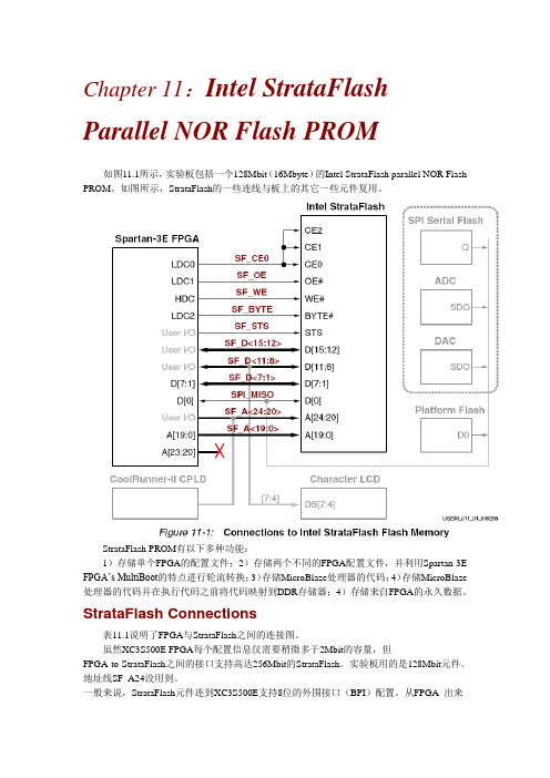
Chapter 11:Intel StrataFlash Parallel NOR Flash PROM如图11.1所示,实验板包括一个128Mbit(16Mbyte)的Intel StrataFlash parallel NOR Flash PROM。
如图所示,StrataFlash的一些连线与板上的其它一些元件复用。
StrataFlash PROM有以下多种功能:1)存储单个FPGA的配置文件;2)存储两个不同的FPGA配置文件,并利用Spartan-3E FPGA’s MultiBoot的特点进行轮流转换;3)存储MicroBlaze处理器的代码;4)存储MicroBlaze 处理器的代码并在执行代码之前将代码映射到DDR存储器;4)存储来自FPGA的永久数据。
StrataFlash Connections表11.1说明了FPGA与StrataFlash之间的连接图。
虽然XC3S500E FPGA每个配置信息仅需要稍微多于2Mbit的容量,但FPGA-to-StrataFlash之间的接口支持高达256Mbit的StrataFlash。
实验板用的是128Mbit元件。
地址线SF_A24没用到。
一般来说,StrataFlash元件连到XC3S500E支持8位的外围接口(BPI)配置。
从FPGA 出来的高4位并没有直接连到StrataFlash。
相反,在配置时由XC2C64 CPLD控制这些管脚。
正如表11.1所示,StrataFlash的一些连线与其它一些器件复用。
Shared Connections除了StrataFlash的一些连线与其它一些器件复用外,StrataFlash的一些存储空间也与其它器件复用。
Character LCD字符LCD采用4位的数据接口。
显示数据的连线同样与StrataFlash PROM上的信号线SF_D<11:8>复用。
如表11.2所示,FPGA通过SF_CE0和LCD_RW信号线来控制StrataFlash PROM的访问通道或字符LCD的读状态。
- 1、下载文档前请自行甄别文档内容的完整性,平台不提供额外的编辑、内容补充、找答案等附加服务。
- 2、"仅部分预览"的文档,不可在线预览部分如存在完整性等问题,可反馈申请退款(可完整预览的文档不适用该条件!)。
- 3、如文档侵犯您的权益,请联系客服反馈,我们会尽快为您处理(人工客服工作时间:9:00-18:30)。
Spartan-3E Starter Kit Board User GuideChapter 1: Introduction and OverviewChapter 2: Switches, Buttons, and KnobChapter 3: Clock SourcesChapter 4: FPGA Configuration OptionsChapter 5: Character LCD ScreenChapter 6: VGA Display PortChapter 7: RS-232 Serial PortsChapter 8: PS/2 Mouse/Keyboard PortChapter 9: Digital to Analog Converter (DAC)Chapter 10: Analog Capture CircuitChapter 11: Intel StrataFlash Parallel NOR Flash PROM Chapter 12: SPI Serial FlashChapter 13: DDR SDRAMChapter 14: 10/100 Ethernet Physical Layer Interface Chapter 15: Expansion ConnectorsChapter 16: XC2C64A CoolRunner-II CPLDChapter 17: DS2432 1-Wire SHA-1 EEPROMChapter 1:Introduction and OverviewSpartan-3E入门实验板使设计人员能够即时利用Spartan-3E系列的完整平台性能。
设备支持:Spartan-3E、CoolRunner-II关键特性:Xilinx 器件: Spartan-3E (50万门,XC3S500E-4FG320C), CoolRunner™-II (XC2C64A-5VQ44C)与Platform Flash(XCF04S-VO20C)时钟:50 MHz晶体时钟振荡器存储器: 128 Mbit 并行Flash, 16 Mbit SPI Flash, 64 MByte DDR SDRAM连接器与接口:以太网10/100 Phy, JTAG USB下载,两个9管脚RS-232串行端口, PS/2类型鼠标/键盘端口, 带按钮的旋转编码器, 四个滑动开关,八个单独的LED输出, 四个瞬时接触按钮, 100管脚hirose扩展连接端口与三个6管脚扩展连接器显示器: VGA显示端口,16 字符- 2 线式LCD电源:Linear Technologies 电源供电,TPS75003三路电源管理IC 市场:消费类, 电信/数据通信, 服务器, 存储器应用:可支持32位的RISC处理器,可以采用Xilinx的MicroBlaze 以及PicoBlaze嵌入式开发系统;支持DDR接口的应用;支持基于Ethernet网络的应用;支持大容量I/O扩展的应用。
Choose the Starter Kit Board for Your NeedsSpartan-3E FPGA Features and Embedded Processing FunctionsSpartan3-E FPGA 入门实验板具有Spartan3-E FPGA系列突出独特的特点和为嵌入式处理发展与应用提供了很大的方便。
该板的特点如下:Spartan3-E特有的特征:并行NOR Flash配置;通过并行NOR Flash PROM 实现FPGA 的多种配置方式嵌入式系统:MicroBlaze™ 32-bit 嵌入RISC处理器;PicoBlaze™ 8-bit 嵌入控制器;DDR 存储器接口Learning Xilinx FPGA, CPLD, and ISE Development SoftwareBasicsSpartan3-E FPGA 入门实验板比其他的入门实验板先进、复杂。
它是学习FPGA或CPLD 设计和怎样运用ISE软件的基础。
Advanced Spartan-3 Generation Development Boards入门实验板示范了MicroBlaze™ 32-bit 嵌入式处理器和EDK的基本运用。
其更先进的地方在于配了额外的外设和FPGA逻辑,包括SP-305入门实验板。
Key Components and Features主要特征:1)XC3S500E(Spartan-3e):多达232个用户I/O口;320个FPGA封装管脚;超过10000个逻辑单元。
2)4Mbit的Flash 配置PROM;3)64个宏单元的XC2C64A CoolRunner CPLD;4)64 MByte (512 Mbit) of DDR SDRAM, ×16 数据接口, 100+ MHz;5)16 MByte (128 Mbit) of 并行NOR Flash (Intel Strata Flash):FPGA配置存储;Micro Blaze代码存储/映射;6)16 Mbits of SPI serial Flash (STMicro):FPGA配置存储;Micro Blaze代码存储/映射;7)16字符-2线式LCD显示屏;8)PS/2鼠标或键盘接口;9)VGA显示接口;10)10/100以太PHY (要求FPGA内部具有以太MAC);11)2个9-管脚的RS-232端口(DTE和DCE两种类型);12)FPGA/CPLD下载/调试USB接口;13)50Hz时钟晶振;14)1线式的SHA-1位流复制保护串行EEPROM;15)Hirose FX2扩展连接口;16)3个管脚扩展连接器;17)4个SPI-DAC 转换器输出管脚;18)2个SPI带可编程增益ADC输入管脚;19)Chip Scope™软件调试接口;20)带按钮的旋转编码器;21)8个单独的LED输出;22)4个滑动开关;23)4个按钮开关;24)SMA时钟输入;25)8管脚插槽辅助晶振Design Trade-Offs(设计方案)Configuration Methods Galore!FPGA的一个典型应用就是使用单永久性存储器来存储配置信息。
为了说明新的Spartan-3E的性能,入门实验板有3个不同的配置存储源,这需要一起正确使用。
额外的配置功能使入门实验板比典型的Spartan-3E应用更复杂。
入门实验板包括JTAG可编程USB接口。
片上的线路简化了器件的编程过程。
在典型的应用中,JTAG编程硬件在片外或在一个单独的编程模块上,如XILINX USB电缆平台。
Voltages for all Applications入门实验板利用TI公司的TPS75003芯片(专门为Spartan-3E的FPGA提供电源)作为三态输出调整仪。
该调整仪适用多种FPGA的应用。
但是,入门实验板包括DDR SDRAM,这需要它自身快速的电流来供给。
简单地说,带USB接口的JTAG下载方式解决了需要单独配备1.8V电源的问题。
Chapter 2:Switches, Buttons, and KnobSlide SwitchesLocations and Labels入门实验板具有4个滑动开关,如图2.1所示。
Operation当开关关上或上拉时,FPGA的管脚连接3.3V电源,即逻辑高电平。
断开或下拉时,FPGA 管脚接地,逻辑低电平。
一般开关的机械闭合时间为2ms,这里没有使用活动的回弹线路,尽管这种线路可以很容易地加到FPGA上。
UCF Location Constraints图2.2为4个滑动开关提供了UCF约束、I/O口分配和I/O口标准。
这里没有用到上拉电阻。
但是,当开关处于中间转换位置时,它被定义为输入。
Push-Button SwitchesLocations and Labels入门实验板有4个瞬时按钮开关,如图2.3所示。
BTN_NORTH、BTN_EAST、BTN_SOUTH、and BTN_WEST。
注:a 所有的BTN_*按钮输入需要内部的下拉电阻;b 在一些FPGA应用中BTN_SOUTH作为软复位使用。
Operation按下按钮,FPGA接到3.3v电源,如图2.4。
没有按下时,鉴于内部下拉电阻的原因,FPGA 管脚产生一个逻辑低电平。
图2.5说明了怎样去定义下拉电阻的UCF。
这里按钮上没有活动的回弹线路。
在一些应用中,BTN_SOUTH按钮开关充FPGA选择复位功能的软复位。
UCF Location Constraints图2.5为4个按钮开关提供了UCF约束、I/O口分配和I/O口标准。
并为每个输入管脚定义下拉电阻。
Rotary Push-Button SwitchLocations and Labels如图2.3所示,旋转按钮处4个分开的按钮的中间。
该开发产生3个输出:2个轴状编码输出ROT_A和ROT_B。
中心的按钮是ROT_CENTER。
Operation旋转按钮有2个不同的功能。
只要轴柄一转,按钮就旋转并输出值。
该轴也可以按下,和按钮开关一样。
Push-Button Switch按下握柄或按钮,则FPGA接通3.3V,如图2.6所示。
使用内部的下拉电阻产生低电平。
图2.9说明了怎样去定义UCF的下拉电阻。
这里按钮上没有活动的回弹线路。
Rotary Shaft Encoder首先,旋转编码更像是个连接到中心的凸轮。
旋转轴柄可操作两个按钮开关,如图2.7所示。
选择一个开关连接地,产生低电平。
当开关开时,FGPA内部的上拉电阻将该信号拉为高电平。
图2.9是对其UCF约束的描述,怎样去定义上拉电阻。
FPGA电路很方便地译码A和B的输入信号,但考虑到开关的机械特性,转换时会产生输入噪音。
如图2.8所示,噪音错误地报告额外的旋转事件或甚至报告旋转相反的方向。
UCF Location ConstraintsDiscrete LEDsLocations and Labels入门实验板在滑动开关的上面有8个独立的贴片LED。
OperationLED一端接地,另一端通过390欧的限流电阻接到Spartan-3E上。
要点亮一个LED,向相应的控制位置高。
UCF Location ConstraintsChapter 3: Clock SourcesOverview图3.1所示,入门实验板支持3个主时钟输入源。
1)包括一个50MHz的时钟晶振2) 通过SMA连接器,时钟可以板外供应。
反之,FPGA也可以提供时钟信号或其它高速信号给SMA连接器3)分列式8-DIP时钟晶振插槽Clock Connections每个时钟的输入直接连到Bank0的输入全局缓冲I/O。