ch-17 UPS电源
伊顿 9PX 锂电 UPS 1000VA-3000VA 说明书

伊顿 9PX 锂电 UPS1000VA-3000VA高级保护:• 边缘计算• 中小型数据中心• IT 、网络、存储和电信•基础设施、工业和医疗9PX 锂电 UPS在线双转换锂电 UPS更长的使用寿命•与铅酸电池通常 3-5 年的使用寿命相比,9PX 锂电 UPS 的电池使用寿命延长至 8-10 年。
•锂电 UPS 消除了传统铅酸电池 UPS 更换电池的需求以及由此产生的用户成本(规划、人工、运输)。
•锂电 UPS 可获得包括 UPS 电子组件、内部电池和 EBM 在内的五年工厂保修的服务支持。
管理和网络安全•伊顿千兆网络管理卡提供双重网络安全认证(UL 2900-1 和 IEC 62443-4-2)。
•伊顿的 IPM 电源管理软件可与领先的虚拟化环境和云服务工作流工具无缝集成。
•9PX 锂电 UPS 可以直接测量每个插座组的能耗。
用电量可以通过液晶显示屏或伊顿的 IPM 电源管理软件实时监控。
•负载分段控制功能允许在电池模式下优先关闭非必要设备,以最大限度提高关键设备的运行时间。
高性能•双转换拓扑。
伊顿 9PX 锂电 UPS 可持续监控电源状况并调节电压和频率。
•通过“能源之星”认证的 9PX 锂电 UPS 可提供最高的能效等级,从而降低 UPS 的电力消耗和机房的制冷成本。
•UPS 的内置旁路允许在发生内部故障时保持运行连续性,提供维护旁路的选配件以方便进行 UPS 的在线更换和维护。
•最多可使用 4 个支持即插即用的外部电池模块,以延长运行时间。
如有必要,可持续运行系统数小时。
易于安装和升级•更轻的重量:与传统铅酸电池 UPS 相比,9PX 锂电 UPS 重量减少了多达 20%,电池箱重量减少了 40% 以上。
•更小的尺寸:电池箱尺寸已减少到 1U ,为 IT 设备节省了更多的空间。
• 固件升级可以通过千兆网络管理卡在本地或远程完成。
•所有产品型号均随附塔式或机架式安装所需的套件。
伊顿 9PX 锂电 UPS 技术规格伊顿 9PX 3000VA213541图形液晶显示屏:-清晰显示有关 UPS 状态和测量值的信息-增强的配置功能2 管理卡的插槽(Netpack 型号随附网络卡作为标配)3 输出:8 x IEC 10A + 2 x IEC 16A ,带电能计量功能(包括 2 个可编程组)4U SB 端口,1 个串行端口,远程开/关,远程电源关闭和继电器输出5 外部电池 (EBM)连接器技术规格2021年06月 PA153013EN/pq 热线电话:400 889 3938上海上海市长宁区临虹路280弄3号电话:+86 (21) 5200 0099传真:+86 (21) 5200 0300邮编:200335深圳深圳市宝安72区宝石路8号电话:+86 (755) 2757 2666传真:+86 (755) 2757 2730邮编:518101西安西安市高新区锦业路86号电话:+86 (29) 8824 1826传真:+86 (29) 8824 1362邮编:710077北京北京市朝阳区建国门外大街8号国际财源中心(IFC 大厦)9层电话:+86 (10) 5925 9200传真:+86 (10) 5925 9211 邮编:100022广州广州市天河区冼村路11号之二保利威座北塔第13层05-07室 电话:+86 (20) 3585 9666传真:+86 (20) 3821 0986邮编:510623成都成都市锦江区创意产业商务区三色路38号博瑞-创意成都写字楼A 座1003-1004室电话:+86 (28) 8621 1886 传真:+86 (28) 8621 2009邮编:610063沈阳沈阳市和平区和平北大街69号总统大厦C 座2107室电话:+86 (24) 2281 5649 传真:+86 (24) 2281 5644邮编:110003Eaton Power Quality (Shanghai) Co., Ltd.武汉武汉市昙华林路202号泛悦中心A 座1008室手机:+86133****9867+86138****2255传真:+86 (27) 8771 1958邮编:430070。
电力系统单线图

1AP15 1AXH1-1 外延车间 办公楼1F
1AAER 4APE1 消防泵房
1AP22 品保实验 室 1AA1 空调机房
AH10预留柜
12AT5
12AT2-4
1AW1 纯水 1AAR 楼顶动力 1AA2 外延空调 1AP11 测量间 烤盘炉
电容补偿装置
备用
AH9预留柜AH7出线柜 AH5避雷柜
AH3计量柜
AH1高压进线柜
若水1#高压进1AT1
11AT2-4
11AT5
11AT6
11AT7
11AT8
11AT9
11AT10
11AT11
电容补偿装置
UPS-D 1AP13 1AP5 1AP17 1AP3 备用 特气纯化 外延车间 镀膜车间 外延车间 镀膜车间 器 1AAH1-1 1AP21 OAL 1AG1 1AG2 1AP8 1AP4 办公楼空 原玄照车 真空泵 动力机房 动力房 成测车间 镀膜车间 调 间 芯片新增 1ALH1-1 3AP1 1AP12 1AP7 RCU(走 车间照明 废水站 外延车间 成测车间 道) 4APH1 1AA3 CH-1 品保实验 芯片空调 1#冰机 室 1AG4 锅炉房
12AT7
12AT6
SAL-1 配电房空 调 双电源柜 厂务办公 室 1APEH1-1 应急照明 1AGE1 PCW
备用
备用 1EATS 常用电源 备用
1AP14 1ALH1-3 外延车间 办公楼3F CH-2 2#冰机 1AP16 外延车间
备用
1ALH1-1
1AP1 1AAER 清洗车间 楼顶消防 备用 1AG3 动力机房
1EAT ATS备用 电源 1AP10 测量间 烤盘炉
1AP2 光刻车间 1AP6 切割研磨 车间
施耐德 BK650M2-CH APCBack UPS 不间断电源(UPS) 数据表
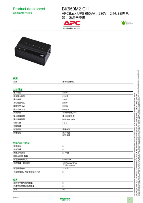
Product data sheetCharacteristicsBK650M2-CHAPCBack UPS 650VA,230V,2个USB充电器,适用于中国概要交期通常现货供应主要信息输入电压230 V 其他输入电压220 伏输出电压230 V 其它输出电压230 V 额定功率 [W]390 W 额定功率 [VA]650 VA 产品类型不间断电源(UPS)输入连接类型澳大利亚/中国输出连接类型4chinese outlet 电缆长度1.5 M 电缆数量1电池类型铅酸电池附带设备用户手册USB电缆电池与运行时间预装电池空电池槽典型充电时间24 小时RBC™ 数量1电池充电电压(瓦)5 W rated电池容量(伏安时)124 VAh runtime 0 VAh runtime电池使用寿命3…5 年可自动检测、可扩展的延时时间通用空闲功率模块插槽数量已填充功率模块插槽数量冗余NoT h e i n f o r m a t i o n p r o v i d e d i n t h i s d o c u m e n t a t i o n c o n t a i n s g e n e r a l d e s c r i p t i o n s a n d /o r t e c h n i c a l c h a r a c t e r i s t i c s o f t h e p e r f o r m a n c e o f t h e p r o d u c t s c o n t a i n e d h e r e i n .T h i s d o c u m e n t a t i o n i s n o t i n t e n d e d a s a s u b s t i t u t e f o r a n d i s n o t t o b e u s e d f o r d e t e r m i n i n g s u i t a b i l i t y o r r e l i a b i l i t y o f t h e s e p r o d u c t s f o r s p e c i f i c u s e r a p p l i c a t i o n s .I t i s t h e d u t y o f a n y s u c h u s e r o r i n t e g r a t o r t o p e r f o r m t h e a p p r o p r i a t e a n d c o m p l e t e r i s k a n a l y s i s , e v a l u a t i o n a n d t e s t i n g o f t h e p r o d u c t s w i t h r e s p e c t t o t h e r e l e v a n t s p e c i f i c a p p l i c a t i o n o r u s e t h e r e o f .N e i t h e r S c h n e i d e r E l e c t r i c I n d u s t r i e s S A S n o r a n y o f i t s a f f i l i a t e s o r s u b s i d i a r i e s s h a l l b e r e s p o n s i b l e o r l i a b l e f o r m i s u s e o f t h e i n f o r m a t i o n c o n t a i n e d h e r e i n .高度10.5 Cm宽度28.6 Cm深度17.1 Cm净重 3.2 Kg安装偏好No preference安装类型Not rack-mountable可安装在双柱上0USB 兼容No输入网络频率45...65 Hz插头标准澳大利亚/中国输入电压限制160...278 V输出最大可配置功率(瓦)390 W拓朴备用波形类型正弦波逐步逼近最大可配置功率(伏安)650 VA转换时间一般 0.6 秒:最多 1 秒相符性符合标准EN/IEC 62040-1:2019/A11:2021EN/IEC 62040-2:2006/AC:2006EN/IEC 62040-2:2018环境运行温度0…40 °C相对湿度10…90 %工作海拔0...3000 ft贮存环境温度-15…45 °C存储相对湿度5…95 %存储高度0.0000000000…4572.0000000000 M声响级别40 dBA通讯与管理控制面板LED status display with on line : on battery : replace battery and overload indicators 警报Alarm when on battery : distinctive low battery alarm : overload continuous tone alarm浪涌保护及滤波浪涌抑制能量310 J包装单位Unit Type of Package 1PCENumber of Units in Package 11Package 1 Height24.1 CmPackage 1 Width14.2 CmPackage 1 Length32.2 CmPackage 1 Weight 3.5 Kg产品类型Green Premium 产品REACh法规REACh 声明欧盟ROHS指令符合欧盟ROHS声明无汞是中国 ROHS 管理办法中国 ROHS 声明RoHS 豁免信息是环境披露产品环境文件流通资料产品使用寿命终期信息WEEE该产品必须经特定废物回收处理后弃置于欧盟市场,绝不可丢弃于垃圾桶中。
UPS 基本概念
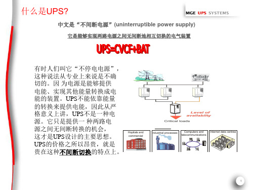
Non-sensitive loads Rectifier/ charger Battery
Inverter
UPS
Normal utility power (disturbances and system tolerances)
Static bypass
Maintenance bypass
10
UPS的电压变换作用
输入
电压变换
380V
输出
220V 380V 400V 415V
(稳压作用)
11
UPS的频率变换作用
输入
频率变换
50Hz
输出 50Hz (稳频作用) 60Hz 400Hz
12
UPS的后备功能
交流输入
整流器
负载
逆变器
电池
UPS带有电池,贮存一定的能量,一方面在电网停电或发生间断时继续供电一段
Information Technology(信息系统) 数据 应用程序 操作系统 服务器 网络设备等
Environment(环境) NCPI
NCPI—பைடு நூலகம்etwork Critical Physical Infrastructure,即网络关键基础物理设施。
NCPI包含3个子系统: • 电力供应子系统 • 空调调节子系统 • IT设备机械支撑子系统
概率值或日累计超过不超过 72
min,且每30min中超标不超 过
5min;
(3)对测量方法和测量仪器作 出
基本规定; (4)提供不平衡度算法。
对测量仪器提出了基本要求
4
电网存在的质量问题:
5
6
UPS在信息系统中的位置
伊顿(EATON) 9SX 15-20KPM(CH)系列在线式UPS说明书

Eaton 9SX 15-20KPM(CH)系列在线式UPS2019伊顿(EATON)公司保留所有权利本手册内所包含的所有内容属于伊顿所有,未经许可,不得复制(或摘录)。
我们已经尽一切努力确保手册内信息的正确性,但出现错误或遗漏是难免的,对此我们不负任何责任,并保留对设计进行修改的权利。
操作安全1. 在使用本产品前,请仔细阅读“安全注意事项”,以确保正确和安全的使用。
并请妥善保存此手册。
2. 操作时,请注意所有警示标记,并按要求进行操作。
3. 避免在阳光直接照射、雨淋或在潮湿的环境使用本设备。
4. 请勿安装在靠近热源区域,或有电暖炉、热炉等类似设备的附近。
5. 放置UPS时,在其四周要保留安全距离,保证通风。
安装时,请参照此手册。
6. 清洁时,请使用干燥的物品进行擦拭。
7. 若遇火警,请正确使用干粉灭火器进行灭火。
勿使用液体灭火器,以免触电。
电气安全1. 上电前,请确认已正确接地,并检查所有接线和电池极性的连接正确。
2. 当UPS需要移动或重新接线时,应将交流输入电源断开,并保证UPS完全关机,否则输出端仍可能带电,有触电的危险。
3. 请使用本公司指定的附加装置和附件。
4. 为了符合EMC的要求,UPS的输出线长度应在10米以内。
电池安全1. 电池的寿命随环境温度的升高而缩短,定期更换电池可保证UPS工作正常,并保证足够的后备时间。
2. 蓄电池的维护必须由具备蓄电池专业知识的人员来进行。
3. 更换蓄电池,其类型、型号与数量均应与原电池保持一致。
4. 蓄电池存在电击危险和短路电流危险,为避免触电伤人事故,在更换电池时,请遵守下列警告:A. 请勿佩带手表、戒指或类似金属物体;B. 使用绝缘的工具;C. 穿戴橡胶鞋和绝缘手套;D. 请勿将金属工具或类似的金属零件放在电池上;E. 在拆电池连接端子前,必须先断开连接在电池上的负载。
5. 请勿将蓄电池暴露于火中,以免引起爆炸,危及人身安全。
6. 非专业人士请勿打开或损毁蓄电池,因为电池中的电解液含有强酸等危险物质,会对皮肤和眼睛造成伤害。
设备编号规则

设备编号规则目录1.概述 (3)2.需编号的内容 (3)2.1.电气类 (3)2.2.暖通类 (3)2.3.弱电类 (3)2.4.消防类 (4)3.编号原则 (4)3.1.编号在设备图形中位置 (4)3.2.块属性的编辑方法(以生成精密空调块为示例) (4)3.2.1.新建CAD文件 (4)3.2.2.画好块的图形 (4)3.2.3.编辑设备名称及容量等信息 (5)3.2.4.编辑块属性 (5)3.3.代码编辑原则 (8)3.3.1.设备编号的组成 (8)3.3.2.各部分的具体含义 (9)4.编号示例 (11)4.1.电气设备编号 (11)4.2.暖通设备编号 (11)4.3.弱电设备编号 (11)4.4.消防设备编号 (11)1.概述为方便各专业绘制图纸,各专业之间相互配合以及提高图纸的可读性,制定本设备编号规则。
设备编号由各专业编辑后汇总到装修图纸中,在相应的平面图中应能表示出所有设备及其编号。
在所有项目的初步设计及后期的过程中都要按照本规则进行编号。
2.需编号的内容2.1.电气类需编号的电气类设备主要包含以下2类:1、配电柜(箱)、控制柜(箱):各种电压等级的市电配电柜(箱)、发电机输出柜(箱)、UPS配电柜(箱)、列头柜、空调配电柜(箱)、照明配电箱、应急照明配电箱、风机控制箱等。
2、所有电气设备:变压器、柴油发电机、UPS、直流电源等设备。
2.2.暖通类需编号的暖通类设备主要包含以下2类:1、空调系统设备:精密空调、各种制冷机、室外机、冷却塔、水泵、板式换热器等。
2、通风系统:新风机、排气风机、排烟风机等。
2.3.弱电类需编号的弱电类设备主要包含以下3类:1、综合布线类:所有机柜、机柜列、网络列头柜(箱)。
2、安防类:门禁、摄像头、防盗报警。
3、环境监控类:温湿度传感器、漏水报警、各种转换模块。
2.4.消防类需编号的消防类设备主要包含以下2类:1、气体灭火类:钢瓶。
2、报警类:报警主机、启动控制器、感烟探测器、感温探测器、极早期控制主机。
UPS分区表
二字代码
IL IT CI KZ KE KG LV LR CH LT LU MK MG ML MT MR MD MA NL NE NG NO PL PT RE RO RU RW SN SC SL SK ES SE CH TJ TZ TG TN TR TM UG UA UZ CS ZR
区域代码
CGN CGN CGN CGN CGN CGN CGN CGN CGN CGN CGN CGN CGN CGN CGN CGN CGN CGN CGN CGN CGN CGN CGN CGN CGN CGN CGN CGN CGN CGN CGN CGN CGN CGN CGN CGN CGN CGN CGN CGN CGN CGN CGN CGN CGN CGN
46
IRELAND REP.
爱尔兰
IE
CGN
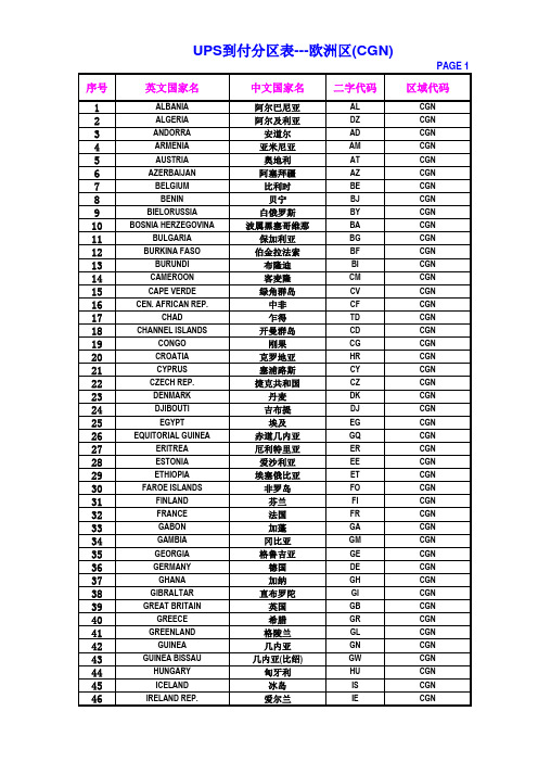
UPS到付分区表---欧洲区(CGN)
PAGE 2
序号 47 48 49 50 51 52 53 54 55 56 57 58 59 60 61 62 63 64 65 66 67 68 69 70 71 72 73 74 75 76 77 78 79 80 81 82 83 84 85 86 87 88 89 90 91 92
中文国家名
阿尔巴尼亚 阿尔及利亚 安道尔 亚米尼亚 奥地利 阿塞拜疆 比利时 贝宁 白俄罗斯 波属黑塞哥维那 保加利亚 伯金拉法索 布隆迪 客麦隆 绿角群岛 中非 乍得 开曼群岛 刚果 克罗地亚 塞浦路斯 捷克共和国 丹麦 吉布提 埃及 赤道几内亚 厄利特里亚 爱沙利亚 埃塞俄比亚 非罗岛 芬兰 法国 加蓬 冈比亚 格鲁吉亚 德国 加纳 直布罗陀 英国 希腊 格陵兰 几内亚 几内亚(比绍) 匈牙利 冰岛
英文国家名
IEC62040-2-2005不间断电源系统(UPS)(可编辑)

IEC 62040-2-2005 不间断电源系统(UPS)NORME CEIINTERNATIONALEIEC62040-2INTERNATIONALDeuxième éditionSTANDARDSecond edition2005-10Alimentations sans interruption ASI ?Partie 2:Exigences pour la compatibilitéélectromagnétique CEMUninterruptible power systems UPS ?Part 2:Electromagnetic compatibility EMCrequirementsIEC 2005 Droits de reproduction réservés Copyright - all rights reservedAucune partie de cette publication ne peut être reproduite ni No part of this publication may be reproduced or utilized in any utilisée sous quelque forme que ce soit et par aucun procédé, form or by any means, electronic or mechanical, includingélectronique ou mécanique, y compris la photocopie et les photocopying and microfilm, without permission in writing frommicrofilms, sans l'accord écrit de l'éditeur. the publisherInternational Electrotechnical Commission, 3, rue de Varembé, PO Box 131, CH-1211 Geneva 20, SwitzerlandTelephone: +41 22 919 02 11 Telefax: +41 22 919 03 00 E-mail: ****************://0>.CODE PRIXWPRICE CODECommission Electrotechnique InternationaleInternational Electrotechnical CommissionМеждународнаяЭлектротехническаяКомиссияPour prix, voir catalogue en vigueurFor price, see current catalogue//. ? 1 ?INTERNATIONAL ELECTROTECHNICAL COMMISSIONUNINTERRUPTIBLE POWER SYSTEMS UPS ?Part 2: Electromagnetic compatibility EMC requirementsFOREWORD1 The International Electrotechnical Commission IEC is a worldwide organization for standardization comprisingall national electrotechnical committees IEC National Committees. The object of IEC is to promoteinternational co-operation on all questions concerning standardization in the electrical and electronic fields. Tothis end and in addition to other activities, IEC publishes International Standards, Technical Specifications,Technical Reports, Publicly Available Specifications PAS and Guides hereafter referred to as “IECPublications”. Their preparation is entrusted to technical committees; any IEC National Committee interestedin the subject dealt with may participate in this preparatory work. International, governmental and non-governmental organizations liaising with the IEC also participate in this preparation. IEC collaborates closelywith the International Organization for Standardization ISO in accordance with conditions determined byagreement between the two organizations2 The formal decisions or agreements of IEC on technical matters express, as nearly as possible, an internationalconsensus of opinion on the relevant subjects since each technical committee has representation from allinterested IEC National Committees3 IEC Publications have the form of recommendations for international use and are accepted by IEC NationalCommittees in that sense. While all reasonable efforts are made to ensure that the technical content of IECPublications is accurate, IEC cannot be held responsible for the way in which they are used or for anymisinterpretation by any end user4 In order to promote internationaluniformity, IEC National Committees undertake to apply IEC Publications transparently to the imum extent possible in their national and regional publications. Any divergencebetween any IEC Publication and the corresponding national or regional publication shall be clearly indicated inthe latter5 IEC provides no marking procedure to indicate its approval and cannot be rendered responsible for anyequipment declared to be in conformity with an IEC Publication6 All users should ensure that they have the latest edition of this publication7 No liability shall attach to IEC or its directors, employees, servants or agents including individual experts andmembers of its technical committees and IEC National Committees for any personal injury, property damage orother damage of any nature whatsoever, whether direct or indirect, or for costs including legal fees andexpenses arising out of the publication, use of, or reliance upon, this IEC Publication or any other IECPublications8 Attention is drawn to the Normative references cited in this publication. Use of the referenced publications isindispensable for the correct application of this publication9 Attention is drawn to the possibility that some of the elements of this IEC Publication may be the subject ofpatent rights. IEC shall not be held responsible for identifying any or all such patent rightsInternational Standard IEC 62040-2 has beenprepared by subcommittee 22H: UninterruptiblePower Systems UPS, of IEC technical committee 22: Power electronic systems andequipmentThis second edition cancels and replaces the first edition published in 1999 and constitutes atechnical revisionThis edition includes the following significant technical changes with respect to the previousedition:a New UPS categories C1, C2, C3 replace previous “restricted and unrestricted salesdistribution” emission only related UPS categories “A, B and Table 2”. C1, C2, C3 take intoaccount both emission and immunity requirements of the environment in which the UPS isintended to //. ? 2 ?b Mains terminal and a.c. output interference voltage limits apply now for UPS with currentsin excess of 400 A. They are identical to those applying to UPS with currents in excess of100 Ac Lower a.c output interference voltage limits apply now for UPS with currents in excess of100 Ad Higher immunity requirements apply now for UPS intended to operate in commercial andindustrial environmentsThe text of this standard is based on the following documents:FDIS Report on voting22H/74A/FDIS 22H/82/RVDFull information on the voting for the approval of this standard can be found in the report onvoting indicated in the above tableIEC 62040 consists of the following parts, under the general title Uninterruptible power systems UPS:Part 1-1: General and safety requirements for UPS used in operator access areasPart 1-2: General and safety requirements for UPS used in restricted access locationsPart 2: Electromagnetic compatibility EMC requirementsPart 3: Method of specifying the performance and test requirementsThe committee has decided that the contents of this publication will remain unchanged until themaintenance result date indicated on the IEC web site under "////. in the datarelated to the specific publication. At this date, the publication will be? reconfirmed; withdrawn; replaced by a revised edition, or amended //. ? 3 ?CONTENTS1 Scope..62 Normative references73 Terms and definitions83.1 83.2 84 Environment.85 UPS Categories..85.1 UPS of category C1..85.2 UPS of category C2..95.3 UPS of category C3..95.4 UPS of category C4..95.5 Categories and environment..96 Emission..106.1 General.106.2 General requirements.106.3 General measurement conditions.106.4 Conducted emissions.116.5 Radiated emissions.137 Immunity..147.1 General.147.2 General requirements and performance criteria.147.3 Basic immunity requirements ? High-frequency disturbances..157.4 Immunity to low-frequency signals177.5 Immunity to power-frequency magnetic field177.6 Immunity to voltage dips, short interruptions and voltage variations.17Annex A normative Electromagnetic emission ? Test methods..18A.1 General.18A.2 Measuring equipment.18A.3 Test unit configuration19A.4 Determination of imum emission configurations..20A.5 Operation of the equipment under test21A.6 Method of measurement of mains terminal interference voltage.21A.7 Method of measurement at a.c. output ports where applicable.23A.8 Method of measurement of radiated emission.23A.9 Measurement site.24A.10 Equipment set-up for radiated emission tests..24A.11 Measurement of radiated magnetic disturbances..25Annex B informative Electromagnetic emission limits and measurement methods ofmagnetic field ? H field..33Annex C informative Electromagnetic emission ? Limits of signal ports.35Annex D normative Electromagnetic immunity ? Test methods..36D.1General.36D.2Electrostatic discharge ESD.36D.3Immunity to radiated electromagnetic EM fields..36D.6Immunity to low-frequency signals37Annex E informative User installation testing..39//. ? 4 ?Annex ZZ informative Coverage of Essential Requirements of EC Directives40Figure 1 ? Examples of ports.8Figure A.1 ? Circuit for disturbance voltage measurements on mains supply or UPSoutput26Figure A.2 ? Minimum alternative test site26Figure A.3 ? Set-up for measurement of conducted emission for table-top units.27Figure A.4 ? Test set-up for floor-standing units.27Figure A.5 ? Test configuration for table-top equipment conducted emissionmeasurement28Figure A.6 ? Test configuration for table-top equipment conducted emissionmeasurement ? Plan view..29Figure A.7 ? Alternative test configuration for table-top equipment conductedemission measurement ? Plan view29//. ? 5 ?Figure A.8 ? Test configuration for floor-standing equipment conducted emissionmeasurement30Figure A.9 ? Test configuration for table-top equipment radiated emissionrequirement..31Figure A.10 ? Test configuration for floor-standing equipment radiated emissionmeasurement32Figure B.1 ? Test set-up for measuring radiated disturbances.33Figure D.2 ? Phase unbalance38Table 1 ? Limits of mains terminal interference voltage frequency range 0,15 MHz to30 MHz for category C1 UPS and category C2 UPS equipment..12Table 2 ? Limits of mains terminal interference voltage frequency range 0,15 MHz to30 MHz for Category C3 UPS equipment..12Table 3 ? Limits of radiated emission in the frequency range 30 MHz to 1 000 MHz.13Table 4 ? Performance criteria for immunity tests.14Table 5 ? Minimum immunity requirements for UPS intended for UPS of category C1..15Table 6 ? Minimum immunity requirements for UPS of category C2 and C3.16Table B.1 ? UPS which has a rated output current less than, or equal to, 16 A34Table B.2 ? UPS which has a rated output current greater than 16A.34 Table C.1 ? Limits of signal ports..35//. ? 6 ?UNINTERRUPTIBLE POWER SYSTEMS UPS ?Part 2: Electromagnetic compatibility EMC requirements1 ScopeThis part of IEC 62040 applies to UPS units intended to be installed as a unit or in UPS systems comprising a number of interconnected UPS and associatedcontrol/switchgear forming a single power system; and? in anyoperator accessible area or in separated electrical locations, connected to low-voltage supply networks for either industrial or residential, commercial and light industrialenvironments.This part of IEC 62040 is intended as a product standard allowing the EMC conformityassessment of products of categories C1, C2 and C3 as defined in this part of IEC 62040,before placing them on the marketEquipment of category 4 is treated as a fixed installation. Checking is generally done after installation in its final place of use. Sometimes partial checking may be done before. SeeAnnex EThe requirements have been selected so as to ensure an adequate level of electromagneticcompatibility EMC for UPS at public and industrial locations. These levels cannot, however,cover extreme cases, which may occur in any location but with extremely low probability ofoccurrence.This part of IEC 62040 takes into account the differing test conditions necessary toencompass the range of physical sizes and power ratings of UPSA UPS unit or system shall meet the relevant requirements of this part of IEC62040 as astand-alone product. EMC phenomena produced by any customers' load connected to theoutput of the UPS equipment shall not be taken into accountSpecial installation environments are not covered, nor are fault conditions of UPS taken intoaccountThis part of IEC 62040 does not cover d.c. supplied electronic ballast or UPS based onrotating machinesThis part of IEC 62040 states:EMC requirements;test methods;minimum performance //. 72 Normative referencesThe following referenced documents are indispensable for the application of this documentFor dated references, only the edition cited applies. For undated references, the latest editionof the referenced document including any amendments appliesIEC 60050-161:1990, International Electrotechnical Vocabulary IEV ? Chapter 161:Electromagnetic compatibilityIEC 61000-2-2:2002, Electromagnetic compatibility EMC ? Part 2-2: Environment ?Compatibility levels for low-frequency conducted disturbances and signalling in public low-voltage power supply systemsIEC 61000-3-2:2000, Electromagneticcompatibility EMC ? Part 3-2: LimitsLimits forharmonic current emissions equipment input current 16 A per phase IEC 61000-4-1:2000, Electromagnetic compatibility EMC ? Part 4-1: Testing and measure-ment techniquesOverview of IEC 61000-4 seriesIEC 61000-4-2:1995, Electromagnetic compatibility EMCPart 4-2: Testing andmeasurement techniques ? Electrostatic discharge immunity testIEC 61000-4-3:2002, Electromagnetic compatibility EMCPart 4-3: Testing and measure-ment techniques Radiated, radio-frequency, electromagnetic field immunity testIEC 61000-4-4:2004, Electromagnetic compatibility EMC ? Part 4-4: Testing andmeasurement techniquesElectrical fast transient/burst immunity test IEC 61000-4-5:1995, Electromagnetic compatibility EMC ? Part 4-5: Testing and measure-ment techniques ? Surge immunity testIEC 61000-4-6:2003, Electromagnetic compatibility EMC ? Part 4-6: Testing and measure-ment techniques ? Immunity to conducted disturbances induced by radio-frequency fieldsIEC 61000-4-8:1993, Electromagnetic compatibility EMC ? Part 4-8: Testing and measure-ment techniques ? Power frequency magnetic field immunity testIEC 62040-3:1999, Uninterruptible power systems UPS ? Part 3: Method of specifying theperformance and test requirementsCISPR 16-1-1:2003, Specification for radio disturbance and immunity measuring apparatusand methods ? Part 1-1: Radio disturbance and immunity measuring apparatusMeasuringapparatusCISPR 16-1-2:2003, Specification for radio disturbance and immunity measuring apparatusand methods ? Part 1-2: Radio disturbance and immunity measuring apparatusAncillaryequipment ? Conducted disturbancesCISPR 22:2005, Information technology equipment ? Radio disturbance characteristics ?Limits and methods of measurement//. ? 8 ?3 Terms and definitionsFor the purposes of this document, the terms and definitions given in IEC 60050-161 relatedto EMC and to relevant phenomena apply, together with the following3.1 portparticular interface of the UPS with the external electromagnetic environment see Figure 13.2enclosure portphysical boundary of the UPS through which electromagnetic fields may radiate or impingeEnclosure portAC output power portAC input power portUPSSignal/control portEarth portDC power port batteryIEC1655/05Figure 1 ? Examples of ports4 EnvironmentThe following examples of environment cover the majority of UPS installations.a First environment: environment that includes residential, commercial and light industrialpremises directly connected without intermediate transformers to a public low-voltagemains supplyb Second environment: environment that includes all commercial, light industry andindustrial establishments other than those directly connected to a low-voltage mains thatsupplies buildings used for residential purposes5 UPS Categories5.1 UPS of category C1This category includes UPS intended for use without any restriction in the first environmentSuch UPS are suitable for use in residential establishmentsCategory C1 UPS shall meet the category C1 UPS emission limits and withstand theimmunity requirements of Table 5.//. ? 9 ?5.2 UPS of category C2This category includes UPS with an output current not exceeding 16 A and intended for usewithout any restriction in the second environment. Such UPS may also be used in the firstenvironment when connected:through industrial plugs and sockets or? through national plugs and sockets orpermanentlyCategory C2 UPS shall meet the category C2 UPS emission limits and withstand theimmunity requirements of Table 6The following wording shall be included in the instructions for useWARNING: This is a category C2 UPS product. In a residential environment, this productmay cause radio interference, in which case the user may be required to take additionalmeasures.5.3 UPS of category C3This category includes UPS with an output current exceeding 16 A and intended for use inthe second environment. Such UPS are suitable for use in commercialor industrialinstallations having a minimum boundary of 30 m from other buildings classified as firstenvironment.Category C3 UPS shall meet category C3- UPS emission limits and withstand the immunityrequirements of Table 6The following wording shall be included in the instructions for useWARNING: This is a product for commercial and industrial application in the secondenvironment installation restrictions or additional measures may be needed to preventdisturbances.5.4 UPS of category C4This category includes UPS intended for use in complex environments and subject to anagreement between supplier and customer regarding applicable emission and immunitylevels.The UPS of category C4 is not limited by current ratings5.5 Categories and environmentIf the environment has been determined as the first environment, UPS of category C1 or C2should be usedIf the environment has been determined as the second environment, UPS of category C2 orC3 should be usedIf the environment is not covered exclusively eitherby the first or second environment, UPS of category C4 should be //. ? 10 ?6。
- 1、下载文档前请自行甄别文档内容的完整性,平台不提供额外的编辑、内容补充、找答案等附加服务。
- 2、"仅部分预览"的文档,不可在线预览部分如存在完整性等问题,可反馈申请退款(可完整预览的文档不适用该条件!)。
- 3、如文档侵犯您的权益,请联系客服反馈,我们会尽快为您处理(人工客服工作时间:9:00-18:30)。
D. 输入/输出特性:
输入:额定电压 380V-25%-+15%,三相四线+PE,频率 50Hz±10,输入功率因数>0.99, 输入 THDi<5%
输出:电压 380V,50Hz±1%;稳压精度≤1%(0-100%负载),过载能力 110%,正常运行; 125%,60s;150%,1 分钟。输出功率因数 20KVA,0.8;40KVA,0.9;60KVA,0.95。
E. 浪涌保护器
1. 电涌保护器须符合并按 IEC61643 之规定进行定型试验和符合下列要求。
PA1610004-D-013
无锡万豪度假村酒店项目
CH17/P3
2017.03.15
无锡万豪度假村酒店项目 弱电系统 - 技术规格说明书
类型
氧化锌型式
额定电压
230/400V
最大工作电压
275V
允许内部短路电流
第四节 施工
17.4.1 安装应符合国家规定“电气装置工程施工及验收规范及国家颁发的有关规范及规定”。
第五节 调试
17.5.1 调前的准备工作
A. 检查设备安装位置及容量是否与设计图纸一致。
B. 检查设备功能是否正常。
17.5.2 系统调试
在各项设备单体调试完毕﹐进行系统调试。调试前应按照施工图对每台设备(进行编 号) 。
4) 逆变器必须装有故障敏感器、静态遮断器和输出断路器使关键负载自逆变器输出 切离而不致超过本规范规定之限度。
C. 系统旁路开关
1) 系统的机械旁路开关
UPS 须装置外部的机械旁路开关藉以手动旁路整个 UPS﹐以进行维修和运行。负 载转换至旁路电源及自旁路电源转回须由“先通后断”的顺序转换以使转换中对 负载之干扰不超过本规范之规定。
B. 后备电池为在线 1 小时。
C. 配电箱内应设置浪涌保护器。
D. 本承包单位须确保每个 UPS 的三相负载基本均衡,三相不平衡度小于 10%。
E. UPS 采用在线式,输入电压交流 380V50HZ,稳态输出电压偏差小于 5%,最小效率 80%。
F. 具有系统机械旁路开关和静态旁路开关。
G. 可接入 BAS 系统,以测量和显示 UPS 工作状态。
6) 整流器/充电器﹐必须装有输出滤波器以减小脉动电流输入蓄电池。在任 何 条 件下进入蓄电池的脉动电流的均方根值(RMS)﹐不应超过平均充电电流之 3%。滤 波作用必须充分以保证整流器/充电器之直流输出﹐符合 逆变器之输入要求。 当蓄电池断开时正常的运行须由整流器取得的直流 电压维持。
无锡万豪度假村酒店项目
2) 系统静态旁路开关
须装备一静态旁路开关以便当 UPS 故障或发生过载时﹐将负载不间断地自动转换 至旁路电源。转换操作须按“先通后断”的原则进行,使静态旁路开关最好并联 一断路器。此断路器与静态开关一起触发﹐然后自静态开关接载负载。如负载转 换至旁路电源是由于过载所致,则当过载消除后负载须自动或手动转换回逆变器 上。自动或手动转换则由选择开关选择。
无锡万豪度假村酒店项目 弱电系统 - 技术规格说明书
第十七章 UPS 电源系统
第一节 总则
17.1.1 说明
A. 承包单位须根据本技术规格说明书及图纸的要求﹐设计完善的 UPS 不间断电源供电系 统(以下简称﹕“本系统”)﹔包括供应设备、安装、接线、测试及试运转。
B. 本节规定可接受系统设备的最低质量标准及最少的功能要求。
无锡万豪度假村酒店项目
CH17/P1
PA1610004-D-013 2017.03.15
无锡万豪度假村酒店项目 弱电系统 - 技术规格说明书
回路接线详图﹐用作诊断的信号详情﹐另件清单﹐建议的零配件清单位﹐所提供之需
配件清单﹐维修和建筑的维修内容和频率。
第二节 系统说明
17.2.1 总则
A. 本系统须为集中不间断电源供应系统(UPS 系统)。
E. 图标不间断电源系统之位置仅作指导用﹐其准确位置及所需数量、容量须由承包单位 根据所提供设备之性能﹐按最终的建筑图或内部装饰图于深化施工图上示明﹐提交工 程师批准﹐并需与内部装饰承包单位密切配合。
F. 本承包单位须负责 UPS 下口之全部配电系统供货及安装调试,包括电缆、配电箱及其 元器件等。
G. 本系统除了满足本技术规格说明书第 1.3.01B 条的规定外,还须符合 GB50052-95《供 配电系统设计规范》、GB50054-95《低压配电设计规范》、GB50057-94《建筑物防雷 设计规范》(2000 年版)以及 GB50343-2004《建筑物电子信息系统防雷技术规范》等 规范要求。
4. 产品说明书
无锡万豪度假村酒店项目
CH17/P5
PA1610004-D-013 2017.03.15
无锡万豪度假村酒店项目 弱电系统 - 技术规格说明书
B. 单体设备测试报告
无锡万豪度假村酒店项目
CH17/P6
PA1610004-D-013 2017.03.15
F. 电缆的载流量和电压降须按照中国之有关规范和生产厂商之要求及按当地的条件调整 其额定值。
软线
A. 软线须为符合 GB5023.2 或 IEC227 和 IEC245 之 450/750 伏电压级,多股铜导线,耐高 温。
B. 控制回路最小导线截面必须为 1.5 平方毫米,电源线路为 2.5 平方毫米。
C. 本系统的设备须包括为实现本技术规格说明书所规定之功能而必需的所有设备、电缆、 电线、机架及一切附件。系统设备中的主要项目须为同一制造厂商生产的可靠型。其 中需要更换的零、配件必须保证于保养期终了后之五年期间仍可以得到供应。
D. 任何设备如未于本技术规格说明书内或图上提到﹐但为系统运转所需﹐也须包括在本 合约工程内。
C. 导线须为符合 IEC228 之裸软铜。
D. 电缆芯线须按以下之规定,其全部绝缘以颜色以作鉴别:
相线:黄,绿,红
中线:淡蓝
地线:绿/黄
无锡万豪度假村酒店项目
CH17/P4
PA1610004-D-013 2017.03.15
无锡万豪度假村酒店项目 弱电系统 - 技术规格说明书
控制线路:白
E. 对阻燃电缆须符合国家标准(或等同于 BS4066:第一部份或 IEC332-1)。
CH17/P2
PA1610004-D-013 2017.03.15
无锡万豪度假村酒店项目 弱电系统 - 技术规格说明书
7) 整流器/充电器除供电给逆变器外,须能按以下之规定对蓄电池再充电。充电电 流须由电压加以调节并附有电流限定作用。充电率须足以使蓄电池于十倍的满载 放电时间内自全放电而充至 95%。蓄电池被再充电后,整流器/充电器﹐须能保 持蓄电池于满充状态直至下一次应急运行。
第三节 系统设备
17.3.1 不间断电源为成套装置
A. 整流器/充电器组件
1) 整流器/充电器组件须由一输入保护。断路器其额定容量及跳闸电流须能供全部 关键负载﹐并能同时向放电的蓄电池充电。
2) 整流器由市电供给,整流器由高频 IGBT 组成,输入功率因数>0.99,输入 THDi<5%。
3) 整流器/充电器组件之冲击涌流不应大于 8 倍正常满载输入电流。
3. 具有机械指示窗口显示工作状态。
白色:正常状态
白色/红色:部分需更换
红色:必须更换
17.3.2 供电线路
低烟无卤绝缘电缆/电线
A. 除另有规定外,所有 UPS 引出线均应敷设于电线管及电线槽中。
B. 上述敷设的电缆、电源线须为符合 GB5023.2 或 IEC227 之 450/750 伏电压级,铜芯, 低烟无卤绝缘。
25kA/10kA
最大放电电流
Imax 65kA/40kA/15kA/8kA
(8/20us)
标准放电电流
In(8/20us)
20kA/15kA/85kA/2kA
保护等级
IP20
保护方式
差模/共模
2. 为防止避雷器过负荷造成短路,须配置专用动作曲线的断路器,该断器器具有在 浪涌电流经过时不动作的特性。
4) 整流器/充电器组件﹐须装设限制其输入电流之装置﹐使 UPS 仅输入足够的功率 以推动关键负载。此外,此装置亦须能预定最大功率值以限制蓄电池的充电电流。 此电流限制于满载输入额定电流之 100%至 125%间调整。
5) 整流器/充电器组件﹐须具备以下的性能。即当 UPS 运行于使用蓄电池供电或被 切断电源后,交流电源恢复至交流输入母线,此时在输入端上所需的初始电流不 应超过额定负载电流之 20%。经 15 秒钟后此电流将逐渐增 加 至 100 % 满 载 电 流。
B. 逆变器组件
1) 逆变器须为固态装置并能接受整流器/充电器或蓄电池的输出并供给交流输出。 其运行特性须符合以下的规定。
2) 逆变器由高频 IGBT 组成,可对负载所产生谐波进行抑制。UPS 内置升压电路,输 出无需通过升压变压器升压。
3) 逆变器之输出频率﹐须与旁路电源维持于锁相的条件于规定之限度内。若旁路线 路的频率超出了允许值,逆变器须锁相于一内置温度补偿的振荡器。在此情况下, 其总的频率偏差包括短时波动和长时偏移不得超过正常频率之+0.25%。
调试过程中﹐每项试验应做好记录﹐及时处理安装时出现的问题﹐当各项技术指标都达到 要求时﹐系统并经过 24 小时连续运行无事故﹐绘制竣工图﹐向业主提供施工质量评定资料 ﹐并提出交工验收请求。
第六节 竣工
17.6.1 系统竣工时,施工单位应提交下列文件
A. 图纸与资料
1. 系统图
2. 技术设计图
3. 施工管线平面图(包括接线端子图)
17.1.2 交付
在正式书面获知中标后四星期内﹐订货和安装前提交下列各项供批准用﹕
A. 详细的设备和部件表﹐制造厂商的数据和样品。
B. 接线系统图﹐详细的控制程序说明。