VPT-I 震动感觉阈值检测仪
糖尿病足护理业务学习

• 定期的检查
所有的糖尿病患者均应该每年至少检查 1次足 已经被证实有足病危险因素应该检查得 更勤一些(每3-6个月一次)
•修剪趾甲
在洗脚后修剪 在良好光线下修剪 趾甲应直剪 不要剪得太短,不要太靠近皮肤 若伤及皮肤,应立即到医院处理
• 鞋袜的选择
约有36%的足部溃疡和截肢最初是由于 穿鞋不当所诱发
鞋袜是糖尿病足部护理的重要内容
• 注意变换体位 适当参加运动
经常提高下肢,以促进静脉回流,增加运 动供血 适当运动,每天坚持小腿和足部运动 30-60分钟。避免远距离持重行走 长期卧床者特别要注意保护足跟部,经 常变换足部位置,或加用柔软的足垫保护
• 禁止吸烟
• 吸烟可致血管痉挛,加重下肢和足部缺血。 • 。
微循坏障碍 组织缺血局 部感染 湿性坏疽 混和坏疽
失张力平衡夏 科氏关节 足变畸形新 压力点
局部感染
DF 临床表现
• 一般表现:皮肤少汗、干糙,感觉异常, 肌萎等 • 缺血的表现:皮温▽,脉搏▽ ,跛行、静 息痛等 • 坏疽的表现:湿性坏疽,干性坏疽和混合 性坏疽
糖尿病足的Wagner分级法
0期:高危险足,无溃疡 1期:浅表溃疡,无感染 2期:较深的溃疡,通常有蜂窝组织炎 3期:深部溃疡,有骨组织病变及脓肿的形 成或骨髓炎 4期:局部的坏疽(趾、足根或前足背),并有 神经病变 5期:全足坏疽
DM 10y以后,约50%出现血管病 变
血管病变的严重程度
决定伤口能否愈合 决定是否需要截肢 决定截肢平面
感染
由于神经病变和外周血管病变的存在, 微小的创伤即可引起微生物侵袭和感染, 并且感染易于扩散
其他危险因素
足部畸形 视力障碍 吸烟 超重 缺乏相关知识等
VA5PRO 振动分析仪产品说明书

EYESIGHT – HEARING – SENSITIVITYWE HAVE IN COMMON VIBRATION ANALYSIS THERMAL IMAGING ULTRASOUND MEASUREMENTMASTER THE LANGUAGE OF YOUR MACHINERYFORGET THE REST CHOOSE THE BESTMULTITASKING ANALYZERThe VA5PRO allows you to measuremore measurement types synchronously. Overall values, FFT s, Time waveforms - on all 4 channels? No problem …YOU CAN HEAR ITUltrasound microphone for leak detactionYOU CAN SEE ITThermal imaging cameraThere is simply no way to show all the VA5PROmeasurement capabilities on 4 pages … see FFT WITH UP TO 3 276 800 LINES 90 KHZ FREQUENCY RANGE RAW SIGNAL RECORDINGOVERALL, TIMEWAVE, SPECTRUM, ORBIT, FRF, CENTERLINE ETC.8 CHANNEL SIGNAL ANALYZER› 4 AC inputs for vibration measurement › 4 DC inputs for process values measurement ›T acho input (speed/trigger)Enjoy a huge touchscreen to analyze your machinery on site. Measure 4 vibration signal channels and 4 process value channels (temperature, pressure etc.) along with speed synchronously. T riaxial sensor friendly, proximity probes for displacement measurement ready, balancer, octave analysis, bump test, ODS, MCSA - you name it …›Vibration analyzer ›Balancer›RAW signal recorder ›Thermal imaging camera ›Machine faults autodetection ›Route data collector ›Sound analyzer›Motor Current Signature Analysis ›Operating Deflection Shapes ›Ultrasound detector ›Run Up - Coast down ›Lubrication monitoring ›StethoscopeInput channels • 4 x AC, ICP® power supply on/off• 4 x DC for process values• 1 x TACHO for speed probe/external triggerInput range•AC +/- 12 V peak-peak•DC +/- 24VAD conversion•24 bit, 64 bit internal signal processing•No AutoGain function!Dynamic range S/N•120 dBFrequency ranges (-3 dB)•Maximum range: 0.35 Hz - 90 kHz (1 Ch, 194 kHz sampling)•Maximum range: 0.35 Hz - 25 kHz (4 Ch, 64 kHz sampling)•Minimum range: 0.35 Hz - 25 Hz (4 Ch, 64 Hz sampling)Sampling mode•Fully simultaneous for 4 channels FFT resolution•Min. 100 lines•Max. 3 276 800 linesUnit modes •Analyzer - analytical measurements•Data collector - route measurements•Balancer - 1 and 2 plane on site balancing•Run up - run up and coast downmeasurements•Recorder - raw signal recordingfor later post analysis•Stethoscope - listening of the bearing/machine noise•FASIT - expert system for automaticfault detection•Motor Current Analysis - electric motorinspection•Octave analyzer - hearable soundmeasurements•Bump test - measurement of naturalfrequencies••Ultrasound - measurementof ultrasound in 30 - 50 kHz range•Camera•IR Camera•GalleryDisplay•1125 x 800 pixelsBuilt-in camera•5 MPx, autofocusThermal imaging camera(optionally)•384 x 288 pixels•-10°C ~ 250°C temp. range•50 mK NETD sensitivityProcessor•Intel Atom 1.9 GHzMemory, Route•64 GB, max. 16 GB for one route, numberof routes is limited by free memory onlyData processing•Real time FFT•DEMOD - ENVELOPE analysis•ACMT - low speed bearing analysis•Order analysis•User band pass analysis•RPM measurement•DC measurement•Orbit measurementRaw signal recorder•64 kHz sampling frequency• 4 Ch memory consumption 3 GB/hour• 4 Ch total recording - 20 hoursTrigger•Manual, External, Signal level, Time•Speed change, Time intervalInterface•USB 3.0, 2.0 compatibleOperating temperaturerange•-10˚C to +50˚CPower•Battery 8 hours of operation, AC 230 VCase•IP 65 rating, aluminium heavy dutySize & Weight•29,5 x 23 x 4,9 cm, 1,98 KgMASTER THE LANGUAGE OF YOUR MACHINERYAdash, spol. s r.o.Hlubinska 32702 00, OstravaCzech Republice-mail:**************phone: +420 596 232 670© Adash 2019SPECIFICATIONS。
HHVB82 振动测量仪产品说明书

K-5U r ms or Peak Vibration Readings from 10 Hz to 1 kHz U M easures Acceleration Up to 200 m/s 2U M easures Velocity Up to 200 mm/s U A uto Shut-Off Function Extends Battery Life U Built-In Tilt Stand U Reading Hold U S tores Minimum and Maximum Readings with Pushbutton Recall U V ibration Sensor with Magnetic Mount IncludedPoor balance, worn bearings, misalignments, and loose fittings in the structure will increase a machine’s vibration levels. By monitoring vibration, a user can determine when machinery needs maintenance. The HHVB82, with its magnetic mount vibration sensor, is ideal for such applications.SPEcIFIcATIOnSAcceleration Range: Up to 200 m/s 2Velocity Range: Up to 200 mm/s Frequency Range:rms or peak vibration readings (peak value = 1.414 rms value), 10 Hz to 1 kHz; sensitivity meets ISO 2954Functions: Auto-off (after about 20 min), reading hold, minimum and maximum storageAccuracy: ±5% + 2 digits reading; 160 Hz, 80 Hz @ 23 ±5°C (73 ±9°F)calibration Point: Velocity 50 mm/s (160 Hz), acceleration 50 m/s 2 (160 Hz)Operating Temperature: 0 to 50°C (32 to 122°F)Operating Humidity: <80% RH (non-condensing)Power: 9V alkaline battery (included)Sampling Time: Approximately 1 sHHVB82 shown smaller than actual size.operator’s manual.Ordering Example: HHVB82, vibration meter with magnetic sensor and case.Economical Vibration mEtErmonitors machinEry toDEtErminE maintEnancE nEEDsdisplay: 31⁄2 digit display Meter dimensions:185 H x 78 W x 38 mm D (7.3 x 3.1 x 1.5")Sensor dimensions: 16 D x 29 mm H (0.6 x 1.4")Meter Weight: 274 g (0.6 lb)Sensor Weight: 38 g (0.08 lb)Magnetic mount included.comes complete with 9V battery, vibration sensor, cable, magnetic base, rugged case and operator’s manual.hhVb82。
振动感测器(VibrationSensor)原理-将振动物理量以电压或

• 原理-將振動物理量以電壓或電荷形式輸出 • 種類主動式(Active)感測器,本身有輔助電源,如壓電晶體式 (Piezoelectric) 、電磁感應式(Electromechanical) 被動式(Passive)感測器,需要外來之電源供應給電壓信號使用,如電 容式(Capacitive) 、電感式(Inductive) • 靈敏度(Sensitivity/Scale Factor)-輸出電性信號/輸入物理量(EU) • 頻率範圍(Frequency Range)-感測器可感測之最低與最高動態輸入頻 率 • 工作範圍(Useful/Input Range)-從待測物上感測器感測到之最低與 最高動態輸入(物理量) • 動態範圍(Dynamic Range/Output Range)-在工作範圍感測器所對應 最低與最高動態輸入(電壓信號)
加速度規(accelerometer):Piezoelectric Accelerometer
加速規的選擇,型式?大小? 量測頻率範圍?
振動計 振動計( Vibration Meter ):量測待測物表現於外之振 動總量( Overall Vibration )。
振動計之基本原理
振動總量之量測:BK2525
使用數位錄音機擷取振動資料
PCB校正器:79.65Hz , 9.80665 m/s2
振動測試使用電荷式(charge type)加 速度規
振動測試使用電壓式(vo測試使用之加速度規校正 6.25Hz Ref:10-5 m/s2 , 97.1 dB , 0.71614 m/s2
微振動測試使用之加速度規
FRF使用之衝擊槌 - 一般機器
FRF使用之衝擊槌 - 大樓或高鐵
糖尿病足病室建设综合方案
糖尿病足病诊治中心---------构建及可行及效益分析报告一:构建糖尿病足病诊疗中心的意义及紧迫性糖尿病足病,是糖尿病患者下肢截肢的主要原因。
全球约1.5亿糖尿病患者中,有15%~20%的患者可能在其病程中发生足溃疡或坏疽。
糖尿病足病的截肢率是非糖尿病患者的15倍,美国糖尿病协会(ADA)提供的统计数据显示,在美国每年有86000患者会因糖尿病失去足或下肢而致残。
糖尿病足溃疡的治疗花费巨大,众所周知,足溃疡糖尿病患者的死亡率约是无溃疡糖尿病患者的两倍,DPN相关的足部并发症还会产生巨大的社会经济负担。
约50%的糖尿病足病住院是因为足溃疡,在美国,单个溃疡确诊后连续2年的门诊和住院治疗费用约为28000美圆。
随访显示50%的截肢患者其对侧下肢最终也将被截肢。
截肢相关的费用将高达30000-33500美圆。
糖尿病足的综合治疗费用相当于糖尿病其他方面诊治费用的总和。
糖尿病在我国近10年呈井喷态势,据世界卫生组织统计,目前中国糖尿病患者已经接近2亿。
中心城市的发病率已超过10%。
因周围血管病变和周围神经病变而引起糖尿病足是糖尿病并发症是目前最严重的问题,尤其表现在溃疡坏疽和截肢导致住院和康复时间延长,家庭和社会负担增加等。
糖尿病足并发症是最为严重的和耗费很大的并发症,下肢截肢通常是在足溃疡的基础上发生的,而采取包括预防,患者和义务人员教育,多学科写作处理,足溃疡和密切监测在内的措施可以使溃疡感染率下降49%,截肢率下降85%。
因此,一些国家和组织,例如世界卫生组织和国际糖尿病联盟明确的将截肢率降低至50%作为靶目标。
根据国际糖尿病足工作组的《糖尿病足国际临床指南》,把糖尿病足的宣教、筛查、诊断和治疗作为整体理念,以足病诊疗中心的形式,系统、规范的开展工作、以利于临床中取得很好的效益,是目前国际及国内开展糖尿病诊断治疗的通用形式及标准。
二:糖尿病足病诊疗中心的构建、管理和运作细则1. 完善诊疗中心设备,经医院批准挂牌成立糖尿病足诊疗工作室,负责糖尿病足相关知识的宣教、筛查、诊断、治疗和预防等工作,逐步完善相关设备,设立专门负责人,全面负责策划、组织、管理、实施、评估、研究与持续改进等工作。
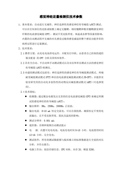
感觉神经定量检测仪技术参数
感觉神经定量检测仪技术参数
1、基本要求:自动进行无痛性、神经选择性的感觉神经传导阈值(sNCT)测试。
可以在任何部位的皮肤或粘膜上确定无髓鞘、细有髓鞘和粗有髓鞘感觉神经纤维的电流感觉阈值(CPT)。
测试不受皮肤厚度、体温或水肿等因素的影响,内置的自动测试程序无痛的对从感觉过敏到感觉减退的整个感觉功能异常的病理过程进行定量测试。
2、技术要求:
2.1携带方便,由充电电池供电运作,并配有打印机、由患者自己控制的遥控
器及配套的CPT 分析及资料库软件。
2.2具有全自动、半自动和手动测试模式以及双盲和单盲测试方法的感觉神经
传导阈值(sNCT)检测仪。
2.3内建的测试模式包括有:神经选择性的感觉神经传导阈值测试模式、疼痛
耐受阈值测试模式(PTT)和区段电流感觉阈值测试模式(R-CPT),并提供实验室研究用的自动化非创伤性的动物反应阈值测试模式(ART)(可选择使用)。
2.4技术指标:
●检测器:通过镀金电极发出无害的经皮电流感觉阈值(CPT)来确定所测
试的感觉神经的传导阈值(sNCT);
●输出频率: 5Hz, 250Hz, 2000Hz 正弦波;
●输出电流: 0-10 mA 恒定交流电,可以自我校准,确保恒定不变的电
流输出,且不受皮肤厚度、阻抗及温度的影响;
●测试分辨率: 0.001 mA;
●遥控器:音频和视频自动测试提示
●电源: 内置可充电电池,电池充电时间8-18 小时,电池使用时间
12-16 小时,完全充电;
●测试软件:所有的测试数据都与临床确立的标准数据进行全面的对比
分析,并作出报告;
●电脑工作站:阅读存储信息,CPU双核、内存2G、硬盘320G。
PCE-VT 2600 振动测试仪说明书

www.pce-industrial-needs.com Tursdale Technical Services Ltd Unit N12B Tursdale Business Park Co. Durham DH6 5PG United Kingdom Phone: +44 ( 0 ) 191 377 3398 Fax: +44 ( 0 ) 191 377 3357 *********************************.uk
http://www.industrial-needs.com/
MANUAL PCE-VT 2600
*********************************.uk 1. Structure .............................................................................................................................. 3 2. Features .............................................................................................................................. 3 3. Operation ............................................................................................................................. 3 4. Capability ............................................................................................................................. 4 5. Maintenance: ....................................................................................................................... 4 a. ISO 2372 Machine Vibration grades (NEMA MG1-12.05) ................................................ 5 b. The max. vibration permitted of motor with power more than 1 hp. ( NEMA MG1-12.05) .5c. The max. vibration permitted of large induction-motor ( NEMA MG1-20.52) .................... 5 d. Max. vibration permitted of squirrel-cage induction-motor(API STD541) ......................... 6 e. ISO./IS2373 quality standard of motor according to swing of vibration speed. ................ 6 f. Non-warranty parts ........................................................................................................... 6 *********************************.uk 1. Structure
PCE Instruments PCE-VT 3700 振动测量仪操作手册说明书

PCE-VT 3700 Vibrationsmessgerät | Vibration MeterBedienungsanleitungUser ManualUser manuals in various languages (français, italiano, español, português, nederlands, türk, polski,русский, 中文) can be found by using our product search on: D e u t s c hE n g l i s hEnglishContents1Safety notes (16)2System description (17)2.1Device (17)2.2Function keys (18)2.3Display (measurement screen) (18)3Specifications (19)3.1Technical specifications (19)3.2Delivery contents (20)3.3Accessories (20)4Getting started (22)4.1Power supply (22)4.2Preparation (22)5Menu (23)5.1Measurement (23)5.2Calibration (26)5.3Settings (27)5.4Manual (28)5.5Info (28)6Operation (29)6.1Measurement screen (29)6.2Preparation (29)6.3Perform measurement (29)7Warranty (30)8Disposal (30)1 Safety notesPlease read this manual carefully and completely before you use the device for the first time. The device may only be used by qualified personnel and repaired by PCE Instruments personnel. Damage or injuries caused by non-observance of the manual are excluded from our liability and not covered by our warranty.∙ The device must only be used as described in this instruction manual. If used otherwise,this can cause dangerous situations for the user and damage to the meter.∙ The instrument may only be used if the environmental conditions (temperature, relativehumidity, …) are within the ranges stated in the technical specifications. Do not expose the device to extreme temperatures, direct sunlight, extreme humidity or moisture. ∙ Do not expose the device to shocks or strong vibrations.∙ The case should only be opened by qualified PCE Instruments personnel. ∙ Never use the instrument when your hands are wet.∙ You must not make any technical changes to the device.∙ The appliance should only be cleaned with a damp cloth. Use only pH-neutral cleaner,no abrasives or solvents.∙ The device must only be used with accessories from PCE Instruments or equivalent. ∙ Before each use, inspect the case for visible damage. If any damage is visible, do notuse the device.∙ Do not use the instrument in explosive atmospheres.∙ The measurement ranges as stated in the specifications must not be exceeded underany circumstances.∙ Non-observance of the safety notes can cause damage to the device and injuries tothe user.We do not assume liability for printing errors or any other mistakes in this manual.We expressly point to our general guarantee terms which can be found in our general terms of business.If you have any questions, please contact PCE Instruments. The contact details can be found at the end of this manual.English 2 System description2.1 DeviceThe vibration meter PCE-VT 3700 is capable of measuring different vibration severity parameters and is thus suitable for machine condition monitoring. The measuring units include vibration acceleration, vibration velocity and vibration displacement. The vibration signal can be evaluated for RMS, peak, peak-peak and crest factor which is shown as the measurement value on the screen. These measurements can be used to detect and identify machine imbalances which can lead to e.g. bearing damage.Apart from a Hold function which freezes the current measurement value, the device also includes a function to show the max value. During a session this function displays the highest measurement value acquired so far in addition to the current measurement value.Another feature which consists of automatic evaluation of the measurement value with regards to the ISO standard 10816-3. When this feature is enabled the measurement value is compared against the three vibration thresholds described in the ISO standard and the current vibration severity zone is displayed through color coding of the value on the screen.1. Display2. Function keys3. Sensor connector4. Vibration sensor5. Magnet adapterFig. 1 Description PCE-VT 3700E n g l i s hFig. 2 Measurement screen2.2 Function keysKeyDescriptionFunctionON/OFF- Turn device on/offMENU - Open main menuBACK - Cancel, return, reset max. valueOK - ConfirmHOLD - Hold current measurement valueUP - Menu upDOWN - Menu downRIGHT - Menu rightLEFT - Menu left2.3Display (measurement screen) 1. Date & time 2. Battery charge 3. Measuring unit 4. Frequency range 5. Parameter 6. HOLD on/off7. Measurement value 8. Max value 9. ISO group10.Vibration severity zone3 Specifications3.1 Technical specificationsE n g l i s h3.2 Delivery contents• 1 x Vibration meter PCE-VT 3700 • 1 x Sensor with spiral cable • 1 x Magnet adapter • 3 x AA batteries• 1 x Quick start guide • 1 x Calibration certificate • 1 x Service bag3.3 Accessories3.3.1Magnet adapter PCE-VT-VMHInstead of a stud bolt the magnet adapter PCE-VT-VMH can be used attach the sensor to magnetic surfaces. 3.3.2Handle PCE-VT-HANDLEThe ergonomic handle which is attached to the sensor and spiral cable can be used in conjunction with the measuring tip to measure in inaccessible locations. 3.3.3Measuring tip PCE-VT-NPFor inaccessible measurement locations or if only a quick, temporary measurement is sufficient, the measuring tip PCE-VT-NP can be used to perform these measurements. The measuring tip should be placed as vertical as possible on the measurement surface in order to receive accurate measurements.English 3.3.4 Vibration calibrator PCE-VC20 / PCE-VC21The vibration meter PCE-VT 3700 can be calibrated with the vibration calibrators PCE-VC20 or PCE-VC21.3.3.5 Instrument case PCE-VT 3700 CASEThe instrument case PCE-VT 3700 CASE is used for safe storage and transport of the vibration meter and its accessories.4 Getting started4.1 Power supplyThree AA-batteries are used to power the vibration meter. The battery compartment is on theback of the device. The device should be turned off before the batteries are replaced. In order to replace the batteries, the two screws which hold the cover in place need to be removed. Afterwards the cover can be removed so the batteries can be inserted in the compartment. The compartment can then be closed by installing the cover and fastening the two screws.The current battery level is displayed in the top right corner of the screen. If the battery charge is insufficient for proper operation of the device the device automatically powers off and the screenbelow is shown on the display.hsilgnEFig. 3 Automatic power off4.2 PreparationConnect the sensor with the spiral cable to the vibration meter before turning it on. The knurlednuts should be tightened to ensure proper connection. In order to turn on the device, the ON/OFFbutton needs to be pressed until the screen backlight turns on and the start-up screen is shown.The start-up screen is shown for about 2 seconds and the device automatically switches to the measurement screen afterwards. The device is turned off by pressing the ON/OFF button untilthe screen backlight turns off. The following icon is displayed on the start-up screen if date andtime need to be set:Fig. 4 Set date & timeEnglish 5 MenuThe main menu can be reached from any screen by pressing the MENU button. The arrow keys are used to navigate the menu items which can be activated with the OK button. The BACK button is used to return from sub menus. The main menu consists of the sub menus Measurement, Calibration, Settings and Info which are explained in detail below. 5.1 MeasurementThe sub menu Measurement is used to configure the different options of the vibration measurement: Measuring unit, parameter, ISO evaluation, display max value.5.1.1 Measuring unitThe measuring unit and the respective frequency range can be adjusted with this menu. The options include acceleration a (10 Hz … 10 kHz), acceleration a (1 kHz … 10 kHz), velocity v (10 Hz … 1 kHz) and displacement d (10 Hz … 200 Hz). This sub menu can also be directly accessed from the main screen by pressing the left arrow key .5.1.2 ParameterThis sub menu is used to adjust the metric of the measured vibration which is displayed as the measurement value on the main screen. It is possible to switch between RMS, peak, peak-peak and crest factor. This sub menu can also be directly accessed from the main screen by pressing the right arrow key .Fig. 5 Measuring unitFig. 6 ParameterE n g l i s h5.1.3 ISO evaluationIn order to enable the automatic evaluation of the current measurement value according to the ISO standard 10816-3, the measuring unit vibration acceleration or vibration velocity in conjunction with the parameter RMS need to be selected. This is necessary since the ISO standard only lists valid vibration severity thresholds for these two combinations. After the correct measurement options were set, the appropriate option for the machine to be measured (group 1 or 2, rigid or flexible mounting) can be selected in this sub menu.When this function is enabled, the name of the enabled group is displayed at the bottom of the main screen together with four color coded items which represent the four vibration severity zones. The current measurement value shown on the screen is compared against the thresholds described in the ISO standard and is automatically color coded according to the thresholds. Additionally, the item which represents the current zone flashes periodically so the vibration severity can be quickly determined.If the automatic evaluation is currently enabled and an incompatible measuring unit (acceleration) or parameter (peak, peak-peak, crest factor) is activated, the evaluation function is automatically disabled and a corresponding hint is displayed on the screen.As described previously the automatic evaluation function requires the measuring unit velocity or displacement in conjunction with the parameter RMS. Otherwise the menu to enable this function cannot be opened and the following hint is displayed on the screen.Fig. 7 Hint ISO evaluation disabledFig. 8 Hint for activation of ISO evaluationMachine groups:∙Group 1: Large machines with nominal power > 300 kW;Electrical machines with shaft height > 315 mmThese machines generally have plain bearings and therated/operating speeds range from 120 RPM to 15,000 RPM.∙Group 2: Machines with nominal power between 15 kW and 300 kW;Electrical machines with shaft height between 160 mm and315 mm.5.1.4 Display max valueThis sub menu is used to activate the display of the max value function. When enabled the max value during a measurement session is displayed under the current measurement value. The BACK button can be used to reset the max value.5.2 CalibrationA vibration calibrator capable of generating a reference vibration of 10 mm/s RMS at 159,2 Hz(e.g. PCE-VC20 or PCE-VC21) is required for the calibration of the vibration meter. The calibration can be started with the sub menu Calibration. The first screen shows the hint regardingthe required reference vibration and the sensor of the vibration meter needs to be mounted onthe vibration calibrator.hsilgnEFig. 9 Hint for required reference vibrationAfter the vibration calibrator was turned on, the calibration can be continued with the OK button.This leads to the calibration screen. This screen again shows the characteristics of the required reference vibration at the top, followed by the current measurement value of the device in a greenfont with the unit mm/s. It is not necessary to adjust the device measurement parameters specifically for the calibration as only the RMS value of the vibration velocity is evaluated duringthis procedure.Fig. 10 Calibration screenHINT: Verify that the required reference vibration is generated by the vibration calibrator before the calibration is performed!English If the current measurement value compared against the reference vibration exceeds the desired tolerance, the device can perform a calibration which can be started by pressing the OK button on the calibration screen and confirming the subsequent dialog.The calibration is performed autonomously by the device and should take less than 5 seconds. After the calibration was finished a pop-up is displayed on the screen with the hint that the calibration was successful as confirmation. Afterwards a short delay the device returns to the main measurement screen.5.3 Settings5.3.1 UnitsThe measurement unit can be switched between the metric system and imperial units.5.3.2 Date & timeThis menu is used to change the date and time which is displayed in the status bar at the top of the screen. The date format can also be changed.5.3.3 Display brightnessThe screen backlight intensity can be adjusted from 10% to 100%.5.3.4 LanguageThis menu is used to switch between different menu languages. Available languages include English, German, French, Spanish, Italian, Dutch, Portuguese, Turkish, Polish, Russian, Chinese and Japanese.5.3.5 Auto power offThis option enables the auto power off function. Available time periods include 1 minute, 5 minutes and 15 minutes. After the set time period has elapsed, the device will automatically turn off and any button press will reset the timer. It is also possible to disable the auto power off function. 5.3.6 Device resetThis menu is used to reset the device to factory settings. Device settings are separate from the calibration and each can be reset individually by selecting the corresponding menu item.A reset of the device settings will load default measurement parameters and reset any remaining menu option to the factory default values. A calibration which may have been performed beforehand is retained.Fig. 11 Confirmation dialogE n g l i s hHINT: If a reset of the calibration is performed, the previously performed calibration will be deleted and a default value for the sensor sensitivity will be selected. It is recommended to perform a calibration after the reset.The reset must be confirmed via the subsequent confirmation dialog when one of the reset options is selected. The device will perform a restart after the reset has been performed.5.4ManualThis sub menu leads to a screen with a QR code. This code can be decoded with a suitable scanner like e.g. a mobile phone and it contains a link which directly leads to the manual of the PCE-VT 3700 for easy access. 5.5InfoThis sub menu shows a screen with the device name and firmware version.Fig. 12 Confirmation dialogEnglish 6 Operation6.1 Measurement screenAfter turning on the device, the main measurement screen is displayed. The mechanical vibration is converted by the sensor into an electrical signal which is subsequently evaluated according to the measurement settings. The result is displayed as the measurement value on the screen and is continually updated with the current value.Default measurement settings (first start or after reset of device settings) consists of the RMS value of vibration velocity in mm/s. When measurement settings are adjusted via the menu, the changes are applied when the screen is returned to the measurement screen and the changes are reflected on the display accordingly.6.2 PreparationDepending on the application and machine to be measured, the desired measurement settings need to be set with the menu. These settings include measuring unit, parameter, units and possibly ISO evaluation or max value.6.3 Perform measurementThe sensor needs to be attached the desired position to perform a measurement. It can be mounted either with a stud bolt or the magnet adapter. If the measuring tip is used in conjunction with the sensor instead of either mounting option, the sensor should be placed as vertical as possible on the measurement surface in order to receive an accurate result.The measurement is performed continuously by the device when on the main measurement screen and no further user input is required.If the ISO evaluation function is enabled, the current measurement value is color coded with regards to the selected thresholds. Additionally, the corresponding vibration severity zone at the bottom of the display flashes periodically which allows for quick identification of the current vibration severity.Fig. 13 Measurement screen7 WarrantyYou can read our warranty terms in our General Business Terms which you can find here: https:///english/terms.8 DisposalFor the disposal of batteries in the EU, the 2006/66/EC directive of the European Parliament applies. Due to the contained pollutants, batteries must not be disposed of as household waste. They must be given to collection points designed for that purpose.For countries outside the EU, batteries and devices should be disposed of in accordance with your local waste regulations.If you have any questions, please contact PCE Instruments.PCE Instruments contact informationGermany France SpainPCE Deutschland GmbH PCE Instruments France EURL PCE Ibérica S.L.Im Langel 4 23, rue de Strasbourg Calle Mayor, 53D-59872 Meschede 67250 Soultz-Sous-Forets 02500 Tobarra (Albacete) Deutschland France EspañaTel.: +49 (0) 2903 976 99 0 Téléphone: +33 (0) 972 3537 17 Tel. : +34 967 543 548Fax: +49 (0) 2903 976 99 29 Numéro de fax: +33 (0) 972 3537 18 Fax: +34 967 543 542*************************************************************/deutsch /french /espanolGermany United Kingdom ItalyPCE Produktions- und PCE Instruments UK Ltd PCE Italia s.r.l. Entwicklungsgesellschaft mbH Unit 11 Southpoint Business Park Via Pesciatina 878 / B-Interno 6Im Langel 26 Ensign Way, Southampton 55010 Loc. GragnanoD-59872 Meschede Hampshire Capannori (Lucca)Deutschland United Kingdom, SO31 4RF ItaliaTel.: +49 (0) 2903 976 99 471 Tel: +44 (0) 2380 98703 0 Telefono: +39 0583 975 114 Fax: +49 (0) 2903 976 99 9971 Fax: +44 (0) 2380 98703 9 Fax: +39 0583 974 824*******************************************************************/deutsch /english /italianoThe Netherlands China Hong KongPCE Brookhuis B.V. PCE (Beijing) Technology Co., Limited PCE Instruments HK Ltd. Institutenweg 15 1519 Room, 6 Building Unit J, 21/F., COS Centre7521 PH Enschede Zhong Ang Times Plaza 56 Tsun Yip StreetNederland No. 9 Mentougou Road, Tou Gou District Kwun TongTelefoon: +31 (0)53 737 01 92 102300 Beijing, China Kowloon, Hong Kong******************Tel: +86 (10) 8893 9660 Tel: +852-301-84912/dutch ********************************************** United States of America TurkeyPCE Americas Inc. PCE Teknik Cihazları Ltd.Şti.711 Commerce Way suite 8 Halkalı Merkez Mah.Jupiter / Palm Beach Pehlivan Sok. No.6/C33458 FL 34303 Küçükçekmece - İstanbulUSA TürkiyeTel: +1 (561) 320-9162 Tel************Fax: +1 (561) 320-9176 Faks*******************************************************.tr/us /turkishUser manuals in various languages (français, italiano, español, português, nederlands, türk, polski, русский, 中文) can be found by using our product search on: Specifications are subject to change without notice.。
- 1、下载文档前请自行甄别文档内容的完整性,平台不提供额外的编辑、内容补充、找答案等附加服务。
- 2、"仅部分预览"的文档,不可在线预览部分如存在完整性等问题,可反馈申请退款(可完整预览的文档不适用该条件!)。
- 3、如文档侵犯您的权益,请联系客服反馈,我们会尽快为您处理(人工客服工作时间:9:00-18:30)。
VPT-I 震动感觉阈值检测仪 VPT-I 数字震动感觉阈值检测仪是一种简单,无创性神经功
能检测仪器。
有主机和检测手柄组成,用于在局部提供震动,通过病人对震动做出的反应,辅助诊断病人是否有神经感应系统疾病!
产品作用 1.VPT-I 数字震动感觉阈值检测仪是一种简单,无创性神经功能检测仪器。
有主机
和检测手柄组成,用于在局部提供震动,通过病人对震动做出的反应,辅助诊断病人是否
有神经感应系统疾病!
2.试用于:周围神经系统的监测
(1) 糖尿病足病筛查
(2)大脑感觉中枢产生的深感觉障碍
(3) 神感受神经纤维病损
(4) 神经再生的研究
(5) 性功能障碍检查
3. 临床应用:
(1)早期发现糖尿病患者感觉的减退和消失
(2) 周围神经病变定量阈值检测
(3)高风险足病筛查
(4) 性功能障碍检查
(5)深感觉神经纤维病损
(6)分析软件形成工作站,储存,打印病理报告
产品简介
震动感觉阈值检查仪(SensiometerA)性能介绍本产品通过数字电路控制手柄震动探头
的振幅大小,可以检查受试者震动感觉阈值(VPT,VibrationPerceptionThreshold),为临
床判断感觉神经功能提供客观的数值,并为周围神经疾病的临床诊断提供帮助。
通过提供
连续的阈值数值,可以针对患者就某种治疗进行长期的跟踪和观察,评价治疗效果。
震动
感觉阈值在已知外周感觉受体正常的情况下。
神经中毒性疾病、神经炎症、全身代谢性疾病,等等。
多神经病变的临床改变常常是先
从感觉神经开始,然后是影响到运动神经。
然而临床上,患者很少因为感觉的异常而去医
院就诊,多是病变累及运动神经后才去就诊。
这是因为神经病变引起的早期感觉异常,往
往不易被患者所察觉。
这样会延误神经疾病的早期诊断和治疗。
因此,当临床怀疑某个病
人有神经病变时,就应及时进行各种感觉刺激的检查,震动感觉的检查就是其中之一。
震动感觉检查是感觉神经检查方法中最常使用的方法。
以往常用 128Hz 音叉震动方法检查受试者的震动感觉,虽然它可以作为一种简便的震动感觉检查方法,但是却无法提供震
动阈值(VPT, VibrationPerceptionThreshold)检查所需的强弱数值。
而且其准确性一直被许
多医务人员所置疑。
正因为如此,传统音叉震动感觉检查只能定位为一种粗略的定性方法,
正逐渐被震动感觉阈值(VPT)检查所代替。