Asymmetric hydrogenation
一种双膦配体的合成
Alkoxy substituted MeO-BIPHEP-type diphosphines ligands forasymmetric hydrogenation of aryl ketonesMeng Lin Ma a ,b ,Zong Hai Peng b ,Yu Guo b ,Li Chen b ,Hua Chen b ,*,Xian Jun Li baDepartment of Chemistry,Xihua University,Chengdu 610039,ChinabKey Lab of Green Chemistry and Technology,Ministry of Education,The Institute of Homogeneous Catalysis,Faculty of Chemistry,Sichuan University,Chengdu 610064,ChinaReceived 9October 2009AbstractIn this paper,a series of optically active MeO-BIPHEP-type ligands,(S )-6,60-dimethoxy-2,20-bis(di-p -alkoxyphenylphosphine)-1,10-biphenyl were synthesized and used to prepare the ruthenium complex.The effects of para -substituted were observed,the results showed that the ruthenium catalysts [diphosphine RuCl 2diamine]containing both t -Bu and i -Pr substitutions have better activities and enantioselectivities than the non-substituted ruthenium catalysts in the asymmetric hydrogenation of acetophenone.#2010Hua Chen.Published by Elsevier B.V .on behalf of Chinese Chemical Society.All rights reserved.Keywords:Aryl ketone;Asymmetric hydrogenation;Biaryl phosphines ligands;Ruthenium complexAsymmetric hydrogenation has become increasingly popular for producing enantiomerically pure compounds in pharmaceutical and chemical industries.Chiral diphosphine ligands such as BINAP 1a ,BIPHEMP 2a ,P-Phos 3a and MeO-BIPHEP 4a (Fig.1)have demonstrated their high efficiencies and high enantioselectivities in Rh(I)and Ru(II)catalyzed homogeneous asymmetric hydrogenation of olefins,ketones and imines [1].In 1995Noyori reported that ketones with no secondary binding functionality could be effectively hydrogenated in the presence of ruthenium catalysts.These are based on a ruthenium metal centre bearing a chiral diphosphine and a chiral diamine ligand in the presence of a base (such as t -BuOK or KOH).The asymmetric hydrogenation of a wide range of unfunctionalised ketones now became possible,without the previous need to have a secondary binding group on the substrate [2].Ruthenium precatalysts [diphosphine RuCl 2diamine]formed by the non-substituted biaryl diphosphines ligands MeO-BIPHEP 4a or BINAP 1a and the diamine DPEN 5(Fig.1)showed better activities and moderate steric selectivities for the asymmetric hydrogenation of acetophenone.This seminal discovery has led to the development of the first highly practical and selective methodology for homogeneous asymmetric ketone hydrogenation in the past few years.It has been reported that 3,5-disubstituted arene groups generally impart higher activities and selectivities to the catalyst [3].The 3,5-disubstituted biaryl diphosphines ligands,such as xyl-BINAP 1b [4],xyl-P-Phos 3b [5],xyl-/locate/ccletAvailable online at Chinese Chemical Letters 21(2010)576–579*Corresponding author.E-mail address:mmlchem@ (H.Chen).1001-8417/$–see front matter #2010Hua Chen.Published by Elsevier B.V .on behalf of Chinese Chemical Society.All rights reserved.doi:10.1016/let.2010.01.030MeO-BIPHEP 4b [6]and xyl-TetraPHEMP 2b [7](Fig.1),were used in asymmetric hydrogenation of ketones and get good results,in which the steric influence of the 3,5-disubstituted was investigated.Due to the importance of the nature of substituents on the phosphorus atoms,we investigated the influence of newly designed MeO-BIPHEP-type atropisomeric diphosphines with para -alkoxy phenyl group at each of the phosphorus atom (Fig.2).The different structures of the alkoxy are expected to provide an opportunity to investigate the influence of the para -substituent in the asymmetric hydrogenation of ketones.In this paper,a series of chiral diphosphines 6,60-dimethoxy-2,20-bis(di-p -alkoxyphenylphosphine)-1,10-biphenyl were synthesized by an improvement way (Scheme 1)based on the Schmid method [8]and our improve way [9].In order to evaluate alkoxy substituted ligands,their corresponding ruthenium complexes were prepared according to literature methods [10](Scheme 2)and tested on the hydrogenation of acetophenone.Parallel experiments were performed to make direct comparison between our catalysts and reported ones.Basic reaction conditions were first optimized using acetophenone as substrate and p -methoxy-MeO-BIPHEP 4c phosphine ligand complex as a catalyst.M.L.Ma et al./Chinese Chemical Letters 21(2010)576–579577Fig.1.Ligands used for ketone hydrogenationcatalysts.Fig.2.Our biaryl diphosphineligands.Scheme 1.Reagents and conditions:(a)P(OEt)3,anhydrous NiCl 2,1408C,1h,87%yield or microwave,5min,94%yield,(b)(1)LDA in THF,À788C,(2)anhydrous FeCl 3in THF,À788C to rt.,16h,49%yield or (1)LTMP (BuLi +2,2,6,6-tetramethylpiperidine)in THF,À788C,(2)anhydrous FeCl 3in THF,À788C to rt.,16h,58%yield,(c)(1)(À)-DBTA in CH 2Cl 2/Et 2O,(2)10%NaOH/CH 2Cl 2,>99%ee,(d)SOCl 2,DMF,99%yield,(e)ArMgBr in THF,À788C to rt.,3h,95–68%yield or ArLi in THF,À788C to rt.,0.5h,46–35%yield,(f)HSiCl 3,Et 3N in toluene,reflux,98%yield,>99%ee.The catalytic activities of these ruthenium complexes in the hydrogenation of acetophenone were tested in i -Pr-OH,with a substrate/catalyst/base ratio (S/C/B)of 3000/1/100,at 508C and under 40bar of hydrogen (Table 1).The same ruthenium complexes were prepared with the MeO-BIPHEP in order to compare the activity and selectivity of ligands.As we have already observed with ligands 4c ,4d and 4e ,these alkoxy substituted almost have no influence either on the activity or on the selectivity (Table 1,entry 2,3and 4).Moreover some other para -substituent of the diphosphine ligands has the influence in the asymmetric hydrogenation of ketones.In our reaction conditions,the non-substituted MeO-BIPHEP ligands 4a provided 99%conversion to products and gave 81%ee at 208C (Table 1,entry 1).Different results were obtained because of their different chemical structures.The ligands substituted by para-t -Bu 4h and para-i -Pr 4f both gave good ee than non-substituted one,particularly the t -Bu-MeO-BIPHEP 4h could get 99%conversion with 97%ee (Table 1,entry 7).These results clearly indicated the strong influence of para -substituent with steric hindrance on the enantioselectivity of the reaction.With the optimal reaction conditions in hand,ligand 4h was used in the hydrogenation of a series of acetophenones derivatives (Table 2,entries 1–10).Excellent enantioselectivities ee were observed.The best result was hydrogenation of o -bromoacetophenone (Table 2,entry 7),in which the conversion to products was >99%with 99%ee.The o -chloroacetophenone (Table 2,entry 8)and o -trifluoromethylacetophenone (Table 2,entry 6)could get better ee at 97%.These results are comparable to the best results reported to date.In summary,we have investigated the influence of the para -substituent in the asymmetric hydrogenation of ketones,the results showed that new ruthenium catalysts [diphosphine RuCl 2diamine]containing the p -t -Bu-or p -i -Pr-substituted MeO-BIPHEP ligand were better than non-substituted ones in both activities and enantioselectivities.Further study will be focused on the synthesis and applications of other ortho -substituted MeO-BIPHEP ligands.M.L.Ma et al./Chinese Chemical Letters 21(2010)576–579578Scheme 2.Reagents and conditions:(a)DMF and [Ru(benzene)Cl 2]21008C,25min and (b)(S,S )-DPEN,258C,5h.The solvent DMF was removed by evaporated at 308C under reduced pressure.Table 1The effect of the para -alkoxy chain in the hydrogenation ofacetophenone..Entry Phosphine R 1R 2Con.(%)ee (%)a 14a CH 3H 9981b 24c CH 3H 998234d CH 3H >998444e CH 3H >998454f CH 3H >999264g CH 3H >998774h CH 3H >999784iCH 3H2977aReactions were run under 3Mp H 2and 208C in 50mL magnetically stirred Parr pressure vessels and in 12h.S/C/B 3000/1/100.Conversion and ees were determined by GC analysis (Chirasil DEX-CB column).bHenschke et al.reported 84%ee using RuCl 2[(S )-MeO-BIPHEP][(S,S )-DPEN]precatalyst and t -BuOK as base [7].M.L.Ma et al./Chinese Chemical Letters21(2010)576–579579 Table2The results of hydrogenation different acetophenones derivatives.Entry Phosphine R1R2Con.(%)ee(%) 1t-Bu-MeO-BIPHEP(4h)CH2CH3H>99822CH2(CH3)2H19783CH3p-CH3O89744CH3p-CF3>99845CH3o-CH3O53476CH3o-CF3>99987CH3o-Br>99998CH3o-Cl>99979CH3o-F986410CH3o-OH00 Reactions were run under3Mp H2,208C in50mL magnetically stirred Parr pressure vessels and in12h.S/C/B3000/1/100.Conversion and ees were determined by GC analysis(Chirasil DEX-CB column).AcknowledgmentsWe thank the NSFC(No.20272037),the Doctor’s Foundation of Education Ministry of China(No.20030610022) and Foundation of Xihua University(No.R0723315)and(No.07ZA109)for thefinancial support of this work. References[1](a)W.J.Tang,X.M.Zhang,Chem.Rev.103(2003)3029;(b)M.MacCarthy,P.J.Guiry,Tetrahedron57(2001)3809;(c)X.M.Zhang,Enantiomer4(1999)541.[2](a)R.Noyori,Angew.Chem.,Int.Ed.41(2002)2008;(b)R.Noyori,T.Ohkuma,Angew.Chem.,Int.Ed40(2001)40;(c)Z.G.Antonio,H.William,G.Michelle,et al.Platinum Met.Rev.49(2005)158.[3]P.Dotta,A.Magistrato,U.Rothlisberger,et anometallics21(2002)3033.[4]T.Ohkuma,M.Koizumi,K.Muniz,et al.J.Am.Soc.Chem.124(2002)6508.[5](a)J.Wu,H.Chen,W.Kwok,et .Chem.67(2002)7908;(b)J.Wu,J.X.Ji,R.Guo,et al.Eur.J.Chem.9(2003)2963.[6]B.H.Lipshutz,K.Noson,W.Chrisman,et al.J.Am.Soc.Chem.125(2003)8779.[7](a)J.P.Henschke,Z.G.Antonio,P.Moran,et al.Tetrahedron Lett.44(2003)4379;(b)J.P.Henschke,M.J.Burk,C.G.Malan,Adv.Synth.Catal.345(2003)300.[8](a)R.Schmid,E.A.Broger,M.Cereghetti,Pure Appl.Chem.68(1996)131;(b)E.A.Broger,J.Foricher,R.Schmid,US5,274,125,1993,Chem.Abstr.1993,118,P59878a;;(c)J.Foricher,B.Heiser,R.Schmid,US5,302,738,1994,Chem.Abstr.1993,118,P147774u;;(d)londe,5,536,858,1996,Chem.Abstr.1996,124,P8995c.[9]M.L.Ma,Z.H.Peng,H.Chen,J.Chin.Chem.24(2006)1391.[10]H.Doucet,T.Okhuma,R.Noyori,Angew.Chem.,Int.Ed.37(1998)1703.。
全球天然氢气勘探开发利用进展及中国的勘探前景
第36卷第2期2024年3月岩性油气藏LITHOLOGIC RESERVOIRSV ol.36No.2Mar.2024收稿日期:2023-11-01;修回日期:2023-11-12;网络发表日期:2023-11-16基金项目:国家自然科学基金“特提斯演化控制下的油气差异富集机理与勘探领域”(编号:92255302)和中国石油集团公司科技重大专项“海外油气地质新理论资源评价新技术与超前选区研究”(编号:2023ZZ07)联合资助。
第一作者:窦立荣(1965—),男,博士,教授级高级工程师,主要从事全球油气资源评价与海外重点领域油气勘探关键技术研究。
地址:(100083)北京市海淀区学院路20号。
Email :**********************.cn 。
通信作者:李博(1993—),男,博士,工程师,主要从事油气伴生资源勘探与评价技术研究。
Emali :**********************.cn 。
文章编号:1673-8926(2024)02-0001-14DOI :10.12108/yxyqc.20240201引用:窦立荣,刘化清,李博,等.全球天然氢气勘探开发利用进展及中国的勘探前景[J ].岩性油气藏,2024,36(2):1-14.Cite :DOU Lirong ,LIU Huaqing ,LI Bo ,et al.Global natural hydrogen exploration and development situation and prospects in China [J ].Lithologic Reservoirs ,2024,36(2):1-14.全球天然氢气勘探开发利用进展及中国的勘探前景窦立荣1,刘化清1,李博1,齐雯1,孙东1,尹路1,韩双彪2(1.中国石油勘探开发研究院,北京100083;2.中国矿业大学(北京)地球科学与测绘工程学院,北京100083)摘要:在全球能源脱碳背景下,天然氢气作为一种一次能源,因其零碳、可再生的优点而备受关注,但中国目前还未开展专门针对天然氢气的勘探工作。
酸化吹气-重铬酸钾法测定高氯地表水中化学需氧量
化学分析计量CHEMICAL ANALYSIS AND METERAGE第30卷,第6期2021年6月V ol. 30,No. 6Jun. 202162doi :10.3969/j.issn.1008–6145.2021.06.014酸化吹气–重铬酸钾法测定高氯地表水中化学需氧量达莉芳,范丽华,施玉格,段小燕,李刚,李媛,贺承启(新疆维吾尔自治区生态环境监测总站,乌鲁木齐 830011)摘要 建立酸化吹气–重铬酸钾法测定高氯地表水化学需氧量(COD Cr )的方法。
通过在高氯水样中加入适宜浓度的硫酸,在加热及吹气条件下使干扰物氯离子以氯化氢的形式释放出,并用氢氧化钠溶液吸收,再采用重铬酸盐法对驱氯后的样品进行COD Cr 的测定。
结果表明,在优化条件下,当取样体积为10.0 mL 时,本方法的检出限为4 mg /L ,测定结果的相对标准偏差为5.2%~13.5%(n =6),与理论值的相对误差为–2.0%~4.3%。
该方法适用于氯离子质量浓度为1 000~100 000 mg /L 的地表水中化学需氧量的测定。
关键词 氯;地表水;化学需氧量;酸化吹气–重铬酸钾法中图分类号:O661.1 文献标识码:A 文章编号:1008–6145(2021)06–0062–05Determination of chemical oxygen demand in high chlorine surface waterby blow–acidizing–dichromate methodDa Lifang, Fan Lihua, Shi Yuge, Duan Xiaoyan, Li Gang, Li Yuan, He Chengqi(Xinjiang Uygur Autonomous Ecological Environmental Monitoring Station, Urumqi 830011, China )Abstract A method was developed for determination of the chemical oxygen demand(CODCr) in high chlorine surface water by blow–acidizing–dichromate method. By adding sulfuric acid of speci fic concentration to the water sample with high concentration of chloride ion, the interfering chloride ion was released in the form of hydrogen chloride under heating and air blow conditions, and absorbed by sodium hydroxide solution. CODCr of the sample was determined by dichromate method after chloride removal. The results show that the detection limit of this method was 4 mg /L, the relative standard deviation of determination results was 5.2%–13.5%(n =6) and the relative error with the theoretical value was from –2.0% to 4.3% when the sample volume was 10.0 mL under optimized conditions. The method is suitable for the determination of COD Cr in surface water with the mass concentration of chloride ion between 1 000 mg /L and 100 000 mg /L.Keywords chlorine; surface water; chemical oxygen demand; blow–acidizing–dichromate method化学需氧量(COD Cr )是指在一定条件下,经重铬酸钾氧化处理时,与水样中的溶解性物质和悬浮物所消耗的重铬酸盐相对应的氧的质量浓度,以 mg /L 表示[1]。
HOMOGENEOUS ASYMMETRIC HYDROGENATION CATALYST

专利名称:HOMOGENEOUS ASYMMETRICHYDROGENATION CATALYST发明人:SHIMIZU, Hideo,IGARASHI,Daisuke,KURIYAMA, Wataru,YUSA, Yukinori 申请号:JP2006313510申请日:20060706公开号:WO07/007646P1公开日:20070118专利内容由知识产权出版社提供摘要:Disclosed is a homogeneous hydrogenation catalyst, in particular a homogeneous asymmetric hydrogenation catalyst containing an asymmetric copper complex having a chiral ligand. This catalyst is useful for hydrogenation reactions, particularly for asymmetric hydrogenation reactions. In addition, this catalyst is available comparatively easily and economical, while having good workability. Also disclosed is a method for producing a hydride of an unsaturated compound, particularly a method for producing an optically active compound having high optical purity with high yield by using the above-described catalyst.申请人:SHIMIZU, Hideo,IGARASHI, Daisuke,KURIYAMA, Wataru,YUSA, Yukinori地址:37-1, Kamata 5-chome, Ohta-ku, Tokyo 1448721 JP,c/o TAKASAGO INTERNATIONAL CORPORATION, Central Research Laboratory, 4-11, Nishiyawata 1-chome, Hiratsuka-shi, Kanagawa 2540073 JP,c/o TAKASAGO INTERNATIONAL CORPORATION, Central Research Laboratory, 4-11, Nishiyawata 1-chome, Hiratsuka-shi, Kanagawa 2540073 JP,c/o TAKASAGO INTERNATIONAL CORPORATION, Central Research Laboratory, 4-11, Nishiyawata 1-chome, Hiratsuka-shi, Kanagawa 2540073 JP,c/oTAKASAGO INTERNATIONAL CORPORATION, Central Research Laboratory, 4-11, Nishiyawata 1-chome, Hiratsuka-shi, Kanagawa 2540073 JP国籍:JP,JP,JP,JP,JP代理机构:IWATANI, Ryo更多信息请下载全文后查看。
《文献信息检索与利用》考试试题答案
考试说明:①综合成绩总分100分,分为平时成绩(占综合成绩的40%)和期末考试试卷成绩(占综合成绩的60%)。
②要求认真审题,独立完成,试卷及作业雷同者、抄袭者和被抄袭者均不得分!!!③要求交打印稿和电子稿。
可先在电脑上做好后再打印出来,注意排版整洁清晰,字体五号字,页边距可设为2×2×2×2。
④考卷WORD文档名称和发送EMAIL标题名一律为“学号+姓名+系部”,如:200942058丁月_计算机科学系。
发送至huadanduoji@.⑤考试时间为9月5日—8日,8日16:30前将考试卷交任课教师处。
一、检索题(80分)。
(以下题如果文字不足以说明,可以采用截图表示。
)1、搜索引擎题。
(20分)(1)在中国教育网站内搜索有关“信息检索”方面的doc\pdf\ppt格式的文献,给出检索式。
(5分)答:信息检索filetype:doc信息检索filetype:ppt信息检索filetype:pdf(2)对本专业的“门户网站”进行搜集,列出你认为最有价值的2个门户网站的名称及网址,并说明选择它的理由。
(5分)答:1)有机化学网:/理由:有机化学网是国内最大的化学网站,内有最丰富的化学技术文章、资料、信息、资讯,最全面的有机化合物库,最权威的化学品供求平台2)化学学科网:/理由:化学学科网作为国内最大的教育门户网站,拥有权威、丰富、及时的独家教育资源。
当前注册会员400多万人,并参与资料上传,同时有千余名一线教师共同审核维护。
每日更新资料数2000多套,非常活跃。
(3)请搜索“中国商标网”网站并用该网站检索绍兴咸亨酒店食品有限公司的商标图案和专用权期限;(5分)答:绍兴咸亨酒店食品有限公司商标如右图:专用期限权:2004 年9 月28 日至2014 年9 月27 日(4)请运用GOOGLE学术搜索,检索近3年内标题内含有“物联网”和“移动通信”方面的学术论文,请打开其中一篇论文全文,把其题名、作者、单位、中英文关键词和摘要、分类号及其一级标题复制粘贴如下。
纳米压痕 纯铁 氢 硬度 位错

Recent developments in the study of hydrogen embrittlement:Hydrogeneffect on dislocation nucleationAfrooz Barnoush *,Horst VehoffSaarland University,Department of Materials Science,Bldg.D22,P.O.Box 151150,D-66041Saarbruecken,GermanyReceived 11March 2010;received in revised form 30May 2010;accepted 30May 2010Available online 2July 2010AbstractIn this paper,the intrinsic complexities of the experimental examination of hydrogen embrittlement are discussed.On the basis of these complexities,an experimental approach,in situ electrochemical nanoindentation,is proposed and performed on different materials.This technique is capable of registering the onset of plasticity in extremely small volumes,namely perfect crystals in hydrogen-free and charged conditions.It is shown that hydrogen reduces the required stress for the onset of plasticity,i.e.homogeneous dislocation nucle-ation by reduction in the shear modulus,dislocation line energy and stacking fault energy.The change in the shear modulus can be related to reduction in crystal cohesion whereas the reduction in dislocation line energy and stacking fault energy are explained by the defactant concept,i.e.reduction in the defect formation energy in the presence of hydrogen.Thus,neither hydrogen-enhanced dec-ohesion nor hydrogen-enhanced plasticity,but the reduction in the cohesion and defect formation energy are responsible for hydrogen embrittlement.Ó2010Acta Materialia Inc.Published by Elsevier Ltd.All rights reserved.Keywords:Hydrogen embrittlement;Nanoindentation;Yield phenomena;Electrochemistry;Dislocation nucleation1.IntroductionHydrogen embrittlement is a severe environmental type of failure that affects almost all metals and alloys.With advancing technology,the use of high-strength structural materials for lightweight construction and energy conser-vation becomes a necessity.In spite of the success of mate-rials scientists in developing alloys with outstanding combinations of high tensile strength and high fracture toughness,hydrogen embrittlement still has a widespread effect that severely degrades the fracture resistance of these alloys.On the other hand,with the depletion of fossil fuels,mankind is searching for other sources of energy.Hydro-gen is believed to be a possible future energy source and it is very possible that a “hydrogen economy ”will be real-ized within the next 50years.In such a scenario,large-scale production,storage,transportation and use of hydrogenwill become necessary.However,the problems in materials caused by hydrogen embrittlement,reported as early as 1875by Johnson [1],could limit the progress of such an economy.Since Johnson first reported on hydrogen embrittlement,various strong views on the mechanisms of hydrogen embrittlement have been vigorously discussed and thoroughly reviewed in the literature [2–4].Because of the technological importance of hydrogen embrittlement,many people have explored the nature,causes and control of hydrogen-related degradation of metals [5–7].This has resulted in an enormous number of sometimes controver-sial findings and/or interpretations.Moreover,frequently an ad hoc approach,focusing on urgent technical problems at hand,is adopted which raises the question of how this isolated case or interpretation really reflects on any basic,general concepts.It thus seems apparent that the findings gathered so far cannot be accounted for by a single domi-nant mechanism.As an example,Fig.1shows the results of conventional hydrogen embrittlement testing of 34different grades of1359-6454/$36.00Ó2010Acta Materialia Inc.Published by Elsevier Ltd.All rights reserved.doi:10.1016/j.actamat.2010.05.057*Corresponding author.E-mail address:a.barnoush@matsci.uni-sb.de (A.Barnoush)./locate/actamatActa Materialia 58(2010)5274–5285steel within465test runs[8].The embrittlement index shown in Fig.1is the reduction in the fracture area in hydrogen-charged vs.hydrogen-free conditions during uni-axial tensile tests.The scatter observed within the results shown in Fig.1demonstrates the need for a new experi-mental approach to the investigation of hydrogen embrit-tlement.It is necessary tofind the source of this scatter in conventional hydrogen embrittlement testing methods. In this paper we will briefly review the different experimen-tal approaches used to study hydrogen embrittlement with a special focus on in situ local examination methods of hydrogen–dislocation interactions due to the conclusive role of dislocations in fracture and hydrogen embrittlement aspect is the wide range of intrinsic/extrinsic variables con-cerning the material itself.The experimental approach for examination of hydrogen embrittlement is based on the elimination of diverse factors within these three aspects. For example,let us consider uniaxial straining of a single crystal sample combined with controlled hydrogen charg-ing on the surface.The uniaxial stressfield simplifies the stress condition,i.e.the mechanical aspect of hydrogen embrittlement,in the e of a single crystal and con-trolled hydrogen charging condition reduces the complexi-ties due to the material and environmental aspects of hydrogen embrittlement in the test.Unfortunately,due to the large difference in the scale of these aspects controlling the process of hydrogen embrittlement,this experimental methodology is not very successful.The uniaxial stressfield of the above-mentioned example is not uniform,unlike the scale of hydrogen interacting with defects like dislocations and vacancies.This problem becomes more complicated as the microstructure becomes more complex with the intro-duction of grain boundaries,pores,second phases,etc. On the other hand,surface hydrogen charging of macro-scopic samples results in a concentration gradient,which again can override the microscopic process of hydrogen embrittlement.Additionally,microstructural features like dislocations,grain boundaries and interfaces can interact with hydrogen diffusion by providing faster diffusion routes or acting as traps for hydrogen.Superimpose upon this theFig. 1.The hydrogen embrittlement index measured by conventionalmechanical testing for34different grades of steel within465test runsFig.2.Global description of hydrogen embrittlement interaction aspects.Materialia58(2010)5274–52855275grain boundary fracture,enhanced shear or enhanced localized microvoid formation,or all of the above.One possible solution to these problems,arising from the experimental methodology used for studying hydrogen embrittlement,is the local examination of the hydrogen effect.This entails reducing the scale of the testing method down to the microstructural level such that all three con-trolling aspects of hydrogen embrittlement(Fig.2)can be defined within the test.Few attempts of this kind of approach have been done previously.Vehoffand Neumann [9]developed a method for studying crack propagation in a controlled environment under controlled plastic strain con-ditions.This method was used to study the hydrogen effect on crack growth mechanisms in Fe–2.6%Si[10]and Ni [11].In their experiments they controlled:(i)environmental aspects by using an ultrahigh-vacuum chamber and con-trolling the partial pressure of hydrogen;(2)mechanical aspects by controlling plastic strain and confining the stress to a smallfield ahead of the crack;and(iii)material aspects by selection of specifically oriented single crystals and focusing on the fracture process zone(Fig.3).Through these perfectly defined experimental conditions they were able to propose a model based on hydrogen-enhanced dec-ohesion(HEDE)and hydrogen trapping in front of a crack tip in the fracture process zone[10,11].Another intelligent experimental approach for small-scale observation of hydrogen effects on mechanical prop-erties was use of in situ straining tests in an environmental transmission electron microscope(TEM)developed by Birnbaum and Sofronis[12].With this technique it was possible for thefirst time to directly observe the effect of hydrogen on dislocations.Unfortunately,there are some uncertainties within the experimental conditions of this technique which must be mentioned here:(i)The electron beam dissociates hydrogen molecules to produce atomic hydrogen.Bond et al.[13]determined that the fugacity of the dissociated hydrogen was between30and750MPa. (ii)Since mode III(shear off)is usually easier in thinfilms, crack growth experiments under a defined mode I loading are very difficult to realize and therefore interpretation of the crack growth results become very difficult.(iii)Field of view is limited to the transparent region of the sample.By the introduction of micro-and nanoscale mechanical testing methods,like instrumented nanoindentation(NI) and nanoindenting atomic force microscopy(NI-AFM),a new era in mechanical testing of extremely small volumes started[14].Gerberich et al.[15]was thefirst one who men-tioned the potential application of micromechanical tests for the examination of hydrogen embrittlement.Since then, several researchers have used the NI technique to probe the effects of hydrogen on mechanical properties[16–20].The main advantage of the NI technique is its capability to resolve the dislocation nucleation in samples with low dis-location density[21,22].Additionally,analytical solutions for stress underneath the tip prior to dislocation nucleation within the elastic deformation are available,so the mechan-ical aspects of the experiments can be defined.The volume probed during the test is extremely small and can be char-acterized by means of different techniques,like electron backscatter diffraction(EBSD)and electron channeling contrast[23],and therefore,material aspects can be resolved.The referenced studies[16–20]used ex situ hydro-gen charging techniques which resulted in uncertaintiesFig.3.Hydrogen effect on the crack tip opening angle in:(a)vacuum and(b)hydrogen atmosphere.Sharpness of the crack tip in stressed Fe–3wt.%single crystal increases progressively with increasing hydrogen pressure[10].Table1Summary of the high-resolution testing methods used for local examination of hydrogen embrittlement. Experimental approach Different aspects of the hydrogen embrittlementMechanical Environmental MaterialIn situ crackpropagation test Defined and analyticallycan be treatedDefined Defined in the case of macroscopic single crystals withspecific orientation,very hard to apply on complexmicrostructuresIn situenvironmentalTEM tests Undefined Undefined due to dissociation of Hmolecules by electron beam(low pressure,very high fugacity)Defined with very high-resolution but only within thefield of viewNanoindentation on ex situ chargedsamples Before pop-in is definedand can analytically betreatedUndefined,due to out gassing andconcentration gradientPerfect defect-free crystalIn situ ECnanoindentation Before pop-in is definedand can analytically betreatedDefined Perfect defect-free crystalMaterialia58(2010)5274–5285within the hydrogen concentration especially near the sur-face of the sample where the mechanical testing was carried out.We solved this problem by performing in situ ECNI tests while the surface hydrogen concentration was kept constant by setting the surface electrochemical potential inside the proper electrolyte[24–26].Table1summarizes the local high-resolution techniques for examination of hydrogen embrittlement.A comparison of these methods shows the advantage of ECNI in provid-ing the required conditions to perform a defined experi-ment in accordance with different aspects of hydrogen embrittlement.In this paper,we report the results of ECNI tests on different metals with different hydrogen embrittle-ment susceptibilities.It will be shown that ECNI is capable of quantitatively resolving the sensitivity to hydrogen embrittlement.3.Experimental3.1.MaterialsThe materials used in this study and the electropolishing parameters and electrochemical hydrogen charging condi-tions for each are summarized in Tables2and3.The sin-gle-crystal specimens were cut by spark erosion from large single crystals with a misalignment of less than2°controlled by EBSD.The polycrystalline specimens were cut from samples with large grains a few millimeters in diameter which act like a single crystal during NI when all tests are performed in the same rge grains or single crystals eliminate the scatter in the data due to orien-tation differences.The samples were mechanically polished down to0.25l m.Afterwards,samples were annealed at 80%of the melting temperature in a vacuum greater than 10À6mbar for24h and cooled in the furnace in order to minimize the lattice defect density.Immediately before indentation the samples were electropolished according to the parameters given in Table2to have a well-defined reproducible surface condition.Special attention was paid to surface preparation since,as mentioned before,a defect-free and low-roughness surface is necessary in order to observe the dislocation nucleation during NI.When examined with an AFM,the sample surface had an root-mean-square roughness of less than1nm,and asperities or steps appeared infrequently on the surface.3.2.InstrumentationThe experiments were performed with a Hysitron Tribo-ScopeÒin conjunction with a Digital Instruments Nano-scope IIÒand a Hysitron TriboIndenterÒ.The indenter, designed especially for tests in liquid,had a Berkovich or conical diamond tip(see Table3).For the NI-AFM system, a three-electrode electrochemical setup with a platinum counter electrode and an Ag/AgCl reference electrode was developed,as shown schematically in Fig.4.Consequently, all the electrochemical potentials in this work are reported against an Ag/AgCl reference electrode.A Bank Elektronik TG97potentiostat was used to control the electrochemical potentials,and the electrochemical data were recorded on a PC using an AD–DA interface.The cell was made from Tef-lon e,and made tofit into the nanoindenter sample holder. Nanoindentation tests were made inside this electrochemi-cal cell while the sample was covered with approximately 2mm of electrolyte.The whole system was put into a cham-ber containing a protective atmosphere of nitrogen and helium in order to eliminate the oxygen effect in the electro-chemical reaction.The solution was injected from outside the chamber through a polyethylene tube connected to a MicroFil e pipette.There are additional concerns that arise when indenting in a liquid environment due to the capillary and buoyancyTable2Summary of the samples studied and their electropolishing conditions.Material Purity Microstructure Electropolishing conditionSolution Potential(V)Temperature(°C)Time(s) Copper Zone refined(111)H3PO4/ethanol202030 Aluminum99.991mm grains HClO4/ethanol40030Fe–3wt.%Si See Table41mm grains H2SO4/CH3OH121060FeAl(40at.%Al)Zone refined(100)H2SO4/CH3OH351090 Nickel Zone refined(111)H2SO4/CH3OH301560 Table3Summary of the electrochemical hydrogen charging and discharging(passivation)conditions.Material Test solution pH H-charging potential Passivation potential Indenter tip Copper Borate buffer9À1000mV250mV Berkovich Aluminum Borate buffer9À1250mV OCP Berkovich Aluminum0.05M Na2SO46OCP250mV Berkovich Fe–3wt.%Si Borate buffer9À1000mV n.a.Berkovich FeAl0.05M Na2SO46À1100mV100mV Conical Nickel0.05M Na2SO46À1000mV500mV BerkovichA.Barnoush,H.Vehoff/Acta Materialia58(2010)5274–52855277forces acting on the tip.To overcome this,the surface is first engaged with a higher set point of contact force.The tip is then moved a few nanometres away from the surface and the forces on the tip balance while it rests above the surface.After this procedure the surface can be easily engaged as usual.Another important concern during the in situ ECNI test is cleanliness.Therefore,all electrolytes were prepared from analytical grade compounds and dou-ble-distilled water.Prior to the tests,the electrochemical cell was cleaned in piranha acid to remove most organic matter and to make it hydrophilic and water compatible.The tip and its shaft were also cleaned carefully before each test in a mixture of ethanol and isopropanol and then in double-distilled water.A clean tip shaft reduces the capil-lary forces acting on it and reduces the probability of dis-engagement of the tip during surface imaging inside the solution.A low impurity content in the electrolyte inhibitsthe deposition of these impurities during electrochemical polarization of the surface.The electrolyte pH and compo-sition should also be selected very carefully to inhibit any possible corrosion and surface roughening.Hence,these parameters are selected for each sample individually.4.Results 4.1.CopperCopper is known for its very low hydrogen solubility and diffusivity.DeWulf and Bard [27]showed that without hydrogen recombination poisons (e.g.As 2O 3)no detectable hydrogen concentration develops in copper.This makes the copper a proper calibration material for in situ ECNI tests,where no effect of cathodic charging should be observed.Typical load–displacement (L –D )curves under cathodic and anodic potentials are given in Fig.5.4.2.AluminumAluminum is a reactive metal protected by a thin stable oxide layer with semi-conductive properties.At potentials cathodic to the open circuit potential (OCP)of Al,cathodic hydrogen evolution due to the reduction of hydrogen ions and water occurs simultaneously with anodic oxidation and dissolution processes [28].This makes the electrochem-ical hydrogen charging of Al without damaging the surface difficult.Therefore,an alternative method controlling the pH of the solution was developed and used for hydrogen charging of Al [29].It is well known that oxide-covered metals immersed in aqueous solutions terminate in an out-ermost layer of hydroxyl groups due to their interaction with water molecules [30].In aqueous solutions,the surface hydroxyl groups will remain undissociated if the pH of theTable 4Analysis of the Fe–3wt.%Si alloy used in this study in.C Si Mn P S Cr Ni Mo Cu Al Ti Nb V B Zr Ce 0.0032.3830.2020.0130.0120.0330.0480.0150.0200.3650.0050.0200.0020.00080.0050.009Fig.4.Schematic drawing of the experimental setup.10020030040050001020304050607080Depth (nm)01002003004005006000102030405060708090Depth (nm)Fig.5.Typical L –D curves of copper under:cathodic and (b)anodic polarization.Materialia 58(2010)5274–5285aqueous solution is the same as the isoelectric point (IEP)of the oxide.If the pH is less than the IEP,the surface will acquire a positive charge.MOH ðsurf ÞþH þðaq Þ!MOH þ2ðsurf Þð1ÞIf the pH is greater than the IEP,the surface will acquire a negative charge MOH ðsurf ÞþOH Àðaq Þ!MO Àðsurf ÞþH 2Oð2ÞThe air-formed oxide film on Al has the IEP value of9.5[31].According to the Eqs.(1)and (2),the pH can greatly affect the hydrogen absorption during immersion of the sample in electrolyte under OCP.Hence,the tests on Al were performed in two different solutions (Table 3).Typical L –D curves of the aluminum sample at different pH levels and electrochemical polarizations are given in Fig.6.4.3.Fe–3wt.%SiThe Fe–3wt.%Si alloy is a single-phase body-centered cubic crystal.The electrochemical behavior of this metal is quite similar to that of pure iron and has a very low aqueous corrosion resistance in solutions with low pH.Therefore,in situ ECNI tests were performed in a pH 9borate buffer solution.This electrolyte is preferred because of the possibility of both controlled cathodic removal of prior oxide films and highly efficient anodic passivation.However,during the in situ ECNI experiments,due to the limited volume of the electrochemical cell and the use of Ag/AgCl reference electrodes,contamination of electro-lyte with Cl Àions resulted in the breakdown of the passive layer.All attempts for producing a stable passive layer failed and resulted in a corroded surface that was not suit-able for NI experiments.Therefore,in the case of the Fe–3wt.%Si sample,the NI results under cathodic potential are compared with the results in air.Fig.7a shows typical load displacement curves during NI of the Fe–3wt.%Si sample in air.The same sample was indented in the same grain under a cathodic potential of À1000mV.This resulted in the load displacement curves shown in Fig.7b.4.4.FeAl intermetallicThe commercial importance of iron aluminides for high temperature structural applications has been well estab-lished [32].Iron aluminides contain two of the most widely available metals,namely Fe and Al.They offer low mate-rial costs,conservation of strategic materials and lower density than stainless steels,with excellent oxidation and sulfidation resistance.In spite of all these inherent advanta-ges,the binary iron aluminides suffer from hydrogen embrittlement.A conical indenter with a cone angle of 90°was used to perform the indentations on FeAl intermetallic alloy with 40at.%Al.The resulting L –D curves in different conditions are given in Fig.8.4.5.NickelThe freshly electropolished nickel has a thin (0.6–0.8nm)film of NiO which can be reduced by cathodic polarization in Na 2SO 4solution with a pH lower than 8[33].Anodic polarization of nickel in the same solution produces a new passive layer,which is a 0.9–1.2nm film of NiO.This film cannot be reduced in a neutral solution.This fact was used during in situ ECNI experiments to exclude surface effects from the effects of hydrogen [34].D curves of aluminum in:(a)pH6solution (OCP light-colored/anodic dark-colored)and (b)pH9solution (cathodic light-colored/OCP 05001000150020002500255075100Depth (nm)o a d (µN )H-chargedH-freeHertzian fitL –D curves of Fe–3wt.%Si in:(a)air and (b)hydrogen-charged condition.Typical load displacement curves obtained in different con-dition are shown in Fig.9.5.DiscussionThe L –D curves of Figs.5–9all show three stages:elastic loading,an excursion in depth (pop-in)at the onset of plas-ticity and continued elastoplastic loading.The initial elastic portion of the loading curves can be fitted with the Hertz-ian elastic responseP ¼43E r ffiffiffiffiffiffiffiffiRh 3p ð3Þwhere P is the applied load,h is the indentation depth,R is the radius of the tip curvature and E r is the reduced mod-ulus,given by 1E r ¼1Àm 21E 1þ1Àm 22E 2ð4ÞHere E is the elastic modulus of the material,m is the Poisson’s ratio,and the subscripts 1and 2refer to the tip and the sample respectively.The initial elastic loading begins as soon as the tip contacts the material surface and continues until dislocation nucleation or motion occurs.Typical dislocation densities in an annealed metal are in the range 106–108cm À2,with dislocations spaced between 1and 10l m apart.A typical indentation test in the elastic regime probes a lateral region of at most a couple of hun-dred nanometers to the point where the pop-in is noted.This suggests the volume of material sampled by the inden-tation test at this depth is smaller than the average disloca-tion spacing,so that an indentation placed randomly on the surface would have a significant probability of sampling a region that contains no pre-existing dislocations.Experi-mental studies [35,36]have been conducted and all lend credibility to the assumption that,for a well-annealed and electropolished sample,the indenter tip can initially contact a volume of material small enough to be dislocation free.The absence of dislocations means the material continues to load elastically until the shear stress under the tip reaches a value near the theoretical shear strength of the material,well above that necessary to activate an existing dislocation source.At this point dislocations are homogeneously nucle-ated,followed by subsequent glide and multiplication events.Homogeneous dislocation nucleation (HDN)should occur when the stress beneath the indenter tip approaches the theoretical shear strength of the material.The term HDN is used here to indicate that dislocations are nucleated from otherwise dislocation-free material.For an indentation test,the applied shear stress that nucle-ates a dislocation can be assumed to be the maximum shear stress beneath the indenter during purely elastic loading.According to continuum mechanics,the maximum shear stress is acting on a point 0.48times the contact radius,a ,below the sample puter simulations have also shown that dislocations nucleate at this point [37].The posi-tion of this maximum shear stress z s (max)and its value s max is givenbyFig.8.Typical L –D curves of FeAl in:(a)hydrogen-free and (b)hydrogen-charged conditions.0501001502002503000102030405060Depth (nm)Depth (nm)a10020030040050001020304050607080ba d (µN )a d (µN )Pop-inFig.9.L –D curves for nickel in:(a)hydrogen-charged and (b)hydrogen-free conditions.z sðmaxÞ¼0:48Áa¼0:483PR4E r13ð5Þs max¼0:316E2rp3RP13ð6ÞTable5summarizes the effect of hydrogen charging on the mean value of pop-in load s max and its position below the surface of all studied samples.For comparison,the the-oretical strength(s th%l/20)according to Frenkel’s model is also given in the Table5.5.1.Hydrogen effect on HDNThe above results clearly indicate that the pop-in load in the hydrogen-charged condition is lower than in the hydrogen-free condition.This change cannot be attributed to the surface topography since it has been imaged and revealed no surface roughening[24,25].Fig.10,as an example,shows the surface topography of the FeAl sam-ple inside the electrolyte.Therefore,the reduction in the pop-in load clearly shows the hydrogen effect on HDN. This is in good agreement with molecular dynamic simu-lations performed by Wen et al.[37].Their results,like other experimental NI results on hydrogen-charged mate-rials[18–20],used hydrogen-enhanced plasticity(HELP) to explain the reduction in the pop-in load.However, the analytical description of the HELP mechanism is based on reduction of elastic interactions by solute hydro-gen between dislocations and elastic centers which act as barriers,such as nearby dislocations and solute pinning points[12].As mentioned before,during NI,the probed volume of the material is so small that it can be assumed to be a perfect crystal without any defects.Therefore,elas-tic shielding of the dislocations by trapped hydrogen atoms is not capable of explaining the observed enhanced plasticity.In adsorption-induced dislocation emission (AIDE)[2,38]the formation energy of dislocations at the crack tip is reduced by hydrogen being absorbed on the crack surfaces.As opposed to HELP,it is the external hydrogen on the crack surface and not the internal hydro-gen in the bulk that enhances the dislocation nucleation in AIDE.Therefore,neither HELP(in the original formula-tion[12])nor AIDE is capable of explaining the hydro-gen-induced reduction in the pop-in load during NI.According to the classic dislocation theory,the free energy required for HDN during NI is determined by the line energy of the newly formed loop c dis and the work for extending the dislocation loop s b per loop area.Here s is the maximum shear stress under the indenter induced by the external load and b is the Burgers vector of the dis-location.If the dislocation forms as a partial,the stacking fault energy(SFE)c also contributes to the required energy for HDN.Then the formation energy of a circular loop of radius r isD G¼2p r cdisþp r2cÀp r2b sð7ÞThe elastic self-energy for a full circular dislocation loop of radius r in an infinite elastic solid is given byc dis¼2Àt1Àtl b2r4ln4rqÀ2ð8ÞFig.11shows the plots of D G as a function of loop radius calculated for the observed mean values of s max in the hydrogen-charged and hydrogen-free conditions.The material constants used are given in Tables5and6.The free-energy curves for HDN pass through a maximumTable5Summary of the mean pop-in load for the H-charged and H-free conditions and comparison between theoretical strength,l/20and measured shear stress at the onset of the pop-in.3topography of FeAl sample under:(a)cathodic and(b)anodic potential where no surface rougheningA.Barnoush,H.Vehoff/Acta Materialia58(2010)5274–52855281。
高效液相色谱法测定人血浆中左乙拉西坦的药物浓度
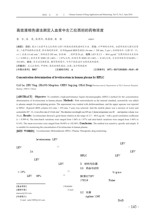
高效液相色谱法测定人血浆中左乙拉西坦的药物浓度蔡 乐,朱 英,张明华,陈静静,柴 栋(解放军总医院药学部,北京 100853)[摘要] 目的:建立人血浆中左乙拉西坦(LEV)的高效液相色谱测定方法。
方法:以甲硝唑为内标,血浆样品经乙腈沉淀蛋白,二氯甲烷提取去杂质,取水相进样分析。
采用Hypersil BDS色谱柱(4.6 mm × 250 mm,5 µm),流动相为水-乙腈(87 : 13,v/v),流速1.0 mL·min-1,检测波长205 nm,柱温40 ℃,进样量20 µL。
结果:LEV在2.5 ~ 80.0 µg·mL-1范围内线性关系良好(r = 0.999 4),批内变异(RSD)在1.06% ~ 1.97%之间,批间变异(RSD)在3.46% ~ 8.14%之间,方法学回收率为94.00% ~102.48%。
结论:本方法灵敏度高,操作简便易行,可用于临床LEV血药浓度的监测。
[关键词] 左乙拉西坦;甲硝唑;高效液相色谱法;血浆;治疗药物监测[中图分类号] R917 [文献标识码] A [文章编号] 1672 – 8157(2018)03 – 0145 – 03 Concentration determination of levetiracetam in human plasma by HPLCCAI Le, ZHU Ying, ZHANG Ming-hua, CHEN Jing-jing, CHAI Dong(Pharmaceutical Department of PLA General Hospital, Beijing 100853, China)[ABSTRACT] Objective: To establish a high-performance liquid chromatographic (HPLC) method for the concentration determination of levetiracetam in human plasma. Methods: With metronidazole as the internal standard, acetonitrile was added to plasma sample for precipitating protein. The supernatant was washed with dichloromethane, and the upper aqueous was injected to HPLC. Hypersil BDS column (4.6 mm × 250 mm, 5 µm) was selected. And the mobile phase was a mixture of water and acetonitrile (87 : 13, v/v) at a flow rate of 1.0 mL·min-1. The detection wavelength was 205 nm. Column temperature was 40 ℃ and injection volume was 20 µL. Results: Levetiracetam showed a good linear relation in the range of 2.5 – 80.0 µg·mL-1 with a good correlation coefficient (r = 0.999 4). The intra-batch variations were ranged from 1.06% to 1.97% and inter-batch variations were ranged from 3.46% to 8.14%. The mean recoveries were ranged from 94.00% to 102.48%. Conclusion: The method was sensitive, specific and simple. It is suitable for monitoring the concentration of levetiracetam in human plasma.[KEY WORDS] Levetiracetam; Metronidazole; HPLC; Plasma; Therapeutic drug monitoring左乙拉西坦(levetiracetam,LEV)是一种吡咯烷酮衍生物,其化学结构与其他抗癫痫药物无相关性。
二叠纪 三叠纪

二叠纪-三叠纪二叠纪-三叠纪灭绝事件(Permian–Triassic extinction event)是一个大规模物种灭绝事件,发生于古生代二叠纪与中生代三叠纪之间,距今大约2亿5140万年前。
[1][2]若以消失的物种来计算,当时地球上70%的陆生脊椎动物,以及高达96%的海中生物消失;[3]这次灭绝事件也造成昆虫的唯一一次大量灭绝,计有57%的科与83%的属消失。
[4][5]在灭绝事件之后,陆地与海洋的生态圈花了数百万年才完全恢复,比其他大型灭绝事件的恢复时间更长久。
[3]此次灭绝事件是地质年代的五次大型灭绝事件中,规模最庞大的一次,因此又非正式称为大灭绝(Great Dying),或是大规模灭绝之母(Mother of all mass extinctions)。
[6]二叠纪-三叠纪灭绝事件的过程与成因仍在争议中。
[7]根据不同的研究,这次灭绝事件可分为一[1]到三[8]个阶段。
第一个小型高峰可能因为环境的逐渐改变,原因可能是海平面改变、海洋缺氧、盘古大陆形成引起的干旱气候;而后来的高峰则是迅速、剧烈的,原因可能是撞击事件、火山爆发、或是海平面骤变,引起甲烷水合物的大量释放。
[9]年代测定在公元2000年之前,二叠纪与三叠纪交界的地层很少被发现,因此科学家们很难准确地估算灭绝事件的年代与经历时间,以及影响的地理范围。
[10]在1998年,科学家研究中国浙江省长兴县煤山附近的二叠纪/三叠纪岩层,他们采用铀-铅测年方法,研究锆石中的铀/铅比例,[2]估计二叠纪-三叠纪灭绝事件的发生年代为2亿5140万年前(误差值为30万年),并发现此后有随者时间持续增高的灭绝比例。
[1]在灭绝事件发生时,全球各地的碳13/碳12比例极速下降约9‰。
[11][12][13][14][15]因为二叠纪/三叠纪的界线难以用放射性定年法测定,科学家们多用急遽下降的碳13/碳12比例,测定岩层中的二叠纪/三叠纪交界。
- 1、下载文档前请自行甄别文档内容的完整性,平台不提供额外的编辑、内容补充、找答案等附加服务。
- 2、"仅部分预览"的文档,不可在线预览部分如存在完整性等问题,可反馈申请退款(可完整预览的文档不适用该条件!)。
- 3、如文档侵犯您的权益,请联系客服反馈,我们会尽快为您处理(人工客服工作时间:9:00-18:30)。
RO P RO
RO OR RO P
R N R
PAr2
O P OR O
*L1
O R1 P N 2 R O
*L2
phosphine
(膦配体)
phosphonite
(亚膦酸酯)
phosphite
(亚磷酸酯)
phosphoamidite
(亚膦酸胺酯)
磷手性中心的手性双膦配体的 问题: 1) 制备困难; 2) 较高温度下消旋。
R Me
P
P
Me R t-Bu P H P t-Bu
BisP
磷手性中心的手性双膦配体的 优点: 1)手性三烷基膦配体中有位阻 大的较稳定,不易消旋。 2)与金属生成五员环的螯合配 合物。 3)手性中心邻近反应中心。
TangPhos
过渡金属与双齿配体的八面体络合物有两种构型:和,显示出手性。
采用有C2对称轴的手性配体可减少过渡态立体构型的数目, 而有利于立体控制; 两个萘环的高度扭曲的趋向是不对称诱导的决定性因素, 同时,二面角可调节; 结构刚性,旋转位垒高,不易外消旋。形成结构明确的只具 有sp2碳原子的七员螯合环。
O O
PPh2 PPh2
DIOP
O O
PPh2 PPh2
O O
PPh2 PPh2
(S,R,R,S)
使较柔软的DIOP更刚性,引入甲基……
(S,S,S,S)
R
+ COOR" [S,S)-(EtDuPhos)Rh] H2 OR'
R
COOR" OR'
在Rh-催化的芳烯胺的氢化反应中,
(S,R,R,S)-DIOP 给出优异的对映选择性,
若加入手性二胺,会有双不对称诱导的作用
(matched 和 mismatched)。
二.用于不对称氢化反应的手性配体
2.1.手性双膦配体
(1) 联芳环类配体
A) 联二萘类双膦配体
(R)-BINAP ) BINAP (S) BINAP (S)-BINAP PPh2 PPh2 PPh2 PPh2
八面体手性
(a) 二茂铁骨架
LA
LB
O Ph N O NH O
H2 Rh-LA (0.2mol%)
O Ph H O N NH H O
Vitamin H
COOMe
H
H2 Ru-LB
COOMe H
合成香料中间体 Angew, 2001, 40, 914 JACS, 1997, 6207
(R)-, up to 99% ee
H H OPPh2 OPPh2 BICOP
SpirOP (Chan & Jiang, 1997)
合成上的困难,促进结构设计加以改进
PAr2 PAr2
R
NHCOMe
SpirOP BICOP
> 99.9% ee 94% ee
(更刚性)
(Zhou,2003)(S)-SDP
Chan, Jiang, JACS, 1997, 119, 9570
PPh2 PPh2
PPh2 PPh2
(R)-BINAP )
(S) (S)-BINAP
Ar2 P Ru(OAc)2 P Ar2
COOH Ph NHAc
L*-Rh(I), H2 Ph
COOH NHAc
O N(CH3)2 O R OH
H2
OH N(CH3)2
对双键的不对称氢化反应很有效
JACS 1980, 102, 7932
O
O
而用BINAP做催化剂,该反应仅有84%ee
4
(4) 脂肪族双膦配体 (DIOP 和 DuPhos)
(a) 酒石酸衍生双膦配体 (DIOP)
(b) DuPhos---杜邦公司 (Burk) PennPhos具有更
大的刚性和立体位 阻。手性识别能力 更强。
PennPhos
R
R P P RR
DuPhos
P
CH2*CH(Me)(Et) CH2*CH(Me)(Et)
Me *P n-Pr 28% ee
Me *P i-Pr 28% ee OMe Me *P Cy (CAMP) 88% ee
1% ee
Me *P Cy 32% ee
OMe Me *P Ph (PAMP) 58% ee
筛选手性膦配体:
磷手性中心配体有很好的不对称诱导。
L Rh L
Cl L
Rh(I) 16e
H2, -L
Oxidative addition
L H Cl Rh L H
Rh(III) 16e
L H Cl -complex Rh Rh(III), 18e L H
三.不对称氢化反应的三类底物
1.C=C 双键的不对称催化氢化反应 2.羰基化合物的不对称氢化反应 3.亚胺的不对称氢化反应
第五章 不对称氢化和还原反应
一.历史的回顾 二.用于不对称氢化反应的 手性配体
1.手性双膦配体 2.手性单膦配体 3. 手性N,P N,P-和N,N N,N-配体
一.历史的回顾
a) 1960年代前,非均相催化的不对称氢化反应 b) 1965年, 发明了可溶催化剂的均相氢化反应:Rh(PPh3)3Cl, 1973年, Wilkinson获诺贝尔化学奖
O
O O
PPh2 PPh2
Optimal Ligand
C 3-TunePhos
(d) 联吡啶类双膦配体—P-PHOS
(c) H8-BINAP
R1 MeO MeO
R2
R3 PAr2 PAr2
OMe N PAr2 PAr2 N MeO MeO N OMe P-PHOS, >99% ee (Chan, 2002) N PAr2 PAr2
Ph
螺环结构的优点: 与联二萘具有相同的C2对称性,但具有 相对高的刚性和优良的不对称性。
Xyl-SDP S/C 100,000, conv. 98%, ee 98%
Zhou, JACS, 2003, 125, 4404
(3) 平面手性双膦配体
Me
(b) PHANEPhos-Rh催化剂
PPh2 P(t-Bu)2 Fe Me Fe PCy2 P(p-C6H5CF3)2
*P
R1 R3 R2
* R1
P R3 R2
*
*P
R1 R3 R2
“双齿”配体的优越性。 取代基的适当位置有第二个配位点,对映选择性有很大提高。
d) 随后Kagan发明了双齿膦配体—DIOP
(香草醛)
DIOP-Rh(I)配合物催化-(酰氨基)丙烯酸(酯)的不对称氢 化反应 e.e.值达到80%以上。 PAMP二聚给出DIPAMP。易制备, 空气中生成稳定的晶体
More active
(S )
H2 Ar2 Ph N (S) P H Ru P Cl N (S) Ar2 H2 Ph
less active
R2 O R1 R3 R4
H2 R1
R2 OH R4 R3
特点: 适于非官能化的酮的氢化反应
对,-不饱和酮有很高的化学选择性和立体选择性。 只氢化羰基而保留双键,ee值可高达100%。 催化剂中的苯基换成大位阻基团给出更好的选择性。
95% ee
手性位于碳骨架上能与金属形成螯合配合物,发挥手性诱 导作用。---Kagan发明的意义
1
e) 1980年Noyori报道了BINAP-Rh(I)配合物催化的 不对称氢化反应
f) 1986年,使用BINAP-Ru(II)-(OAc)2又是一个重大的突破 (I)以Ru(II)/BINAP配合物作催化剂可以扩展到官能化的酮
2
B) 联二苯双膦配体 联二芳环的二面角(dihedral angle)对对映选择性有很大的影响!! (X. Zhang, “New Chiral Phosphorus Ligands for Enantioselective Hydrogenation”, Chem. Rev. 2003, 103, 3029)
PPh2 PPh2
R1
R2
R3
吡啶基团的氮原子也能参加配位,使中心金属的配位达到饱和,降低 了活性。周围引入一定体积的取代基后可防止氮原 子与催化剂中金属
BINAP经还原有一个苯环成脂肪环,改变了二面角, 在 Ru- 催 化 的 不 饱 和 羧 酸 的 氢 化 应 中 H8-BINAP 比 BINAP表现出更好的对映选择性。
H- transfer
RhClL3 + CH3CH3
四. 除氢化反应外的还原体系
+L Reductive elimination
L H Cl -complex Rh(III), 16e Rh L CH2CH3
c) 1968年,Knowles以手性膦配体代替三苯基膦 以-(酰氨基)丙烯酸(酯)的不对称氢化反应为模型反应
原子的配位,增加催化剂的活性。 Ar改用大位阻基团,选择性更好 适用于各种不同的底物 催化剂对空气和水不敏感,甚至可用水处理。可大规模制备
Chan, A. S. C.,JACS,2000,11513
3
(2) 螺环双膦配体
* R * Spiro[4,4]-nonane Ph2P * O O * *
O (CH2)n O
n = 1~6
PPh2 PPh2
Dihedral Angle (°) Substrate
O N O
Compare E.e.(%)
91 3 90.3 91.3 90 3 98.5 98 5 95.1 95 1 95.3 95 3 90.7 90 7
96 1 96.1
94 3 94.3
R=P (?)