电气相关外文翻译---CAN 协议
电气工程及其自动化专业_外文文献_英文文献_外文翻译_plc方面.
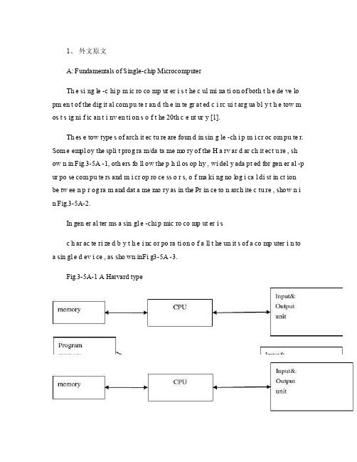
1、外文原文A: Fundamentals of Single-chip MicrocomputerTh e si ng le -c hi p m ic ro co mp ut er i s t he c ul mi na ti on of both t h e de ve lo pm en t of the dig it al com pu te r an d th e in te gr at ed c i rc ui t arg ua bl y t h e tow m os t s ig ni f ic an t i nv en ti on s o f t he 20th c e nt ur y [1].Th es e tow type s of arch it ec tu re are foun d in sin g le -ch i p m i cr oc om pu te r. Som e empl oy the spli t prog ra m/da ta me mo ry of the H a rv ar d ar ch it ect u re , sh ow n in Fig.3-5A -1, oth ers fo ll ow the p h il os op hy , wi del y ada pt ed for gen er al -p ur po se com pu te rs and m i cr op ro ce ss o r s, o f ma ki ng no log i ca l di st in ct ion be tw ee n p r og ra m and dat a me mo ry as in the Pr in ce to n arch ite c tu re , show n i n Fig.3-5A-2.In gen er al ter ms a sin gl e -chi p mic ro co mp ut er i sc h ar ac te ri zed b y t he i nc or po ra ti on of a ll t he un it s of a co mp uter i n to a sin gl e d ev i ce , as sho wn inFi g3-5A -3.Fig.3-5A-1 A Harvard typeFig.3-5A-2. A conventional Princeton computerFig3-5A-3. Principal features of a microcomputerRead only memory (ROM.R OM is usua ll y for the pe rm an ent,n o n-vo la ti le stor a ge of an app lic a ti on s pr og ra m .M an ym i cr oc om pu te rs and m are inte nd e d for high -v ol um e ap pl ic at ions a n d he nc e t h e eco n om ic al man uf act u re of th e de vic e s re qu ir es t h at t he cont en t s o f t he prog ra m me m or y be co mm it t ed perm a ne ntly d u ri ng the man ufa c tu re of ch ip s .Cl ea rl y, thi s im pl ie s a r i go ro us app ro ach to ROM cod e deve l op me nt sin ce cha ng es can not b e mad e afte r manu f a c tu re .Th is dev e lo pm en t proc ess may invo lv e e m ul at io n us in g aso ph is ti ca te d de ve lo pm en t sy ste m wit h a h a rd wa re emu la tio n cap ab il it y as w el l as the use o f po we rf ul s o ft wa re too ls.So me man uf act u re rs pro vi de add it io na l RO M opt i on s by i n cl ud in g in their ra n ge dev ic es wit h (or int en de d fo r use wit h u s er pro gr am ma ble me mo ry. Th e sim p le st of th es e is usu al ly d e vi ce whi ch can op er at e in a micro p ro ce ssor mod e by usi ng som e o f the inp ut /outp u t li ne s as an ad dr es s an d da ta b us fora c ce ss in g ex te rna l mem or y. Thi s t y pe of de vi ce can beh av ef u nc ti on al ly as th e sing le chip mi cr oc om pu te r from whi ch it is d e ri ve d al be it wit h re st ri ct ed I/O and a mod if ied ex te rn al c i rc ui t. The use of thes e d ev ic es is com mo n eve n in prod uc ti on c i rc ui ts wher e t he vo lu me does no tj us ti f y t h e d ev el o pm en t c osts o f c us to m o n -ch i p R OM [2];t he re c a n s ti ll bea s ignif i ca nt saving i n I /O and o th er c h ip s com pa re d to a conv en ti on al mi c ro pr oc es sor b a se d ci rc ui t. Mor e ex ac t re pl ace m en t fo r RO M dev i ce s ca n be o b ta in ed in th e fo rm of va ri an ts w it h 'p ig gy -b ack 'E P RO M(Er as ab le pro gr am ma bl e ROM s oc ke ts or dev ic e s with EPROM i n st ea d o f RO M 。
CAN总线协议

CAN总线协议协议名称:Controller Area Network (CAN) 总线协议协议概述:CAN总线协议是一种用于在电气控制单元(ECU)之间进行高速通信的网络协议。
它最初由Bosch公司开发,用于汽车领域,但现在已广泛应用于其他领域,如工业自动化和医疗设备等。
CAN总线协议具有高可靠性、实时性和容错性的特点,适用于多节点通信和分布式控制系统。
协议内容:1. 物理层CAN总线协议使用双绞线作为传输介质,并采用差分信号传输。
传输速率可根据需求选择,常见的速率有1 Mbps、500 kbps和250 kbps等。
总线长度和拓扑结构应根据具体应用进行规划。
2. 数据链路层2.1 帧格式CAN总线协议使用帧格式来传输数据。
帧由以下几个字段组成:- 起始位(SOF):标识帧的开始。
- 标识符(ID):用于识别不同的消息。
- 控制位(RTR):用于指示数据帧还是远程帧。
- 数据长度码(DLC):指示数据字段的长度。
- 数据字段(Data):存储实际数据。
- CRC:用于检测传输错误。
- 确认位(ACK):用于确认数据帧是否被接收。
- 结束位(EOF):标识帧的结束。
2.2 帧类型CAN总线协议定义了两种帧类型:- 数据帧:用于传输实际数据。
- 远程帧:用于请求其他节点发送数据。
2.3 错误检测和恢复CAN总线协议具有强大的错误检测和恢复机制。
每个节点在发送数据时都会对其进行CRC校验,接收节点也会进行CRC校验来检测传输错误。
如果检测到错误,节点可以通过重新发送数据来进行恢复。
3. 网络层CAN总线协议使用基于优先级的非冲突访问机制。
每个消息都有一个唯一的标识符,具有较低标识符的消息具有较高的优先级。
当多个节点同时发送消息时,具有较高优先级的消息会被优先发送。
4. 应用层CAN总线协议的应用层可以根据具体需求进行定制。
常见的应用包括以下几个方面:- 传感器数据传输:CAN总线协议可以用于传输各种传感器数据,如温度、压力和位置等。
can协议完全讲解

can协议完全讲解CAN协议完全讲解。
CAN协议是Controller Area Network的缩写,是一种串行通信协议,广泛应用于汽车、工业控制、航空航天等领域。
CAN协议的特点是高可靠性、实时性强、抗干扰能力强,因此在工业控制领域得到了广泛的应用。
首先,CAN协议的基本原理是基于总线的通信方式,即多个节点通过共享同一条总线进行通信。
CAN总线上的每个节点都有一个唯一的标识符,可以通过这个标识符来识别节点。
当一个节点发送消息时,其他节点可以根据消息的标识符来判断是否需要接收这个消息。
这种方式可以有效地减少通信冲突,提高通信效率。
其次,CAN协议采用了差分信号传输的方式,可以有效地抵抗电磁干扰。
在传输过程中,CAN总线上的信号由两个相互反向的差分信号组成,这样可以使得信号在传输过程中对干扰的抵抗能力更强。
因此,CAN总线可以在恶劣的工作环境下稳定地工作,保证通信的可靠性。
另外,CAN协议还具有较高的实时性。
CAN总线上的消息可以根据优先级来进行传输,优先级高的消息可以在总线空闲时立即发送,从而保证了消息的实时性。
这对于一些对通信时延要求较高的应用场景非常重要,比如汽车电子控制系统、工业自动化控制系统等。
此外,CAN协议还支持多主机系统,多个节点可以同时发送消息,而且不会发生冲突。
CAN协议采用了非破坏性位冲突检测和重发机制,可以确保消息的可靠传输。
这对于需要多个节点同时进行通信的系统来说非常重要。
总的来说,CAN协议作为一种高可靠性、实时性强、抗干扰能力强的串行通信协议,在汽车、工业控制、航空航天等领域得到了广泛的应用。
它的基本原理是基于总线的通信方式,采用了差分信号传输的方式,具有较高的实时性和支持多主机系统的特点。
希望本文对CAN协议有所了解,对相关领域的从业者有所帮助。
CAN总线协议

CAN总线协议协议名称:CAN总线协议一、引言CAN总线协议是一种广泛应用于汽车、工业控制、航空航天等领域的通信协议。
本协议旨在规范CAN总线通信的物理层和数据链路层,确保数据的可靠传输和系统的稳定性。
二、术语和缩略语2.1 术语- CAN(Controller Area Network):控制器局域网,指一种串行通信总线。
- CAN节点:连接在CAN总线上的设备或系统。
- 帧(Frame):CAN总线上的数据传输单位,包括数据和控制信息。
- 数据域(Data Field):帧中用于传输数据的部分。
- 标识符(Identifier):用于唯一标识CAN帧的字段。
- 帧格式(Frame Format):CAN帧的结构和格式。
- 位定时器(Bit Timing):用于控制CAN总线上的位传输速率的定时器。
2.2 缩略语- DLC(Data Length Code):数据长度码,用于指示数据域的字节数。
- ACK(Acknowledge):确认信号,用于指示数据是否被接收。
- CRC(Cyclic Redundancy Check):循环冗余校验,用于检测数据传输中的错误。
- Baud Rate:波特率,用于表示CAN总线上的数据传输速率。
三、物理层规范3.1 传输介质CAN总线协议可以使用双绞线、光纤等传输介质,具体选择应根据系统需求和环境条件进行合理选择。
3.2 电气特性CAN总线协议采用差分信号传输方式,传输线上的电压差应符合以下规范:- 高电平:+2.5V至+5V- 低电平:-2.5V至-5V传输线上的电压差应保持在2V以上,以确保信号的可靠传输。
3.3 位定时器设置CAN总线协议的位定时器应根据系统需求进行合理设置,以确保数据的稳定传输。
位定时器的参数包括以下内容:- 传输速率:根据系统需求设置波特率,常见的波特率有125Kbps、250Kbps、500Kbps和1Mbps等。
- 采样点设置:设置采样点的位置,常见的设置为87.5%。
电气工程及其自动化专业外文文献英文文献外文翻译方面
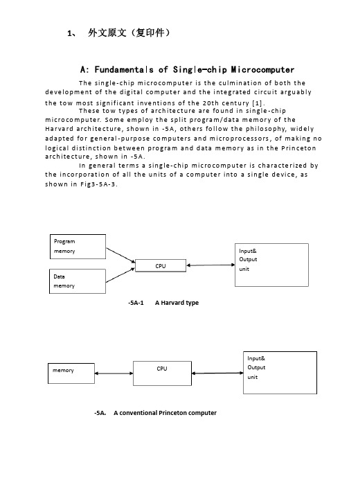
1、 外文原文(复印件)A: Fundamentals of Single-chip MicrocomputerT h e sin gle -ch ip mi c ro co m p u t e r is t h e cu lm in at io n of b ot h t h e d e ve lo p me nt of t h e d ig ita l co m p u t e r a n d t h e i nte g rated c ircu it a rgu ab l y t h e to w mo st s ign if i cant i nve nt i o n s of t h e 20t h c e nt u ry [1].T h ese to w t yp e s of arch ite ct u re are fo u n d in s in gle -ch ip m i cro co m p u te r. S o m e e mp l oy t h e sp l it p ro gra m /d at a m e m o r y of t h e H a r va rd arch ite ct u re , s h o wn in -5A , ot h e rs fo l lo w t h e p h i lo so p hy, wid e l y ad a p ted fo r ge n e ral -p u rp o se co m p u te rs an d m i cro p ro ce ss o rs , of m a kin g n o l o g i ca l d i st in ct i o n b et we e n p ro gra m an d d ata m e m o r y as in t h e P rin c eto n a rch ite ct u re , sh o wn in -5A.In ge n e ra l te r m s a s in g le -ch ip m ic ro co m p u t e r is ch a ra cte r ized b y t h e in co r p o rat io n of all t h e u n its of a co mp u te r into a s in gle d e vi ce , as s h o w n in F i g3-5A-3.-5A-1A Harvard type-5A. A conventional Princeton computerProgrammemory Datamemory CPU Input& Output unitmemoryCPU Input& Output unitResetInterruptsPowerFig3-5A-3. Principal features of a microcomputerRead only memory (ROM).RO M is u su a l l y fo r t h e p e r m an e nt , n o n -vo lat i le sto rage of an ap p l i cat io n s p ro g ram .M a ny m i c ro co m p u te rs a n d m i cro co nt ro l le rs are inte n d ed fo r h i gh -vo lu m e ap p l i cat io n s a n d h e n ce t h e e co n o m i cal man u fa c t u re of t h e d e vi ces re q u ires t h at t h e co nt e nts of t h e p ro gra m me mo r y b e co mm i ed p e r m a n e nt l y d u r in g t h e m a n u fa ct u re of c h ip s . C lea rl y, t h i s imp l ies a r i go ro u s ap p ro a ch to ROM co d e d e ve lo p m e nt s in ce ch an ges can n o t b e mad e af te r m an u fa ct u re .T h i s d e ve l o p m e nt p ro ces s m ay i nvo l ve e mu l at i o n u sin g a so p h ist icated d e ve lo p m e nt syste m wit h a h ard wa re e mu l at i o n capab i l it y as we ll as t h e u s e of p o we rf u l sof t war e to o l s.So m e m an u fa ct u re rs p ro vi d e ad d it i o n a l ROM o p t io n s b y in clu d in g in t h e i r ran ge d e v ic es w it h (o r inte n d ed fo r u s e wit h ) u se r p ro g ram m a b le m e mo r y. T h e s im p lest of t h e se i s u su a l l y d e v i ce wh i ch can o p e rat e in a m i cro p ro ce s so r mo d e b y u s in g s o m e of t h e in p u t /o u t p u t l in es as an ad d res s a n d d ata b u s fo r a cc es sin g exte rn a l m e m o r y. T h is t yp e o f d e vi ce can b e h ave f u n ct i o n al l y as t h e s in gle ch ip m i cro co m p u t e r f ro m wh i ch it i s d e ri ved a lb e it wit h re st r icted I/O an d a m o d if ied exte rn a l c ircu it. T h e u s e of t h e se RO M le ss d e vi ces i s co mmo n e ve n in p ro d u ct io n circu i ts wh e re t h e vo lu m e d o e s n ot ju st if y t h e d e ve lo p m e nt co sts of cu sto m o n -ch ip ROM [2];t h e re ca n st i ll b e a si gn if i cant sav in g in I/O an d o t h e r ch ip s co m pared to a External Timing components System clock Timer/ Counter Serial I/O Prarallel I/O RAM ROMCPUco nve nt io n al m i c ro p ro ces so r b ased circ u it. M o re exa ct re p l a ce m e nt fo rRO M d e v ice s can b e o b tain ed in t h e fo rm of va ria nts w it h 'p i g g y-b a c k'E P ROM(E rasab le p ro gramm ab le ROM )s o cket s o r d e v ice s w it h E P ROMin stead of ROM 。
CAN总线协议

CAN总线协议协议名称:CAN总线协议一、引言CAN(Controller Area Network)总线协议是一种广泛应用于汽车和工业控制领域的串行通信协议。
该协议采用多主从架构,具有高可靠性、高带宽、抗干扰能力强等特点。
本协议旨在规范CAN总线的通信方式、帧格式、物理层特性以及错误处理等方面的内容。
二、范围本协议适用于CAN总线的设计、开发和应用过程中的通信协议规范。
三、术语和定义1. CAN总线:一种串行通信总线,用于连接多个节点进行数据传输。
2. 节点:连接到CAN总线的设备或系统。
3. 帧:CAN总线上的数据传输单位,包括数据域、标识符、控制位等。
4. 标识符:用于标识CAN帧的唯一ID。
5. 数据域:CAN帧中用于传输数据的部分。
6. 帧格式:CAN帧的结构和编码方式。
7. 物理层:CAN总线的硬件接口和电气特性。
四、通信方式1. 通信速率:CAN总线支持多种通信速率,包括1Mbps、500kbps、250kbps 等,根据实际需求进行选择。
2. 帧类型:CAN总线支持标准帧和扩展帧两种类型。
标准帧使用11位标识符,扩展帧使用29位标识符。
3. 帧发送:节点可以通过发送数据帧、远程帧和错误帧等方式进行通信。
4. 帧接收:节点可以通过接收数据帧和远程帧等方式进行通信。
五、帧格式1. 标准帧格式:- 11位标识符:用于标识CAN帧的唯一ID。
- RTR位:远程传输请求位,用于区分数据帧和远程帧。
- IDE位:帧扩展位,用于区分标准帧和扩展帧。
- 控制位:用于控制CAN帧的发送和接收。
- 数据域:用于传输数据的部分,最多可以包含8个字节的数据。
2. 扩展帧格式:- 29位标识符:用于标识CAN帧的唯一ID。
- RTR位:远程传输请求位,用于区分数据帧和远程帧。
- IDE位:帧扩展位,用于区分标准帧和扩展帧。
- 控制位:用于控制CAN帧的发送和接收。
- 数据域:用于传输数据的部分,最多可以包含8个字节的数据。
CAN通讯协议

CAN通讯协议协议名称:CAN通讯协议一、引言CAN(Controller Area Network)通讯协议是一种广泛应用于汽车、工业控制和其他领域的串行通信协议。
该协议基于事件驱动的通信机制,具有高效、可靠和实时性的特点。
本协议旨在规范CAN通讯协议的标准格式,以确保不同设备之间的互操作性和数据传输的准确性。
二、术语和定义1. CAN总线:指用于连接CAN节点的传输介质,通常为双绞线。
2. CAN节点:指连接到CAN总线上的设备或系统。
3. 帧(Frame):指CAN通讯中的数据单元,包含标识符、数据、控制位等信息。
4. 标识符(Identifier):用于定义CAN帧的类型和优先级。
5. 数据(Data):指CAN帧中传输的实际信息。
6. 控制位(Control Bits):用于指示CAN帧的状态和控制信息。
三、协议规范1. CAN帧格式CAN帧由标识符、数据、控制位等组成,其格式如下:- 标准帧(Standard Frame):11位标识符+0-8字节数据。
- 扩展帧(Extended Frame):29位标识符+0-8字节数据。
- 远程帧(Remote Frame):11位或29位标识符,用于请求数据而不包含实际数据。
2. 标识符- 标准标识符:11位二进制数,用于定义CAN帧的类型和优先级。
- 扩展标识符:29位二进制数,用于定义CAN帧的类型和优先级。
3. 数据传输- 数据长度:CAN帧中数据长度可变,最多可传输8字节的数据。
- 数据传输方式:CAN通讯采用异步传输方式,节点之间通过CAN总线进行数据交换。
- 数据传输速率:CAN总线的数据传输速率可根据系统需求进行调整,常见的速率有125kbps、250kbps、500kbps和1Mbps等。
4. 错误检测- 奇偶校验:CAN帧中的标识符和数据采用奇偶校验,以确保数据的完整性。
- 位错误检测:CAN帧中的控制位包含了位错误检测的信息,用于检测传输过程中的错误。
CAN 协议外文文献翻译、中英文翻译、外文翻译

CAN protocolM .J .SchofieldThe CAN protocol is an international standard defined in the ISO 11898. Beside the CAN protocol itself the conformance test for the CAN protocol is defined in the ISO 16845, which guarantees the interchangeability of the CAN chips.1. Principles of data exchangeCAN is based on the “broadcast communication mechanism”, which is based on a message-oriented transmission protocol. It defines message contents rather than stations and station addresses. Every message has a message identifier, which is unique within the whole network since it defines content and also the priority of the message. This is important when several stations compete for bus access (bus arbitration).As a result of the content-oriented addressing scheme a high degree of system and configuration flexibility is achieved. It is easy to add stations to an existing CAN network without making any hardware or software modifications to the present stations as long as the new stations are purely receivers. This allows for a modular concept and also permits the reception of multiple data and the synchronization of distributed processes. Also, data transmission is not based on the availability of specific types of stations, which allows simple servicing and upgrading of the network.2. Real-time data transmissionIn real-time processing the urgency of messages to be exchanged over the network can differ greatly: a rapidly changing dimension, e.g. engine load, has to be transmitted more frequently and therefore with less delays than other dimensions, e.g. engine temperature.The priority, at which a message is transmitted compared to another less urgent message, is specified by the identifier of each message. The priorities are laid down during system design in the form of corresponding binary values and cannot be changed dynamically. The identifier with the lowest binary number has the highest priority.Bus access conflicts are resolved by bit-wise arbitration of the identifiers involved by each station observing the bus level bit for bit. This happens in accordance with the wired-and-mechanism, by which the dominant state overwrites the recessive state. All those stations (nodes) with recessive transmission and dominant observation lose the competition for bus access. All those "losers" automatically become receivers of the message with the highest priority and do not re-attempt transmission until the bus is available again.Transmission requests are handled in order of their importance for the system as a whole. This proves especially advantageous in overload situations.Since bus access is prioritized on the basis of the messages, it is possible to guarantee low individual latency times in real-time systems.3. Message frame formatsThe CAN protocol supports two message frame formats, the only essential difference being in the length of the identifier. The “CAN base frame” supports a length of 11 bits for the identifier, and the “CAN extended frame” supports a length of 29 bits for the identifier.4. CAN extended frame formatThe difference between an extended frame format message and a base frame format message is the length of the identifier used. The 29-bit identifier is made up of the 11-bit identifier (“base identifier”) and an 18-bit extension (“identifier extension”). The distinction between CAN base frame format and CAN extended frame format is made by using the IDE bit, which is transmitted as dominant in case of an 11-bit frame, and transmitted as recessive in case of a 29-bit frame. As the two formats have to co-exist on one bus, it is laid down which message has higher priority on the bus in the case of bus access collision with different formats and the same identifier / base identifier: The 11-bitmessage always has priority over the 29-bit message.The extended format has some trade-offs: The bus latency time is longer (in minimum 20 bit-times), messages in extended format require more bandwidth (about 20 %), and the error detection performance is lower (because the chosen polynomial for the 15-bit CRC is optimized for frame length up to 112 bits).CAN controllers, which support extended frame format messages are also able to send and receive messages in CAN base frame format. CAN controllers that just cover the base frame format do not interpret extended frames correctly. However there are CAN controllers, which only support the base frame format but recognize extended messages and ignore them.5. Detecting and signaling errorsUnlike other bus systems, the CAN protocol does not use acknowledgement messages but instead signals errors immediately as they occur. For error detection the CAN protocol implements three mechanisms at the message level (data link layer: OSI layer 2):∙Cyclic Redundancy Check (CRC): The CRC safeguards the information in the frame by adding a frame check sequence (FCS) at the transmissionend. At the receiver this FCS is re-computed and tested against thereceived FCS. If they do not match, there has been a CRC error.∙Frame check: This mechanism verifies the structure of the transmitted frame by checking the bit fields against the fixed format and the framesize. Errors detected by frame checks are designated "format errors".∙ACK errors: Receivers of a message acknowledge the received frames. If the transmitter does not receive an acknowledgement an ACK error isindicated.The CAN protocol also implements two mechanisms for error detection at the bit level (physical layer: OSI layer 1):∙Monitoring: The ability of the transmitter to detect errors is based on the monitoring of bus signals. Each station that transmits also observes thebus level and thus detects differences between the bit sent and the bitreceived. This permits reliable detection of global errors and errors localto the transmitter.∙Bit stuffing: The coding of the individual bits is tested at bit level. The bit representation used by CAN is "Non Return to Zero (NRZ)" coding.The synchronization edges are generated by means of bit stuffing. Thatmeans after five consecutive equal bits the transmitter inserts a stuff bitinto the bit stream. This stuff bit has a complementary value, which isremoved by the receivers.If one or more errors are discovered by at least one station using the above mechanisms, the current transmission is aborted by sending an "error frame". This prevents other stations from accepting the message and thus ensures the consistency of data throughout the network. After transmission of an erroneous message that has been aborted, the sender automatically re-attempts transmission (automatic re-transmission). Nodes may again compete for bus access.However effective and efficient the method described may be, in the event of a defective station it might lead to all messages (including correct ones) being aborted. If no measures for self-monitoring were taken, the bus system would be blocked by this. The CAN protocol therefore provides a mechanism to distinguish sporadic errors from permanent errors and local failures at the station. This is done by statistical assessment of station error situations with the aim of recognizing a station's own defects and possibly entering an operation mode in which the rest of the CAN network is not negatively affected. This may continue as far as the station switching itself off to prevent other nodes' messages erroneously from being recognized as incorrect.CAN 协议斯科菲尔德CAN协议是在ISO 11898中定义的国际标准。
- 1、下载文档前请自行甄别文档内容的完整性,平台不提供额外的编辑、内容补充、找答案等附加服务。
- 2、"仅部分预览"的文档,不可在线预览部分如存在完整性等问题,可反馈申请退款(可完整预览的文档不适用该条件!)。
- 3、如文档侵犯您的权益,请联系客服反馈,我们会尽快为您处理(人工客服工作时间:9:00-18:30)。
中文1960字附录二文献翻译CAN protocolM .J .SchofieldThe CAN protocol is an international standard defined in the ISO 11898. Beside the CAN protocol itself the conformance test for the CAN protocol is defined in the ISO 16845, which guarantees the interchangeability of the CAN chips.1. Principles of data exchangeCAN is based on the “broadcast communication mechanism”, which is based on a message-oriented transmission protocol. It defines message contents rather than stations and station addresses. Every message has a message identifier, which is unique within the whole network since it defines content and also the priority of the message. This is important when several stations compete for bus access (bus arbitration).As a result of the content-oriented addressing scheme a high degree of system and configuration flexibility is achieved. It is easy to add stations to an existing CAN network without making any hardware or software modifications to the present stations as long as the new stations are purely receivers. This allows for a modular concept and also permits the reception of multiple data and the synchronization of distributed processes. Also, data transmission is not based on the availability of specific types of stations, which allows simple servicing and upgrading of thenetwork.2. Real-time data transmissionIn real-time processing the urgency of messages to be exchanged over the network can differ greatly: a rapidly changing dimension, e.g. engine load, has to be transmitted more frequently and therefore with less delays than other dimensions, e.g. engine temperature.The priority, at which a message is transmitted compared to another less urgent message, is specified by the identifier of each message. The priorities are laid down during system design in the form of corresponding binary values and cannot be changed dynamically. The identifier with the lowest binary number has the highest priority.Bus access conflicts are resolved by bit-wise arbitration of the identifiers involved by each station observing the bus level bit for bit. This happens in accordance with the wired-and-mechanism, by which the dominant state overwrites the recessive state. All those stations (nodes) with recessive transmission and dominant observation lose the competition for bus access. All those "losers" automatically become receivers of the message with the highest priority and do not re-attempt transmission until the bus is available again.Transmission requests are handled in order of their importance for the system as a whole. This proves especially advantageous in overload situations. Since bus access is prioritized on the basis of the messages, it is possible to guarantee low individuallatency times in real-time systems.3. Message frame formatsThe CAN protocol supports two message frame formats, the only essential difference being in the length of the identifier. The “CAN base frame” supports a length of 11 bits for the identifier, and the “CAN extended frame” supports a length of 29 bits for the identifier.4. CAN extended frame formatThe difference between an extended frame format message and a base frame format message is the length of the identifier used. The 29-bit identifier is made up of the 11-bit identifier (“base identifier”) and an 18-bit extension (“identifier extension”). The distinction between CAN base frame format and CAN extended frame format is made by using the IDE bit, which is transmitted as dominant in case of an 11-bit frame, and transmitted as recessive in case of a 29-bit frame. As the two formats have to co-exist on one bus, it is laid down which message has higher priority on the bus in the case of bus access collision with different formats and the same identifier / base identifier: The 11-bit message always has priority over the 29-bit message.The extended format has some trade-offs: The bus latency time is longer (in minimum 20 bit-times), messages in extended format require more bandwidth (about 20 %), and the error detection performance is lower (because the chosen polynomialfor the 15-bit CRC is optimized for frame length up to 112 bits).CAN controllers, which support extended frame format messages are also able to send and receive messages in CAN base frame format. CAN controllers that just cover the base frame format do not interpret extended frames correctly. However there are CAN controllers, which only support the base frame format but recognize extended messages and ignore them.5. Detecting and signaling errorsUnlike other bus systems, the CAN protocol does not use acknowledgement messages but instead signals errors immediately as they occur. For error detection the CAN protocol implements three mechanisms at the message level (data link layer: OSI layer 2):∙Cyclic Redundancy Check (CRC): The CRC safeguards the information in the frame by adding a frame check sequence (FCS) at the transmission end. At the receiver this FCS is re-computed and tested against the received FCS. If theydo not match, there has been a CRC error.∙Frame check: This mechanism verifies the structure of the transmitted frame by checking the bit fields against the fixed format and the frame size. Errorsdetected by frame checks are designated "format errors".∙ACK errors: Receivers of a message acknowledge the received frames. If the transmitter does not receive an acknowledgement an ACK error is indicated.The CAN protocol also implements two mechanisms for error detection at the bit level (physical layer: OSI layer 1):∙Monitoring: The ability of the transmitter to detect errors is based on the monitoring of bus signals. Each station that transmits also observes the buslevel and thus detects differences between the bit sent and the bit received.This permits reliable detection of global errors and errors local to thetransmitter.Bit stuffing: The coding of the individual bits is tested at bit level. The bit representation used by CAN is "Non Return to Zero (NRZ)" coding. Thesynchronization edges are generated by means of bit stuffing. That means after five consecutive equal bits the transmitter inserts a stuff bit into the bit stream.This stuff bit has a complementary value, which is removed by the receivers.If one or more errors are discovered by at least one station using the above mechanisms, the current transmission is aborted by sending an "error frame". This prevents other stations from accepting the message and thus ensures the consistency of data throughout the network. After transmission of an erroneous message that has been aborted, the sender automatically re-attempts transmission (automatic re-transmission). Nodes may again compete for bus access.However effective and efficient the method described may be, in the event of a defective station it might lead to all messages (including correct ones) being aborted. If no measures for self-monitoring were taken, the bus system would be blocked by this. The CAN protocol therefore provides a mechanism to distinguish sporadic errors from permanent errors and local failures at the station. This is done by statistical assessment of station error situations with the aim of recognizing a station's own defects and possibly entering an operation mode in which the rest of the CAN network is not negatively affected. This may continue as far as the station switching itself off to prevent other nodes' messages erroneously from being recognized as incorrect.CAN 协议斯科菲尔德CAN协议是在ISO 11898中定义的国际标准。