ga 10b空气泵说明书
塔克泵气压器产品目录说明书
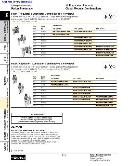
Catalog PDN1000-2USParker PneumaticFilter + Regulator + Lubricator Combinations + Poly Bowl5 micron element, 8 bar (116 PSIG) Regulator + Gauge and Wall Mounting BracketsInlet pressure 10 bar (145 PSIG), Secondary pressure 6.3 bar (91.3 PSIG), 1 bar (14.5 PSIG) pressure drop.Port size Drain type Part number P31 SeriesP32 SeriesP33 SeriesFilter / Regulator + Lubricator Combinations + Poly Bowl5 micron element, 8 bar (116 PSIG) Regulator + Gauge and Wall Mounting Brackets Inlet pressure 10 bar (145 PSIG), Secondary pressure 6.3 bar (91.3 PSIG), 1 bar (14.5 PSIG) pressure drop.Port size Drain type Part number P31 SeriesP32 SeriesP33 SeriesAir Preparation ProductsGlobal Modular CombinationsMost popular.! WARNINGProduct rupture can cause serious injury.Do not connect regulator to bottled gas.Do not exceed maximum primary pressure rating.CAUTION:REGULATOR PRESSURE ADJUSTMENT –The working range of knob adjustment is designed to permit outlet pressures within their full range. Pressure adjustment beyond this range is also possible because the knob is not a limiting device. This is a common characteristic of most industrial regulators, and limiting devices may be obtained only by special design.For best performance, regulated pressure should always be set by increasing the pressure up to the desired setting.Click here to view bookmarks.Catalog PDN1000-2USParker PneumaticAir Preparation ProductsGlobal Modular CombinationsOrdering information(Revised 8-5-2013)Catalog PDN1000-2US Parker PneumaticAir Preparation Products Global Modular CombinationsP31CP32C P33CI.D. TI.D. T。
ga 10b空气泵说明书
ga 10b空气泵说明书一.正确的充气过程:1.确保所充气瓶的检验日期在规定的检验日期内,检查气瓶的外观情况,无任何的损伤现象。
检查气瓶阀,压力表。
无任何的损伤迹象。
2.检查空气压缩机的操作维护记录,确保压缩机得滤芯,润滑油在允许的使用时间内,确保压缩机五任何故障,按制造商提供的使用说明书正确使用压缩机。
3.气瓶第一次充气时,气瓶内无压力,不要一次充气到最高压力,一般先充气致15Ma~17Ma,取下冷却10~15分钟后再充。
这点对于国内制造的空气压缩机尤其重要。
4.如使用防爆充气柜且充气柜带水槽的话,请尽量使用这种设备且带冷却水,这种充气设备冷却效果最好,如使用此设备,充气过程可一次完成。
5.充气过程中操作人员不得离开操作现场,要时常注意充气压力,压力表和瓶阀的温度,特别是要注意不得“过压”充气。
6.如果使用的是国产的充气泵,要特别注意充气温度。
充气温度直接会影响到压力表,瓶阀。
7.严格按制造商的使用说明操作压缩机:对于每分钟100升的小型压缩机,每隔15分钟一定要放水、排污一次,每充5瓶后一定要让压缩机“休息”10分钟,以确保压缩机处于最佳的工作状态并延长压缩机的使用寿命。
按使用说明书的规定更换滤芯和润滑油。
8.气瓶和压缩机的连接只能用手工完成,不得使用工具强行操作。
9.气瓶的打开和关闭不得使用太大的力矩,尤其要克服这样的心理:好象气瓶里面的30Ma的压力,非得要用很大的力矩关瓶,关闭瓶阀时不需使用大力矩,只要将气瓶关紧即可。
10.在有良好通风的环境中使用压缩机,使用时避免汽车尾气,不得在操作现场抽烟。
11.充气及使用压缩机要经过培训合格后的人才能进行此项工作。
登高水泵GA101说明书
登高水泵GA101说明书
打开风门以及进油开关,油门加到一半进行启动,启动后3到5分钟后可以根据需要进行调节油门大小,以及加压器,已达到最佳使用状态,(加压过程中不要将水枪完全不出水状态,必须在半开状态下,以免胀管损机)。
使用中经常观察水箱水量以及油料是否充足,及时补充(油料补充时必须停机,停机前必须通知前方水枪使用人员)。
使用完毕后,用相反的方法将机器停机,停机前(恢复启动状态下空转30到60秒)已便于下次更好的启动,以及延长机器的使用寿命。
空气充气泵操作规程
空气充气泵操作规程空气填充泵作业指导卡一、准备工作1、检查空气填充装运行环境是否在通风区域,安装要平稳;2、检查空气填充泵的电源连接,同时要有可靠的接地保护;3、检查保护罩是否完整、充气管及其它设备组件是否完好;二、操作要求1、严格执行本操作规程;2、启动后必须两人以上专人全程现场操作并监测设备的工作运行状况;3、启动后用纸条检查电机的旋转方向与填充泵工作方向是否一致。
三、填充操作1、检查润滑油:a. 启动填充泵之前检查润滑油,液面在标尺的上下标线之间。
b. 将分离器排污阀和充气管泄压阀打开,合上电源开关,填充泵运转1-2分钟使其充分润滑。
c. 检查充气管接头、密封圈完好。
2、检查安全阀设定压力:当填充泵第一次填充气瓶或者长期存放再启用时要检查安全阀设定压力值。
3、填充气瓶:a. 按上述方法步骤检查过润滑油、安全阀后停机,关闭分离器排污阀和充气管泄压阀,连接充气瓶,打开气瓶瓶阀,重新启动,填充开始。
b. 充压完毕后,关闭气瓶瓶阀,打开充气管泄压阀,当压力表指示为零后,方可以从充气管上摘下气瓶,关闭充气管泄压阀;c. 需要继续填充时连接气瓶,重复3-a填充气瓶,不再填充时,待1-2分钟填充泵降温后关闭电源开关,填充工作结束。
四、注意事项1、润滑油要使用专用机油并且每次启动前必须检查油位,油面高时会增加分离器排污量,或造成填充泵停机;油面低时会造成设备损坏。
2、排污阀排污时间根据环境湿度和润滑油量而定,一般10-30分钟一次。
3、使用后关闭电源、待填充泵冷却后擦净油污,关闭分离器排污阀。
长时间放置3个月运行一次,一年更换一次机油。
真空压缩袋电动气泵的使用方法
真空压缩袋电动气泵的使用方法
随着人们对家居环境的要求越来越高,真空压缩袋越来越受到大家的喜爱。
在压缩前,我们需要将里面的空气排出来,这对于我们来说是一件比较费力的事情。
但是电动气泵却可以轻松解决这一难题。
下面我们来一起了解一下真空压缩袋电动气泵的使用方法。
一、首先确定好电动气泵的电量
电动气泵通常由两个不同的电源:一类是带电池,一类是可以插电使用。
建议使用插电的电动气泵,因为插电气泵功率大,耗电量低,使用时间更久。
二、准备真空压缩袋,将所需要压缩的物品放入袋内
在压缩食品、衣物、被子等物品时,将物品放入袋中前一定要先确保物品已干净、干燥,并且保证袋子密封。
三、迅速将气泵的接口对准真空袋口,开始吸气
将气泵的接口对准真空袋口,开始吸气,这个过程需要一定的耐心和力量,需要将气泵接口和袋子口完全贴合,保证不漏空气。
对于带电缆的气泵,需要将插头插到电源上。
四、等待压缩完成
当气泵工作时,真空压缩袋内的空气被抽空,袋子会逐渐缩小。
当袋子内没有空气,袋子会变平。
这时,你就可以将气泵断电或者断开电
源,拔掉电源插头或者电池,将袋子口封好。
五、检查真空袋口是否紧密
检查袋子口是否是100%密封,如果发现袋子口没有封好,可以使用手动泵反复抽气,以确保真空袋完整密封。
总结:真空袋电动气泵的使用方法并不复杂,将气泵和压缩袋贴合,启动气泵,等待压缩完成,检查袋子是否密封。
如果按照上述步骤使用,可以轻松解决压缩袋内空气的大问题,是生活必备利器。
气泵的使用方法
气泵的使用方法
气泵是一种常见的充气工具,广泛应用于汽车、自行车、摩托车、体育用品等领域。
正确的使用方法不仅可以延长气泵的使用寿命,还能确保充气效果。
下面将为大家介绍气泵的使用方法。
首先,使用气泵之前需要确保气泵本身处于良好的状态。
检查气泵的连接处是否有松动或漏气现象,确保气泵能够正常工作。
另外,还需要检查气泵的压力表是否准确,以免充气过程中出现过度充气的情况。
接下来,根据需要选择合适的充气嘴。
气泵通常配有不同类型的充气嘴,如汽车充气嘴、自行车充气嘴等,根据实际情况选择合适的充气嘴进行连接。
然后,将充气嘴插入充气口,并用力旋紧。
在旋紧的同时要确保充气嘴与充气口完全贴合,避免漏气。
接着,打开气泵的开关,开始进行充气。
在充气的过程中,需要时刻观察压力表的指示,掌握充气的情况,避免过度充气或者充气不足。
当达到所需的充气压力时,及时关闭气泵的开关,并将充气嘴从充气口中拔出。
在拔出充气嘴时,要注意避免突然的拉扯,以免损坏充气口或充气嘴。
最后,检查充气效果。
可以用手轻轻按压被充气物体,检查充气是否均匀,是否存在漏气现象。
如果发现漏气,需要重新进行充气。
以上就是气泵的使用方法,正确的使用方法不仅可以确保充气效果,还能延长气泵的使用寿命。
希望大家在使用气泵时能够按照以上步骤进行操作,确保安全和效果。
电动充气泵使用说明
电动充气泵使用说明嘿,朋友们,今天咱们来聊聊这个小家伙——电动充气泵。
你知道的,生活中总有一些麻烦的小事情,比如车胎漏气了,或者那个孩子的游泳圈怎么也鼓不起来。
哎,真是让人抓狂。
但别担心,电动充气泵就是你的救星!这个小家伙不仅能帮你解决这些问题,还能让你在这个过程中找到乐趣。
好了,废话不多说,咱们赶紧开始吧!拿出你的充气泵,看看它的模样。
大多数电动充气泵都挺小巧的,便于携带。
哦,对了,记得检查一下电源线和充气口,看看有没有破损的地方。
没啥特别的,保持它干净整洁就行。
然后,把它插上电源,开关一按,哇塞,立马就能听到“呼呼”的声音。
这感觉,简直就像是一台小火箭要起飞,心里是不是有点小激动?准备好要充气的物品,比如那个游泳圈、气垫或者车胎。
对了,先检查一下它们的气嘴,看看有没有灰尘,别让小脏东西坏了你的好事。
把气嘴对准充气泵的出气口,确保密合。
小心点,别让气体跑掉,像是捉迷藏一样,气体可不喜欢被困住哦!按下开关,充气泵就开始工作了。
那声音,嘶嘶作响,就像是在给你打气。
你能感觉到,空气正源源不断地灌入那个游泳圈,充气的过程就像是看着一个胖子慢慢变成了健身达人,哈哈,真有趣。
等你看到游泳圈鼓起来的那一刻,心里那种成就感,真是太棒了!别忘了,充气的时候也要时不时瞅一眼,别让它充得过头了。
要是充得太满,气体就会“呼”一下跑掉,那可是非常丢人的事。
轻轻地调节一下,一边充一边观察,确保它鼓起来的刚刚好。
充气泵可是你的小助手,绝对要好好利用。
充气完毕,别忘了关掉开关哦。
然后,小心翼翼地拔掉气嘴。
记得把气嘴的盖子给拧上,别让空气跑掉了。
用完后,给电动充气泵来个“洗澡”,保持它干净可爱。
下次再用的时候,心情都会好很多。
哦,对了,关于电动充气泵的一些小贴士。
用的时候,最好在通风的地方进行,不要把它放在高温或潮湿的地方。
这样能延长它的使用寿命,毕竟,咱们可不希望它像个“过气明星”一样,早早退休。
要定期检查电源线,确保一切正常。
朴素风格的黑鹰汽车空气氣泵操作指南说明书
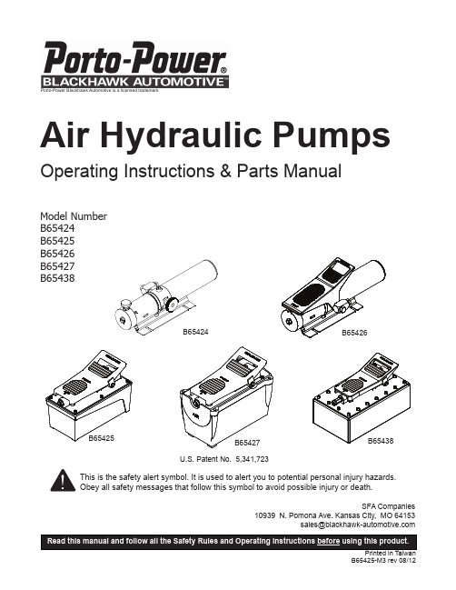
Porto-Power Blackhawk Automotive is a licensed trademarkOperating Instructions & Parts ManualModel Number B65424SFA Companies10939 N. Pomona Ave. Kansas City, MO 64153******************************This is the safety alert symbol. It is used to alert you to potential personal injury hazards.Obey all safety messages that follow this symbol to avoid possible injury or death.Air Hydraulic PumpsPRODUCT DESCRIPTIONPorto-Power Blackhawk Air Hydraulic Pumps are engineered to meet factory standard for performance and safety. Its unique hydraulic circuit allows quick displacement of hydraulic fluid under no load conditions and easy pumping in loaded conditions. These air actuated pumps supply compressed hydraulic fluid to compatible applications i.e. rams, presses, spreaders, compactors and crimping machines, anywhere that 10,000 PSI of fluid pressure is needed. Special skill, knowledge and training may be required for a specific task and the product may not be suitable for all the jobs described above. Unsuitable applications would include applications that call for a device to move, level or support persons, animals, hazardous materials, mobile homes/ dwellings in general, mirrors and/or plate glass, and/or to connect/secure hatches, components, etc. between bulkheads. The user must ultimately make the decision regarding suitability of the product for any given task and assume the responsibility of safety for himself or herself and others in the work area.WARNING: To reduce the risk of personal injury property damage, ensure that the rated working pressure of each pressurized attachment be equal to or greater than the rated working pressure developed by the hydraulic pump.Always check connections before using.Use only those adapters and attachments provided and approved by the manufacturer.SAFETY and GENERAL INFORMATIONSave these instructions. For your safety, read and understand the information contained within. The owner and operator shall have an understanding of this product and safe operating procedures before attempting to use this product. Instructions and Safety information shall be conveyed in the operators native language before use of this product is authorized. Make certain that the operator thoroughly understands the inherent dangers associated with the use and misuse of the product. If any doubt exists as to the safe and proper use of this product as outlined in this factory authorized manual, remove from service.Inspect before each use. Do not use if broken, bent, cracked or otherwise damaged parts are noted. If any component of this product has been or suspected to have been subjected to a shock load (a load dropped suddenly, unexpectedly upon it), discontinue use until checked out by an Porto-Power Blackhawk Automotive authorized service center. Owners and operators of this equipment shall be aware that the use and subsequent repair of this equipment may require special training and knowledge. It is recommended that an annual inspection be done by qualified personnel and that any missing or damaged parts, decals, warning/safety labels or signs be replaced with factory authorized replacement parts only. Any component of this Porto-Power Kit that appears to be damaged in any way, is worn or operates abnormally shall be removed from service immediately until such time as it can be repaired/replaced. Labels and Operator's Manuals are availableReservoir CapSPECIFICATIONSModel Number Usable OilCapacity(in3)RatedPressure(psi)Output Flow Rate(in3/min)Input AirPressure(psi)Output PortThread(Oil)Input PortThreads(Air)No Load LoadB6542436.610,000619110 - 1753/8” -18NPTF1/4” - 18NPTB65426B6542591.56611 B654271226512 B65438231.96512BEFORE USE AND SET UP1. Familiarize yourself with the specifications and illustrations in this owners manual. Know your pump, its limitations and how it operates before attempting to use. Refer to specification chart on page 3 for details of oil port thread size, usable oil capacity, and more.2. For model B65425, B65427 & B65438: Replace shipping plug (red color) with air vent plug (black color) before use.3. Air Connection: Remove plastic cap, connect suitable air supply to air input port. Air input port is designed to fit the popular 1/4" NPT air nipple (not included). Ensure that your air source can dedicate 7.8CFM @ 110~175 PSI to each pump operated.4. Hydraulic Connection: Clean all areas around the oil port of pump and ram. Inspect all threads and fitting for signs of wear or damage and replace as needed. Clean all hose ends, couplers and union ends. Remove the manifold plug, then connect oil output port to suitable fittings and application/ram.IMPORTANT : Always secure threaded port connections with high grade, non-hardening pipe thread sealant. Teflon tape can be used if only one layer of tape is used and it is applied carefully, two threads back, to prevent the tape from being introduced into hydraulic system, which could cause jamming of precision-fit parts.To reduce the risk of personal injury and/or property damage, Hydraulic connections must be securely fastened before building pressure in the system. Release all system pressure before loosening any hydraulic connection in the system.Always monitor pressure, load or position using suitable equipment. Pressure may be monitored by means of an optional manifold and gauge. Load may be monitored by means of a load cell and digital indicator. Correct application position can only be determined by the operator of the equipment.For Model B65424: (Hand Button Pump)1. To extend the cylinder:a. Close release valve by turning it clockwise firmly.b. Depress the hand button on top of the air input port until desired pressure, load or position is reached.2. To hold the cylinder in position, simply release the hand button to deactivate the pump.3. To retract cylinder, open release valve by turning it counter-clockwise slowly.For Models B65425, B65426, B65427 & B65438:1. To extend the ram, depress on the foot pedal marked "Pump " (horizontal portion) until desired pressure, load or position is reached.2. To hold the ram in position, release the foot pedal to deactivate the pump.3. To retract the ram, depress the release valve by stepping on the foot pedal marked "Release " (raised, stirrup shaped portion).Note: Never operate a pump which is disconnected from application. If operate in this condition, the hose and connections will become pressurized. This increases burst hazard. Damage may occur to pump and its components.MAINTENANCEImportant: Use only good quality hydraulic fluid. Never use brake fluid, transmission fluid, turbine oil, motor oil, alcohol, glycerin etc. Use of other than good quality hydraulic oil will void warranty and damage the pump, hose, and application. We recommend Hein-Werner HW93291 or equivalent.1. Inspect hoses and connections daily. Replace damaged components immediately.2. Tighten connections as e non-hardening pipe thread compound when servicing connections.Adding Hydraulic Fluid1. Depressurize and disconnect hydraulic hose from application/ ram.a. For Model B65424 & B65426:With pump in its vertical position, remove the reservoir cap located on the reservoir.b. For Model B65425, B65427 & B65438:With pump in its upright, horizontal position, remove the air vent plug located on the top plate of the reservoir.2. Use a small funnel to fill the oil to within 3/4" (19mm) of the opening.3. Wipe up any spilled fluid and reinstall the air vent plug/reservoir cap.Changing Hydraulic Fluid1. For best results, change fluid once a year or every 300 hours of use.2. Repeat #2 above, then pour used fluid into a sealable container.3. Dispose of fluid in accordance with local regulations.4. Fill with a good quality hydraulic fluid as recommended above. Reinstall air vent plug/ reservoir cap.LubricationWhen pump is operated on daily basis, the manufacturer recommends installing an inline oiler and air dryer. Use SAE grade oil (5W to 30W).TROUBLESHOOTING GUIDEThe following information is intended as an aid in determining if problem exists. Pump should be repaired only by authorized Porto-Power Service Center. For repair service, contact service center in your area.SymptomPossible CausesCorrective ActionApplication does not extend, move or respond to pressurized fluid• Overload condition • Loose couplers • Faulty couplers • Pump malfunction • Inadequate air supply• Remedy overload condition • Tighten couplers • Replace couplers• Contact service center• Ensure air source can dedicate 7.8 CFM @ 110~175 PSI Application responds topressurized fluid, but system does not maintain pressure • Overload condition• Pump or valve malfunction • Application/connection leaking• Remedy overload condition • Contact service center• Replace application/connection Application responds slower than normal • Loose connection or coupler • Restricted hydraulic line or fitting• Application/connection leaking • Tighten connection or coupler • Clean and replace if damaged • Replace application/connectionApplication does not return fluid to pump (i.e. ram will not retract)• Malfunctioning coupler, damaged application • Secure load by other means . Depressurize pump and hose,remove coupler and/or application, then renew or replace Application does not fully extend (ram or spreader)• Reservoir overfilled• Fluid level in pump is low• Secure load by other means . Depressurize pump and hose, remove application, then drain fluid to proper level• Secure load by other means . Depressurize pump and hose, remove application, then fill fluid to proper levelPoor performance • Fluid level in pump is low• Ensure proper fluid levelStorage1. When not in use, depressurize and disconnect hydraulic pump from application.2. Wipe clean, thoroughly and store in clean, dry environment. Avoid temperature extremes.3. For transportation or long storage, replace the air vent plug with shipping plug (for model B65425, B65427& B65438).REPLACEMENT PARTS(refer to page 6 thru 15)Not all components of the pump are replacement items, but are illustrated as a convenient reference of location and position in the assembly sequence. When ordering parts, give Model number, serial number and description below. Call or write for current pricing: SFA Companies 10939 N. Pomona Ave. Kansas City, MO 64153, U.S.A.Tel:(816)891-6390Fax:(816)891-6599E-Mail:******************************Replacement Parts Illustration for Model B65424Replacement Parts List for Model B65424Item Part#Description Qty 1A18-6-5011-101Reservoir cover1 2*O-ring1 3A18-6-5012-204Cover1 4A18-6-5003-102Cylinder1 5649-1-0050-055Screw5 6A18-6-5008-203Cover adapter1 7*Reservoir1 8A18-6-5004-205Steel bar1 9*Bundle1 10644-1-0060-301Screw1 11H28-6-1302-105Release turntable1 12601-4-0030-040Spring pin1 13A16-6-5007-106Release valve1 14A16-6-5008-108Release valve seat1 15*O-ring1 16*Back-up ring1 17*O-ring1 18601-7-0008-009Steel ball2 19522-8-0113-107Filter1 20512-2-0063-104Compression spring1 21601-7-0012-000Steel ball1 22552-2-0080-106Bevel compression spring1 23*Special Washer1 24A16-6-5006-104Screw1 25A17-6-1216-102Needle valve1 26512-2-0067-010Compression spring1 27A17-5-1603-300Adjust screw1 28*Special Washer2 29414-6-1215-509Screw1 30D05-6-1001-106Nut1 31A18-6-5001-209Oil outlet valve seat1 32A18-6-5002-201Adapter1 33*Back-up ring3 34*O-ring3 35667-5-0180-009C-clip1Item Part#Description Qty 36A16-6-5009-908Base1 37A17-6-1002-103Muffler1 38666-5-0250-108C-clip1 39A18-6-5009-104Plank1 40A18-6-5028-108Bundle1 41A18-6-5014-107Cylinder loop1 42A59-6-1013-105Pump1 43*U-cup1 44*Back-up ring1 45A27-6-2023-205Bush1 46A18-6-5024-100Pump cover1 47512-2-0410-017Compression spring1 48A18-3-5026-106Piston assy.1 49A17-4-2100-500Air piston assy.1 50A18-5-5016-105Cylinder1 51*Washer4 52A18-6-5030-105Screw bushing2 53649-1-0050-046Screw2 54*Washer1 55A16-6-5003-108Cylinder cover1 56A17-6-1105-103Plastic cover1 57A16-6-5005-102Washer1 58552-2-0108-010Bevel compression spring1 59*Washer1 60A16-6-5001-104Air entrance valve1 61*O-ring1 62*O-ring1 63A16-6-5002-106Air entrance valve seat1 64A16-6-5004-100Button1 65644-1-0060-05311Screw1 (*)A16-3-9900-100Seal kit-(*) indicated items included in, and available only as part of Seal KitReplacement Parts Illustration for Model B65425Replacement Parts List for Model B65425(*) indicated items included in, and available only as part of Repair kitItem Part#Description Qty 1A57-6-2001-108Foot pedal 12*E-clip23A57-6-2003-102Foot pedal axle 14D05-6-1001-106Manifold plug 15A57-6-3007-105Noise suppressor 16666-5-0160-107C-clip 17*Back-up ring 28*O-ring 29A57-6-4002-201Oil outlet valve 110512-2-0043-108Compression spring 111601-7-0009-001Steel ball 112511-7-0410-102O-ring 113649-1-0050-055Allen Screw 614*Copper washer 615A57-6-1603-202Reservoir top plate 116644-1-0060-053Screw 117503-9-0050-106Steel ball seat 118601-7-0006-005Steel ball 119*Special washer 220A59-6-1017-102High pressure valve 121A17-6-1216-102Valve stem122512-2-0067-010Compression spring 123A17-5-1603-300Pressure adjust nut 124601-7-0008-009Steel ball 125A59-6-1015-108Oil entrance valve 126520-8-0134-101Filter 127*Gasket 128A57-6-1601-107Reservoir 129649-1-0060-122Allen Screw 430A57-6-1002-105Motor cover 131A17-6-2105-108Gasket 232A17-4-2100-500Air piston assy.133A57-6-1003-107Cylinder 134A57-3-1011-108Piston assy.135512-2-0410-017Compression spring 136A57-6-1014-102Piston cover 137A57-6-2023-108Bushing 138573-7-0120-105Back-up ring 139*U-cup 140A59-6-1013-105Pump piston1Item Part#Description Qty 41A57-6-1016-106Washer 142H18-6-8103-104Special washer 143A57-6-1001-204Base 144A57-6-1605-105Gasket 145511-7-0140-200O-ring246512-2-0092-101Compression spring 147649-1-0040-007Allen Screw 148A57-6-5004-109Air entrance cap 149511-7-0053-104O-ring150A57-6-5001-103Air entrance base 151A17-6-1105-103Plastic cap (air)152A57-6-5003-107Air entrance valve 153511-7-0080-309O-ring 154649-1-0050-046Allen Screw 655a A57-3-5007-107Shipping plug (red)155b A57-3-1900-109Air vent plug (black)156512-2-0061-100Compression spring 157644-1-0040-204Screw158*Compression spring 159503-9-0035-100Steel ball block 160601-7-0003-009Steel ball 161A57-6-3003-305Release valve 162A57-6-3004-307Release valve seat 163*O-ring 164*Back-up ring 165552-2-0010-105Compression spring 166*Release valve pin 167A57-6-3001-112Release valve guide 168*O-ring 169*Gasket170A17-6-1002-103Noise suppressor 171 6 66-5-0250-108C-clip 172A57-6-4001-209Oil manifold 1(*)A57-3-9901-101Repair kit1Replacement Parts Illustration for Model B65426Replacement Parts List for Model B65426Item Part#Description Qty 1A18-6-5011-101Reservoir cap1-2* O-ring1 3A18-6-5012-204Cover1 4A18-6-5003-102 Cylinder15649-1-0050-055 Screw M5x0.8x16L56A18-6-5008-203 Cover adapter1 7*Reservoir1 8A18-6-5004-205Steel rod1 9*Hose clamp1 10522-8-0113-107Filter1 11512-2-0060-034Compression spring1 12503-9-0075-102 Steel ball block1 13601-7-0007-007Steel ball1 14*Copper washer115A18-6-5006-209Release valve116*O-ring2 17A18-6-5005-106Release bar1 18*511-7-0050-300 O-ring2 19A18-6-5007-100Release valve seat1 20511-2-0181-103Compression spring1 21A18-6-5023-108Spring cover122677-5-0050-105 E-clip1 23A18-6-5021-104 Foot pedal124A17-6-2601-100Screw D10.8x14.5L225*O-ring 226A17-5-1603-300Adjust screw1 27512-2-0067-010 Compression spring1 28A17-6-1216-102 Valve stem1 29A18-6-5018-105High press. valve seat1 30*O-ring5 31A18-6-5010-200Base1 32601-7-0005-009 Steel ball D1/4” 2 33512-2-0063-104 Compression spring1 34A17-6-1002-103 Noise suppressor1 35666-5-0250-108C-clip1 36*Back-up ring3 37667-5-0180-009 C-clip1 38A18-6-5002-100 Adapter 1 39D05-6-1001-106Manifold plug1 40A18-6-5001-209Oil outlet valve seat1Item Part#Description Qty 41A18-6-5009-104Base plate1 42552-2-0008-108 Compression spring1 43A18-6-5028-108Hose clamp1 44A18-6-5014-107Gasket1 45*Special washer1 46A18-6-5013-105Pump piston1 47*U-cup1 48*Back-up ring1 49A27-6-2023-205Bushing1 50A18-6-5024-100A18-6-5024-100151512-2-0410-017Compression spring152A18-3-5026-106Piston assy.1 53A17-4-2100-500Air piston assy. 1 54A18-5-5016-105Cylinder1 55*Washer 4 56A18-6-5030-105Screw bushing2 57649-1-0050-046Screw258Washer 159A18-5-5017-107Motor cover1 60A17-6-1105-103Plastic cap161601-4-0030-059 Spring pin262A18-6-5019-107Air entrance valve1 63*O-ring 1 64*O-ring 1 65A18-6-5020-102Air entrance valve seat1 (*)A18-3-9900-104Repair kit-(*) indicated items included in, and available only as part of Repair kitReplacement Parts Illustration for Model B65427Replacement Parts List for Model B65427 Item Part#Description Qty1a N/A Foot pedal11b N/A Steel bar12A57-4-6003-100Foot pedal w/ steel bar-3*Pedal axle e-clip24A57-6-2003-102Pedal axle15D05-6-1001-106Manifold plug (oil output port)16A58-6-6008-109Output coupler1 7A57-6-3007-105Noise suppresor1 8666-5-0160-107C-clip 1 9*O-ring2 10*Back-up ring2 11A57-6-4002-201Oil discharge valve1 12512-2-0043-108Compression spring1 13601-7-0009-001Steel ball1 14511-7-0410-102O-ring115649-1-0050-055Allen screw(M5x0.8x15L)1216*Copper washer 10 17A58-5-1603-102Top reservoir plate1 18644-1-0060-053Set screw1 19503-9-0050-106Steel ball seat1 20601-7-0006-005Steel ball1 21*Crush washer222A58-6-1017-105Pressure relief valve cylinder123A17-6-1216-102Pressure relief valve stem124512-2-0067-010Compression spring 125A17-5-1603-300Pressure relief valve screw126A58-6-2201-103Reservoir spacer1 27649-1-0040-108Allen screw4 28601-7-0008-009Steel ball1 29A58-6-1015-101Oil intake valve1 30520-8-0134-101Filter1 31*Gasket1 32A58-5-1602-100Reservoir 1 33649-1-0060-122Allen Screw4 34A57-6-1002-105Motor cover1 35A17-6-2105-108Gasket2 36A17-4-2100-500Air motor piston assy. 137A57-6-1003-107Cylinder, air motorpiston138A27-3-2200-102Pump piston1 39512-2-0410-017Compression spring 1 40A57-6-1014-102Pump piston guide1Item Part#Description Qty 41A27-6-2023-205Bushing1 42573-7-0120-105Back-up ring1 43*U-cup1 44A58-6-1013-107Pump piston cylinder1 45A57-6-1016-106Spacer1 46H18-6-8103-104Crush washer1 47A57-6-1001-204Base1 48A57-6-1605-105Gasket1 49511-7-0140-200O-ring2 50512-2-0092-101Compression spring1 51649-1-0040-007Allen screw (M4 x 0.7x 6L)1 52A57-6-5004-109Air intake cap1 53511-7-0053-104O-ring1 54A57-6-5001-103Air manifold1 55A17-6-1105-103Plastic cap (air)1 56A57-6-5003-107Air intake valve1 57511-7-0080-309O-ring1 58649-1-0050-046Allen screw(M5x0.8x30L)6 59a A57-3-5007-107Shipping plug (red)1 59b A57-3-1900-109Air vent plug (black)1 60512-2-0061-100Compression spring1 61644-1-0040-204Lower assy. bolt, releasevalve1 62*Compression spring1 63503-9-0035-100Steel ball seat1 64601-7-0003-009Steel ball1 65A57-6-3003-305Release valve1 66A57-6-3004-307Release valve seat1 67*O-ring1 68*Back-up ring1 69552-2-0010-105Compression spring 1 70*Release valve pin1 71A57-6-3001-112Release valve cap1 72*O-ring1 73*Gasket 1 74666-5-0250-108C-clip1 75A17-6-1002-103Noise suppresor1 76A57-6-6004-104Oil manifold 1 77A57-6-5101-107Detent spring1 78A57-6-6005-106Dust boot1 (*)A58-3-9903-102Repair kit-(*) indicated items included in, and available only as part of Repair kitReplacement Parts Illustration for Model B65438Replacement Parts List for Model B65438(*) indicated items included in, and available only as part of Seal KitItem PA3801 Part#Description Qty 1a N/A Foot pedal 11b N/ASteel bar12A57-4-6003-100Foot pedal w/ steel bar -3*Pedal axle e-clip 24A57-6-2003-102Pedal axle15D05-6-1001-106Manifold plug (oil output port)16A57-6-3007-105Noise suppresor 17666-5-0160-107C-clip 18*O-ring29*Back-up ring210A57-6-4002-201Oil discharge valve 111512-2-0043-108Compression spring 112601-7-0009-001Steel ball 113511-7-0410-102O-ring114649-1-0060-040Allen screw (M6 x 1 x 15L)1815*Washer1816A57-6-6008-102Reservoir top plate 117644-1-0060-05311Set screw 118503-9-0050-106Steel ball seat 119601-7-0006-005Steel ball120*Crush washer221A59-6-1017-102Pressure relief valve cylinder 122A17-6-1216-102Pressure relief valve stem 123512-2-0067-010Compression spring124A17-5-1603-300Pressure relief valve screw 125601-7-0008-009Steel ball126A57-6-6006-108Oil intake valve 127520-8-0134-101Filter128A57-6-6009-104Reservoir gasket 129A57-6-6007-201Reservoir130649-1-0060-122Thru bolt, air motor 431A57-6-1002-105End plate, air motor 132A17-6-2105-108Gasket233A17-4-2100-500Air motor piston134A57-6-1003-107Cylinder, air motor piston 135A27-3-2200-102Pump piston136512-2-0410-017Compression spring 137A57-6-1014-102Pump piston guide 138A27-6-2023-205Bushing139573-7-0120-105Back-up ring 140*U-cup1Item PA3801 Part#DescriptionQty 41A58-6-1013-107Pump piston cylinder 142A57-6-1016-106Spacer143H18-6-8103-104Crush washer144A57-6-1001-204Base, hydraulic unit 145A57-6-1605-105Gasket 146511-7-0140-200O-ring247512-2-0092-101Compression spring 148649-1-0040-007Allen screw 149A57-6-5004-109Air intake cap 150511-7-0053-104O-ring151A57-6-5001-103Air manifold 152A57-6-2062-108Intake coupler 153A17-6-1105-103Plastic cap (air)154A57-6-5003-107Air intake valve 155511-7-0080-309O-ring156649-1-0050-046Allen screw657a A57-3-5007-107Shipping plug (red)157b A57-3-1900-109Air vent plug (black)158512-2-0061-100Compression spring 159644-1-0040-204Allen screw160*Compression spring 161503-9-0035-100Steel ball seat 162601-7-0003-009Steel ball163A57-6-3003-305Release valve164A57-6-3004-307Release valve guide 165*O-ring166*Back-up ring167552-2-0010-105Compression spring 168*Release valve pin 169A57-6-3001-112Release valve guide 170*O-ring 171*Gasket172A17-6-1002-103Noise suppresor 173666-5-0250-108C-clip174A57-6-6004-104Oil manifold 175A57-6-6005-106Dust boot 176A57-6-5101-107Detent spring 177649-1-0050-055Allen screw 2(*)A57-3-9911-104Seal kit-ONE YEAR LIMITED WARRANTYFor a period of one (1) year from date of purchase, SFA Companies will repair or replace, at its option, without charge, any of its products which fails due to a defect in material or workmanship under normal usage. This limited warranty is a consumer's exclusive remedy.Performance of any obligation under this warranty may be obtained by returning the warranted product, freight prepaid, to SFA Companies Warranty Service Department, 10939 N. Pomona Ave., Kansas City, MO 64153.Except where such limitations and exclusions are specifically prohibited by applicable law.(1) THE CONSUMER'S SOLE AND EXCLUSIVE REMEDY SHALL BE THE REPAIR OR REPLACEMENT OFDEFECTIVE PRODUCTS AS DESCRIBED ABOVE.(2)SFA COMPANIES SHALL NOT BE LIABLE FOR ANY CONSEQUENTIAL OR INCIDENTAL DAMAGE OR LOSSWHATSOEVER.(3) ANY IMPLIED WARRANTIES, INCLUDING WITHOUT LIMITATION THE IMPLIED WARRANTIES OFMERCHANTABILITY AND FITNESS FOR A PARTICULAR PURPOSE, SHALL BE LIMITED TO ONE YEAR, OTHERWISE THE REPAIR, REPLACEMENT OR REFUND AS PROVIDED UNDER THIS EXPRESS LIMITED WARRANTY IS THE EXCLUSIVE REMEDY OF THE CONSUMER, AND IS PROVIDED IN LIEU OF ALL OTHER WARRANTIES, EXPRESS OR IMPLIED.(4) ANY MODIFICATION, ALTERATION, ABUSE, UNAUTHORIZED SERVICE OR ORNAMENTAL DESIGN VOIDSTHIS WARRANTY AND IS NOT COVERED BY THIS WARRANTY.Some states do not allow limitations on how long an implied warranty lasts, so the above limitation may not apply to you. Some states do not allow the exclusion or limitation of incidental or consequential damages, so the above limitation or exclusion may not apply to you. This warranty gives you specific legal rights, and you may also have other rights which vary from state to state.SFA Companies10939 N. Pomona Ave. Kansas City, MO 64153Tel: 888-332-6419E-mail:******************************。
- 1、下载文档前请自行甄别文档内容的完整性,平台不提供额外的编辑、内容补充、找答案等附加服务。
- 2、"仅部分预览"的文档,不可在线预览部分如存在完整性等问题,可反馈申请退款(可完整预览的文档不适用该条件!)。
- 3、如文档侵犯您的权益,请联系客服反馈,我们会尽快为您处理(人工客服工作时间:9:00-18:30)。
ga 10b空气泵说明书
一.正确的充气过程:
1.确保所充气瓶的检验日期在规定的检验日期内,检查气瓶的外
观情况,无任何的损伤现象。
检查气瓶阀,压力表。
无任何的
损伤迹象。
2.检查空气压缩机的操作维护记录,确保压缩机得滤芯,润滑油
在允许的使用时间内,确保压缩机五任何故障,按制造商提供
的使用说明书正确使用压缩机。
3.气瓶第一次充气时,气瓶内无压力,不要一次充气到最高压力,
一般先充气致15Ma~17Ma,取下冷却10~15分钟后再充。
这
点对于国内制造的空气压缩机尤其重要。
4.如使用防爆充气柜且充气柜带水槽的话,请尽量使用这种设备
且带冷却水,这种充气设备冷却效果最好,如使用此设备,充
气过程可一次完成。
5.充气过程中操作人员不得离开操作现场,要时常注意充气压
力,压力表和瓶阀的温度,特别是要注意不得“过压”充气。
6.如果使用的是国产的充气泵,要特别注意充气温度。
充气温度
直接会影响到压力表,瓶阀。
7.严格按制造商的使用说明操作压缩机:对于每分钟100升的小
型压缩机,每隔15分钟一定要放水、排污一次,每充5瓶后
一定要让压缩机“休息”10分钟,以确保压缩机处于最佳的工
作状态并延长压缩机的使用寿命。
按使用说明书的规定更换滤芯和润滑油。
8.气瓶和压缩机的连接只能用手工完成,不得使用工具强行操
作。
9.气瓶的打开和关闭不得使用太大的力矩,尤其要克服这样的心
理:好象气瓶里面的30Ma的压力,非得要用很大的力矩关瓶,关闭瓶阀时不需使用大力矩,只要将气瓶关紧即可。
10.在有良好通风的环境中使用压缩机,使用时避免汽车尾气,不
得在操作现场抽烟。
11.充气及使用压缩机要经过培训合格后的人才能进行此项工作。