ZGO正港手表504说明书
Omega 产品用户指南说明书

e-mail:**************User’s GuideTQ504Torque TransducerShop online atINDEX1.Applications and typical attributes ...............................................Page 12.Description of the measurement system ......................................Page 12.1Mechanical design .................................................................Page 12.2Electrical design .....................................................................Page 22.3Angle-of-rotation transducer ...............................................Page 33.Electrical connection of the torque transducer ............................Page 43.1Connector pin assignments ..................................................Page 53.1.1Signals, angle outputs ...........................................................Page 63.2Laying of the output signal cables ......................................Page 63.3Placement of conductors in cable ........................................Page 64.Mechanical installation of the torque transducer........................Page 84.1Suggestions for installation ..................................................Page 85.Mechanical calibration .....................................................................Page 95.1Assembly of a simple calibrating setup............................Page 105.2Sample calculation of lever arm length.............................Page 105.3Electrical calibration.............................................................Page 116.Maintenance......................................................................................Page 117.Troubleshooting guide for transducer shaft...............................Page 12See Data Sheet for technical specificationsi1.Applications and typical attributes• Torque transducer with inductive angular position measurement system.• Measurement of constant and variable torques.• Torque measurement on a rotating shaft.• For laboratory, production and quality assurance applications.• Built- in instrument amplifier.• Built- in angle-of-rotation transducer.2.Description of the measurement system2.1Mechanical design• The transducer consists of a stator through which a bearing-mounted shaft passes.• A certain length of the shaft is utilized to convert the torque into a proportional torsional angle.• This torsional angle or angle of twist is measured between the two ends of this shaft length by an inductive (wave-form) angular position measurement system.• The inductive angular position measurement system converts the angle of twist into a proportional electrical signal.1• The electrical power for operation of the inductive angular positionmeasurement system, which rotates along with the shaft, is provided by meansof a rotary transformer.• The electrical output signal, which is proportional to the torque, is transferredto the stator by a second rotary transformer.• The connection box on the stator contains the electronics, the power supplyunit, and the instrument amplifier.2.2Electrical designThe built-in electronics comprise the following functional groups:• Oscillator for generation of the AC input voltage• Preamplifier for the output signal• Phase-sensitive rectifier for conversion of the AC output signal into a DCvoltage• Output amplifier22.3Angle-of-rotation transducer1.Rotating shaft2.Encoder disk3.Double-arm photoelectric barrier4.Open-collector output (external pull-up resistor required)*Features:• 360 slots in the encoder disk• Two double-arm photoelectric barriers 90°apart.• Number of pulses generated proportional to angle of rotation.* The ohmic value of the resistor depends on the maximum speed of rotation andthe cable length (e.g. 1500 rpm and a 4 m cable, R=3.3kΩ).33. Electrical connection of the torque transducer• Cable type: at least 12 conductors, e.g. LIYCY12 x 0.14• Max. cable length: 15 m43.1 Connector pin assignmentsDescription of interface for Type, art.-no.: 7203Angle outputs: open collector outputs with internal 10k Ωpull-up to +Vop Built in connector: Binder Series 680, type 09-0331-80-12 or equivalent Cable diagram with plugs on both sides5Top view of connector on transducer3.1.1Signals, angle outputs3.2Laying of the output signal cables-Note on safety-• Do not lay together with control lines or lines carrying a high current.• Do not lay close to strong electromagnetic fields, e.g. those of transformers,welding equipment, contactors, motors, etc.• If the above is unavoidable, the cables must be laid in grounded heavygage steel conduit.• At the transducer, lay the cables in a sling in order to prevent vibration-induced damage to them.3.3Placement of conducters in cableIn order to prevent the measurement signal being distorted by the angle pulses,the corresponding conductors should be separated within the cable.6The cable length has virtually no influence on the measurement signal, but in the case of the angle outputs the external pull-up resistances must be properly adjusted.74.Mechanical installation of the torque transducerTransducer with fixed stator:2 holes are provided in the transducer housing for this purpose.• Use displaceable couplings as both shaft ends that are capable of accommodating angular, radial and axial misalignment.• Good results have been obtained with miniature couplings stiff against torsion such as those described in data sheet 8303.At torques of 50 Nm or greater, it is also possible to install the transducer without fixed stator:• In this case, use flexible couplings at both ends.Caution:during installation no impermissibly high torques may beallowed to arise between the two ends of the torque transducer shaft.4.1Suggestions for installationTransducer with fixed stator and couplings able to accommodate angular, radial and axial misalignment at both ends.8This type of installation is possible at torques of 50 Nm and greater.5.Mechanical calibrationTo perform this, a calibration setup with lever arm and weights is needed tocreate a torque.Steps for calibration:a)Apply the rated torque to the transducer, then remove the load again.b)Precisely adjust the transducer to the zero point.c) Apply a known torque to the transducer.d) Set the indicator to the proper value.Recording of a calibration curve:a) Calibrate the transducer as described above.b) Progressively apply greater torques to the transducer in steps of 1/10 up tothe full rated torque. Then gradually remove the torque in the same way. Ateach step, wait at least 30 seconds for the torque reading to stabilize, and thenrecord.95.1A simple calibrating setup5.2Sample calculation of lever arm length10eg. m = 1 kg. Mt = 10 NmL =10Nm sec 21 kg _ 9.80665= 1,0197 m5.3Electrical calibrationA calibration control facility is integrated in the transducer to permit electrical calibration.Procedure for electrical calibration:• Remove all mechanical loads from the transducer (no torque).• Apply the calibration voltage Vc to pin K referenced to pin E.• An output signal corresponding to the rated torque will be emitted.6.Maintenance• Type IE transducers require virtually no maintenance.• The service life expectancy of the bearings within the rated temperature range is approx. 20,000 hours.• The service life expectancy of the bearing within the operating temperature range is approx. 10,000 hours.• The bearings can only be replaced in the factory.• For high-precision applications: recalibrate the transducer once annually (calibration at the factory or using an appropriate calibration setup).• Once a month, check the cable connectors to make sure that they are securely seated.• Check the cables for damage once a month.117.Troubleshooting guide for transducer shaft12ProblemProbable causesRemedial actionShaft does not rotate Bearings are defective due to:freelya) Torsional or flexional vibrations b) Excessive axial or radial loads Return to factoryc) Old or soiled bearings d) Bent shaft Zero point displacement Rotational vibration Readjust zero point on ≤2 %Shock forcesinstrument amplifier Zero offset between 2%Transducer has been overloaded The zero point can be and 5% of range Shock forcesrecalibrated once at Rotational vibrationthe instrument amplifier Transducer has Transducer has been overloaded hysteresis between by changing loads or rotational Return to factoryclockwise and counter-Rotation vibrationclockwise torqueNOTES: 13WARRANTY/DISCLAIMEROMEGA ENGINEERING, INC. warrants this unit to be free of defects in materials and workmanship for a period of 13 months from date of purchase. OMEGA’s WARRANTY adds an additional one (1) month grace period to the normal one (1) year product warranty to cover handling and shipping time. This ensures that OMEGA’s customers receive maximum coverage on each product.If the unit malfunctions, it must be returned to the factory for evaluation. OMEGA’s Customer Service Department will issue an Authorized Return (AR) number immediately upon phone or written request. Upon examination by OMEGA, if the unit is found to be defective, it will be repaired or replaced at no charge. OMEGA’s WARRANTY does not apply to defects resulting from any action of the purchaser, including but not limited to mishandling, improper interfacing, operation outside of design limits, improper repair, or unauthorized modification. This WARRANTY is VOID if the unit shows evidence of having been tampered with or shows evidence of having been damaged as a result of excessive corrosion; or current, heat, moisture or vibration; improper specification; misapplication; misuse or other operating conditions outside of OMEGA’s control. Components which wear are not warranted, including but not limited to contact points, fuses, and triacs.OMEGA is pleased to offer suggestions on the use of its various products. However, OMEGA neither assumes responsibility for any omissions or errors nor assumes liability for any damages that result from the use of its products in accordance with information provided by OMEGA, either verbal or written. OMEGA warrants only that the parts manufactured by it will be as specified and free of defects. OMEGA MAKES NO OTHER W ARRANTIES OR REPRESENTATIONS OF ANY KIND WHATSOEVER, EXPRESS OR IMPLIED, EXCEPT THAT OF TITLE, AND ALL IMPLIED WARRANTIES INCLUDING ANY WARRANTY OF MERCHANTABILITY AND FITNESS FOR A PARTICULAR PURPOSE ARE HEREBY DISCLAIMED. LIMITATION OF LIABILITY: The remedies of purchaser set forth herein are exclusive, and the total liability of OMEGA with respect to this order, whether based on contract, warranty, negligence, indemnification, strict liability or otherwise, shall not exceed the purchase price of the component upon which liability is based. In no event shall OMEGA be liable for consequential, incidental or special damages.CONDITIONS: Equipment sold by OMEGA is not intended to be used, nor shall it be used: (1) as a “Basic Component” under 10 CFR 21 (NRC), used in or with any nuclear installation or activity; or (2) in medical applications or used on humans. Should any Product(s) be used in or with any nuclear installation or activity, medical application, used on humans, or misused in any way, OMEGA assumes no responsibility as set forth in our basic WARRANTY/DISCLAIMER language, and, additionally, purchaser will indemnify OMEGA and hold OMEGA harmless from any liability or damage whatsoever arising out of the use of the Product(s) in such a manner.RETURN REQUESTS/INQUIRIESDirect all warranty and repair requests/inquiries to the OMEGA Customer Service Department. BEFORE RETU RNING ANY PRODU CT(S) TO OMEGA, PU RCHASER MU ST OBTAIN AN AU THORIZED RETU RN (AR) NU MBER FROM OMEGA’S CU STOMER SERVICE DEPARTMENT (IN ORDER TO AVOID PROCESSING DELAYS). The assigned AR number should then be marked on the outside of the return package and on any correspondence.The purchaser is responsible for shipping charges, freight, insurance and proper packaging to prevent breakage in transit.FOR WARRANTY RETURNS, please have the following information available BEFORE contacting OMEGA:1.Purchase Order number under which the productwas PURCHASED,2.Model and serial number of the product underwarranty, and3.Repair instructions and/or specific problemsrelative to the product.FOR NON-WARRANTY REPAIRS,consult OMEGA for current repair charges. Have the following information available BEFORE contacting OMEGA: 1. Purchase Order number to cover the COSTof the repair,2.Model and serial number of the product, and3.Repair instructions and/or specific problemsrelative to the product.OMEGA’s policy is to make running changes, not model changes, whenever an improvement is possible. This affords our customers the latest in technology and engineering.OMEGA is a registered trademark of OMEGA ENGINEERING, INC.© Copyright 2002 OMEGA ENGINEERING, INC. All rights reserved. This document may not be copied, photocopied, reproduced, translated, or reduced to any electronic medium or machine-readable form, in whole or in part, without the prior written consent of OMEGA ENGINEERING, INC.Where Do I Find Everything I Need for Process Measurement and Control?OMEGA…Of Course!Shop online at TEMPERATUREⅪߜThermocouple, RTD & Thermistor Probes, Connectors, Panels & AssembliesⅪߜWire: Thermocouple, RTD & ThermistorⅪߜCalibrators & Ice Point ReferencesⅪߜRecorders, Controllers & Process MonitorsⅪߜInfrared PyrometersPRESSURE, STRAIN AND FORCEⅪߜTransducers & Strain GagesⅪߜLoad Cells & Pressure GagesⅪߜDisplacement TransducersⅪߜInstrumentation & AccessoriesFLOW/LEVELⅪߜRotameters, Gas Mass Flowmeters & Flow ComputersⅪߜAir Velocity IndicatorsⅪߜTurbine/Paddlewheel SystemsⅪߜTotalizers & Batch ControllerspH/CONDUCTIVITYⅪߜpH Electrodes, Testers & AccessoriesⅪߜBenchtop/Laboratory MetersⅪߜControllers, Calibrators, Simulators & PumpsⅪߜIndustrial pH & Conductivity EquipmentDATA ACQUISITIONⅪߜData Acquisition & Engineering SoftwareⅪߜCommunications-Based Acquisition SystemsⅪߜPlug-in Cards for Apple, IBM & CompatiblesⅪߜDatalogging SystemsⅪߜRecorders, Printers & PlottersHEATERSⅪߜHeating CableⅪߜCartridge & Strip HeatersⅪߜImmersion & Band HeatersⅪߜFlexible HeatersⅪߜLaboratory HeatersENVIRONMENTALMONITORING AND CONTROLⅪߜMetering & Control InstrumentationⅪߜRefractometersⅪߜPumps & TubingⅪߜAir, Soil & Water MonitorsⅪߜIndustrial Water & Wastewater TreatmentⅪߜpH, Conductivity & Dissolved Oxygen InstrumentsM2958/0602。
手表使用说明书

11. Open watch and then swipe left once to
get this page value and graph.
show your bg
Swipe left twice to get his page
Swipe left a third time to get his page
Input your
phone number in here.And then click”SAVE”
7.You will get Reminder of successful binding
Click”Confirm”
8.Open Mobvoi app in your phone ,you can see this
version 2.8.3 of Apple International Tomato Software can bind the new watch. Search for "tomato app" in the Apple Store to download.
绑定手表 Binding Watch
Step1,Insert SIM card in the watch( Pls refer to below information:
Frequency
bands
supported
by
the
watch
:
https:///spreadsheets/d/1VoY8GRzsUkcbHhWJbTShuXKhgsaGSrPunPHwCRh5
Swipe left
untill the last page and
then slide down to find “ tomato app ” and then click
精准普通手表通用说明书

如何设置标准时间和日历
①在标准显示状态,长按S4并保持两秒钟,进入标准时间和日历设置模式,秒的数字开始闪动。 ②按S3来更改设置选择项,依次是秒、分钟、小时、年、月、日、城市、十二与二十四小时制 被选择(闪动)。 ③按S1来增加被选择的数字,按住S1可快速进位。 ④当选择秒时(秒闪动),按S1键使秒复位到00;如果当秒在30到59的计数范围内按S1,秒 复位到00,而分钟会增加1;如果当秒在0到29的计数范围内按S1,则分钟不会改变。 ⑤按S4完成并退出标准时间和日历设置。
城市
-11 帕果帕果
-10 檀香山、帕皮提
-9 安克雷奇、诺姆
-8 洛杉矶、三藩市、拉斯维加斯、温哥华、西雅图
-7 丹佛、埃德蒙顿
-6 芝加哥、墨西哥城、休斯敦、新奥尔良、温尼伯湖市
-5 纽约、华盛顿、蒙特利尔、利马、哈瓦那、波士顿
-4 加拉加斯、圣地亚哥
20
RIO H02 H01 GMT LON
导航目录
01 防水等级生活实例对照 02 注意事项 03指针表使用说明 03 图片示范及时间设置
04 动画扫描显示的多功能数字表使用说明 04 标准显示状态及按键说明 05 如何进行功能模式切换 06 如何设置标准时间和日历 07 如何使用闹钟模式 08 如何使用倒计时模式 09 如何使用设置第二时区时间 10 如何使用秒表功能
8
如何设置第二时区时间
①在标准显示状态,按S3两次进入第二时区功能。 ②在第二时区,按S4开始设置,时钟数字开始闪动。 ③按S3依次选择设置时钟、分钟。 ④按S1来增加被选择的数字,按住S1可快速进位。 ⑤设置完毕按S4。
9
如何使用秒表功能
在标准显示状态,按S3四次可进入秒表功能 用法一: ①按S1来开始与结束秒表工作。 ②按S2使计时复位到0。 用法二: ①按S1,开始计时。 ②按S2,显示第一时段时间T1(0-T1), 秒表内部仍在工作。 ③再按S2,秒表继续计时。 ④再按一次S2,秒表显示第二时段时间T2 (0-T2)。重复此操作可显示不同时段: 0-T3,0-T4等。 ⑤按S1,停止秒表计时。 ⑥按S2,显示最后时段时间(0-Tn)。 ⑦再按S2,秒表复位到0。 ⑧按S3退出秒表功能。
手表使用说明
手表使用说明1、手表使用说明调校方法:时间的调整校对时间时,如果您要求时间相当精确,先让秒针走到12时位臵拉出表冠至位臵3,顺时针或逆时针转动表冠调整时针和分钟的位臵,当各指针与标准时间(以电视机或收音机为参考)一致时,将表冠推回原位(位臵1)。
日历的调整将表冠拉至位臵2,顺时针方向转动表冠调整日历。
星期日历手表的调整将表冠拉出至位臵2,逆时针转动表冠调整星期,顺时针转动调整日历。
注意事项:手表的日历、星期、月相之调整切勿在手表时间21:00PM~3:00AM之间操作,此期间日历功能正在进行运作,同时也是齿轮齿合度较低的时候,频繁的动作会损伤手表的内部零件。
星期日历跳格,由于制格不同分为快慢两种,第一种在±5分钟之内日历跳格完成,第二种在3小时内日历跳格完成。
如遇采用螺旋式表冠的手表,切勿硬拔,请先逆时针方向旋转打开锁紧的表冠,在调整好时间后,将表冠顺时针方向转动并推入锁紧,以免进水。
如遇带日历的手表需调节日期,请先将日历调到您所需要日期的前一天,之后转动时针来调节日期,当时针经过午夜12点时日期会变更,这样可以避免直接调节日期造成日夜的混淆。
如遇功能复杂的手表,请先详读专门附带的说明书。
2、防水性能的介绍手表的防水性能主要依靠表镜、后盖、表冠等处的防水胶圈,并采用螺旋式表冠,从而达到相应的防水标准。
手表的防水性能通常按其等级分为:不防水(表后盖勿标识)。
防汗(SWEAT-RESISTANT)。
一般性防水(WATER-RESISTANT),30米防水(30M、3ATM、3BAR),50米防水(50M、5ATM、5BAR)。
潜水表100米防水,200米防水,300米防水等。
关于手表的防水性能,国家标准和国际标准都有明确的规定:凡是标明防水的手表,最低要耐受2个大气压,即20米水深处不进水。
30米防水表示手表可以耐受3个大气压,依此类推。
此标准的前提是在进行测试的时候是在实验室条件下:温度保持在20-25摄氏度,且手表和水都呈静止状态。
精工光动能电波表中文说明书
精工光动能电波表中文说明书一、产品概述精工光动能电波表是一款融合了先进技术和精湛工艺的腕表,它能够通过接收电波信号自动校准时间,同时利用光能为手表提供持久的动力。
这款手表不仅具备精准的计时功能,还具有时尚的外观设计和出色的耐用性,是您日常生活和户外活动的理想伴侣。
二、产品特点1、光动能技术手表内置的光动能机芯能够将任何可见光源转化为电能,为手表的运行提供动力。
无论是阳光、灯光还是烛光,只要有光线照射,手表就能持续运转,无需频繁更换电池,既环保又便捷。
2、电波校准通过接收来自全球多个标准电波塔发射的电波信号,手表能够自动校准时间,确保时间的准确性达到极高的标准。
无论您身处何地,只要在电波覆盖范围内,手表都能为您提供精准无误的时间。
3、时尚外观精工光动能电波表拥有多种款式和设计,从简约经典到时尚运动,满足不同消费者的审美需求。
表盘清晰易读,表壳和表带采用高品质材料制作,质感舒适,佩戴起来美观大方。
除了基本的计时功能外,手表还可能具备日期显示、星期显示、闹钟、世界时间等多种实用功能,满足您在不同场景下的使用需求。
5、耐用性采用精湛的制表工艺和优质的材料,手表具有出色的防水性能、抗震性能和耐磨性能,能够在各种恶劣环境下正常工作,陪伴您度过漫长的时光。
三、使用方法1、充电将手表暴露在充足的光线之下,如阳光直射或强光台灯下,以确保手表充满电。
在光线较弱的环境中,手表的充电时间可能会延长。
2、接收电波信号在电波信号覆盖范围内,通常在夜间或凌晨,手表会自动接收电波信号进行时间校准。
为了获得更好的接收效果,建议将手表放置在靠近窗户的位置,且表面朝向电波塔的方向。
如果手表在接收电波信号时遇到干扰或未能成功校准,您可以手动进行操作。
3、调整时间和日期如果您需要手动调整时间和日期,可以通过表冠进行操作。
轻轻拉出表冠,根据指示旋转表冠来调整时间和日期。
调整完成后,将表冠推回原位。
根据手表的具体型号和功能,您可以通过操作按钮来设置闹钟、世界时间等功能。
标准设置说明

145
计时手表 ISA 8171/201
计时器分钟计数器
秒针
计时器 1/5 秒钟计数器
144
计时码表型腕表 VD53B
分针
24小时指针
秒针
时间与日期设定 1. 设定时间与日期前, 请确定计时码表处于停止在0(12时位置)状态。 2. 将表冠拉出到位置2。 3. 顺时钟方向旋转表冠直到欲调整日期的前一日出现在日期窗口。 4. 将表冠拉出到位置3,当秒针于12时位置时。 5. 当秒针于12时位置时, 转动表冠来设定时间。
请注意: 24小时指针会随时针与分针转动。设定时间时, 请确认24小时指针也正确地设定。 6. 将表冠恢复至位置1。 请注意: 当表冠处于位置2, 不要随意按压两个按钮, 否则计时码表指针将会移动。
计时码表 1. 按A按钮启动/停止计时。 2. 按B按钮使码表归零。
分段计时 1. 当码表运转时按B按钮。 2. 再按一次B按钮, 计时指针会前进到目前实际的计时位置。 3. 按A按钮来完成计时。 4. 按B按钮归零。
按住 B 可使分针快速前进。 3. 按 A 重置 1/5 秒钟计数器。每按一次 B,计时器 1/5 秒针即会前进一个增量,
按住 B 可使 1/5 秒针快速前进。 146
计时器 VD51B
计时器秒针
日期
计时器分针
时间/日期设置 1. 在设置时间前,请确保计时器的秒针和分针皆在 12:00 位置,
而且计时器未在计时。请参阅下文的计时器操作说明。 2. 将表冠拉出至位置 2 并顺时针旋转,将日期设置为前一天。 3. 当秒针在 12:00 位置时,将表冠拉出至位置 3。秒针将停止移动。 4. 顺时针转动表冠,直至正确的日期显示在日期窗口中。 5. 继续转动表冠,设置正确的上午/下午时间。 6. 将表冠按回到位置 1。
手动上弦机械手表说明书

Manual Wind Mechanical WatchesThe mechanical watch is a considered a mature technology, andvirtually all mechanical watch movements have the same partsand work the same way. Mechanical watches have been in usesince the 1600’s with updates and newer technology thuscreating the mechanical watches of today.Currently mechanical watches are powered by a mainspring,which is wound manually by turning the crown of the watch. Asthe mainspring un-winds the gears of the watch turn making thehands turn thus keeping time. Manual wind mechanical watches need to be wound fully daily IF they will be worn daily. Themainspring of a manual wind watch will typically only holdenough power reserves to run the watch for a 24 to 36 hourperiod if fully wound.If you wear your watch daily it is important to get into aroutine of winding your watch at the same time everyday. Ifyou do not wear your watch regularly there is no need to windit daily.Wind your watch by turning the crown clockwise, hold thewatch facing you in your left hand; pinch the crown betweenyour right fore finger and thumb and rotate the crownclockwise. “Clockwise” means rotating it away from you.Wind slowly and consistently. Wind the crown as far as youcan with each turn and then release it and start again. Windyour watch this way until you start to feel an increasedresistance, at this point stop winding. Be patient. Acompletely unwound mainspring can take from 20 to 50 revolutions.Many people prefer to wind a watch using a rocking motion by alternating rotating the crown clockwise and then counter-clockwise, or in other words by turning the crownforward and backward or “back-winding.” There is no problemwith this method but it is still important to make sure that youfully wind your watch. It will still require between 20 to 50forward (clockwise) rotations, as the mainspring does not windwhile turning count-clockwise or “back-winding.”When winding your watch it is advisable to take it off first. Ifyou keep the watch on while you wind it, you may putunnecessary strain on the winding stem. This can cause majordamage and lead to extensive repairs.。
Omega 时尚手表产品说明书
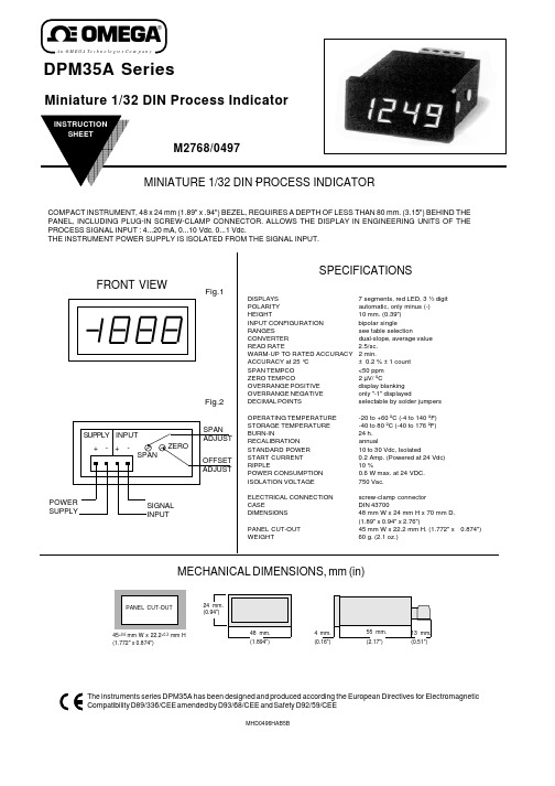
An OMEGA Te c h n o l o g ie s Co m p a n yMECHANICAL DIMENSIONS, mm (in)45+0.6 mm W x 22.2+0.3 mm H (1.772" x 0.874")MHD0496HAB5BDPM35A SeriesMiniature 1/32 DIN Process IndicatorFeatures a decimal point that can be set independently of signal range.For instance : 1 Vdc. signal on a ±2 Vdc meter can be displayed as 1.000, 10.00, 100.0, or 1000 for different engineering units. (in this example 1.000 V 10.00 mA.100.0% or 1000 mV)Fig.4a b c1 XX . X 1X . XX 1 . XX XDecimal pointposition Close Solder PadDisplay Board Components ViewDECIMAL POINT SELECTIONSignal Input Impedance ΩClose Jumpers0/4...20mA 182 1 & 20/10...50mA 68 1 & 30...2/10Vdc 200 K 10...10/200Vdc1 MNone*lower table, in function of signal input.Offset course : from -1000 to +1000To know the maximum negative Offset value, according to the Span value to be displayed apply this formula :((R3/S3) x S1) -1000.Span course for signal input :in Current, minimum 100 counts and maximum 3000 countsin Voltage, minimum 100 counts and maximum 2000 counts*Standard signal input for all orders unless specified otherwise.Display is adjusted to read 100.0WARRANTY/DISCLAIMEROMEGA warrants this unit to be free of defects in materials and workmanship and to give satisfactory service for a period of 13 months from date of purchase.OMEGA Warranty adds an additional one (1) month grace period to the normal one (1) year product warranty to cover handling and shipping time. This ensures that OMEGA's customers receive maximum coverage on each product. If the unit should malfunction, it must be returned to the factory for evaluation. OMEGA's Customer Service Department will issue an Authorized Return (AR)number immediately upon phone or written request. Upon examination by OMEGA, if the unit is found to be defective it will be repaired or replaced at no charge. However, this WARRANTY is VOID if the unit shows evidence of having been tampered with or shows evidence of being damaged as a result of excessive corrosion; or current; heat; moisture or vibration; improper specification; misapplication; misuse or other operating conditions outside of OMEGA's control. Components which wear or which are damaged by misuse are not warranted. These include contact points, fuses and triacs..OMEGA is pleased to offer suggestions on the use of its various products.However OMEGA neither assumes responsability for any omissions or errors nor assumes liability for any damages that result from the use of its products in accordance with information provided by OMEGA, either verbal or written.OMEGA only warrants that the parts manufactured by it will be as specified and free of defects. OMEGA MAKES NO OTHER WARRANTIES OR REPRE-SENTATIONS OF ANY KIND WHATSOEVER, EXPRESSED OR IMPLIED, EX-CEPT THAT OF TITLE AND ALL IMPLIED WARRANTIES INCLUDING ANY WARRANTY OF MERCHANTABILITY AND FITNESS FOR A PARTICULAR PUR-POSE ARE HEREBY DISCLAIMED.LIMITATION OF LIABILITY: The remedies of purchaser set forth herein are exclusive and the total liability of OMEGA with respect to this order, whether based on contract, warranty, negligence, indemnification, strict liability or otherwise, shall not exceed the purchase price of the component upon which liability is based. In no even shall OMEGA be liable for consequential,incidental or special damages.CONDITIONS: Equipment sold by OMEGA is not intended to be used, nor shall it be used:(1) as a "Basic Component" under 10 CFR 21 (NRC), used in or with any nuclear installation or activity; or (2) in medical applications or used on humans. Should any Product(s) be used in or with any nuclear installation or activity, medical application, used in humans, or misused in any way. OMEGA assumes no responsibility as set forth in our basic WARRANTY/DISCLAIMER language, and, additionally, purchaser will indemnify OMEGA and hold OMEGA harmlees from any liability or damage whatsoever arising out of the use of the Product(s) in such a manner.Servicing USA and Canada: Call OMEGA Toll FreeUSA CanadaOne Omega Drive, Box 4047976 BergarStamford, CT 06907-0047Laval (Quebec) H7L 5A1Telephone: (203) 359-1660Telephone: (514) 856-6928FAX: (203) 359-7700FAX: (514) 856-6886Sales Service: 1-800-826-6342 / 1-800-TC-OMEGA SM Customer Service: 1-800-622-2378 / 1-800-622-BEST SM Engineering Service: 1-800-872-9436 / 1-800-USA-WHEN SMTELEX: 996404 EASYLINK: 62968934 CABLE: OMEGAServicing Europe: One OMEGA Drive, River BendThecnology CentreNorthbank, Irlam, ManchesterM44 5EX , EnglandTelephone: 44 (161) 777-6611 FAX: 44 (161) 777-6622RETURN REQUESTS / INQUIRIESDirect all warranty and repair requests/inquiries to the OMEGA ENGINEERING Customer Service Department. BEFORE RETURNING ANY PRODUCT(S) TO OMEGA, PUR-CHASER MUST OBTAIN AN AUTHORIZED RETURN (AR) NUMBER FROM OMEGA'S CUSTOMER SERVICE DEPARTMENT (IN ORDER TO AVOID PROCESSING DELAYS).The assigned AR number should then be marked on the outside of the return package and on any correspondence.FOR WARRANTY RETURNS, please have the following information available BE-FORE contacting OMEGA:1.P.O. number under which the product was PURCHASED.2.Model and serial number of the product under warranty, and3.Repair instructions and/or specific problems relative to the product.FOR NON-WARRANTY REPAIRS, consult OMEGA for current repair charges. Have the following information available BEFORE contacting OMEGA:1.P.O. number to cover the COST of therepair,2.Model and serial number of product, and3.Repair instructions and/or specificproblems relative to the product.OMEGA's policy is to make running changes, not model changes, whenever an improve-ment is possible. This affords our customers the latest in technology and engineering.OMEGA is a registered trademark of OMEGA ENGINEERING, INC.© Copyright 1998 OMEGA ENGINEERING, INC. All rights reserved. This documentation may not be copied, photocopied, reproduced, translated, or reduced to any electronic medium or machine-readable form, in whole or in part, without prior written consent of OMEGA ENGINEERING, INC.ADJUSTMENT AND CALIBRATION PROCEDUREDetermine the lowest input (S1); highest input (S2); lowest reading (R1) and highest reading (R2).S3 = S2 - S1R3 = R2 - R11.-Select the Signal Input type installing the Jumpers according to Table2.2.-Connect a calibrator to the signal input terminals.3.-Power up the instrument with the appropriate power supply.4.-Adjust the calibrator until it generates 0 mA. or 0 Vdc.5.-Turn the "ZERO" trimmer (P1) until the display shows "0000".6.-Adjust the calibrator until it generates the S3 value (difference between the highest and lowest signal).7.-Turn the "SPAN" trimmer (P2) until the display shows the R3 value (difference between the highest and lowestreading).The adjustment procedure is finished, but if the lowest signal is different of 0 then follows with the next point.8.-Adjust the calibrator until it generates the low signal S1. (i.e. 4 mA).9.-Turn the "ZERO" trimmer (P1) until the display shows the lowest reading R1. The reading for lowest signalcan be modified as much times as wanted. The value of R3 will not be affected.10.-Close the jumper for the decimal point, according to the required decimals, see table 1.Example :Signal Input : 4...20 mA; Display Reading : 0...125.0Determine the value of S3 and R3.S3 = 20-4 = 16 mA R3 = 1250-0 = 12501.-Close Jumpers 1 &2.2.-Connect the calibrator and power up the instrument.3.-Adjust the calibrator at 0 mA and turn the trimmer P1 until the display shows "0000"4.-Adjust the calibrator at 16 mA and turn the trimmer P2 until the display shows "1250"5.-Adjust the calibrator at 4 mA and turn the trimmer P1 until the display shows "0000"6.-Close the Solder Pad "a".GENERAL CONSIDERATIONSINSTALLATIONPRECAUTIONS.- The installation and the future use of this unit must be done by suitable qualified personnel. The unit has not DC(mains) switch, neither internal protection fuse, it will be in operation as soon as power is connected. The installation mustincorporate an external mains switch with a protection fuse and also the necessary devices to protect the operator andthe process when using the unit to control a machine or process where injury to personnel or damage to equipment orprocess, may occur as a result of failure of the unit.SAFETY PRESCRIPTIONS.- The unit has been designed and tested under UNE 20553 rules and is delivered in good condition. This data sheet contains useful information for electrical connections. Do not make wiring signal changes or connections when power is applied to the unit. Make signal connections before power is applied and, is reconnection is required, disconnect the DC (mains)power before such wiring is attempted.Install the unit in a places with a good ventilation to avoid the excessive heating. And far from electrical noise source or magnetic field generators such as power relays, electrical motors, speed controls etc...The unit cannot be installed in open places. Do not use until the installation is finished.POWER SUPPLY.- The power supply must be connected to the adequate terminals (see the connection instructions). The characteristics of the power supply are showed on the side label. Please make sure that the unit is correctly connected to a power supply of the correct voltage and frequency.Do not use other power supply otherwise permanent damage may be caused to the unit. Do not connect the unit to power sources heavily loaded or to circuits which power loads in cycle ON-OFF or to circuits which power inductive loads.WARNING.- The power supply is dc voltage, be careful with the polarity indicated for each terminal.SIGNAL WIRING.- Certain considerations must be given when install the signal input wires. If the wires are longs can act like an antenna and introduce the electrical noise to the unit, therefore :Do not install the signal input wires in the same conduit with power lines, heaters, solenoids, SCR controls etc...and always far from these elements.SAFETY CONSIDERATIONSPRESCRIPTIONS.- Before starting any operation of adjustment, replacement, maintenance or repair, the unit must be disconnected from any kind of power supply.Keep the unit clean , to assure good functioning and performance.To prevent electrical or fire hazard, do not expose the unit to excessive moisture.Do not operate the unit in the presence of flammable gases or fumes, such an environment constitutes a definite safety hazard. The unit is designed to be mounted in a metal panel.If the unit shows signs of damage, or is not able to show the expected measures, or has been stored in a bad conditions or a protection failure can occur, then do not attempt to operate and keep the unit out of service.IN CASE OF FIRE1.- Disconnect the unit from the power supply.2.- Give the alarm according to the local rules.3.- Switch off all the air conditioning devices.4.- Attack the fire with carbonic snow, do not use water in any case.WARNING : In closed areas do not use systems with vaporized liquids.Signal Input :Lowest (S1) = 4 mAHighest (S2) =20 mAReading :Lowest (R1) =200Highest (R2) =1700S3 = S2 - S1 = 20 - 4 =16 mA R3 = R2 - R1= 1700 - 200 = 1500Signal Input 4...20 mAEXAMPLES OF ADJUSMENT AND CALIBRATION PROCEDUREA.- Without offsetSignal Input :Lowest (S1) =0 mAHighest (S2) =20 mAReading :Lowest (R1) =0Highest (R2) = 1700S3 = S2 - S1=20 - 0 = 20 mA R3 = R2 - R1=1700 - 0 = 17001700200020 mAD i s p l a yInput Signal Input 0...20 mA Display Reading 0 (1700)B.- With Negative OffsetSignal Input :Lowest (S1) = 4 mAHighest (S2) =20 mAReading :Lowest (R1) =0Highest (R2) =1700S3 = S2 - S1= 20 - 4 =16 mA R3 = R2 - R1= 1700 - 0 =1700Signal Input 4...20 mA Display Reading 0 (1700)C.- With Positive Offset。