锥形磨浆机使用说明书
磨浆机安全操作规程范本

磨浆机安全操作规程范本第一章总则第一条为了保证磨浆机的安全运行,保护操作人员的生命财产安全,规范磨浆机的使用和操作,制定本安全操作规程。
第二条本规程适用于磨浆机的操作和维护保养人员,必须依据国家、行业以及企业相关安全标准执行。
第三条磨浆机操作人员必须严格遵守本规程的规定,执行操作规程,做到安全第一,预防为主,事故预防和安全工作要深入到各个环节和工作当中。
第二章安全操作规范第四条人员要求1. 磨浆机操作人员必须经过相关的安全培训,并持有相关的操作证书;2. 操作人员必须了解磨浆机的结构、性能和工作原理,并熟悉磨浆机的使用方法;3. 操作人员必须严格遵守操作规程,不得擅自修改设备参数;4. 不得将磨浆机交给未经培训和未持证人员操作。
第五条环境要求1. 磨浆机应放置在干燥、通风良好的地方,远离易燃、易爆、有腐蚀性的物质;2. 磨浆机周围应保持整洁,无杂物阻挡;3. 磨浆机所在区域应配备相关的应急设备和消防器材。
第六条使用要求1. 在使用磨浆机之前,应检查设备的电源是否正常,电源线是否有损坏;2. 磨浆机启动前,应检查磨浆机的各个部位是否安装牢固,所有螺钉是否拧紧;3. 使用磨浆机时,操作人员应站在机器侧面,远离磨浆机的转动部位;4. 严禁使用手进行清扫或接触磨浆机正在运转的部位;5. 在磨浆机的工作过程中,不得随意调整磨浆机的电源;6. 磨浆机停机后,应切断电源并进行清洁。
第七条维护保养要求1. 磨浆机的维护保养应按照设备说明书和厂家要求进行;2. 磨浆机的定期维护保养应由具备相应资质的专业人员进行;3. 磨浆机使用过程中发现任何异常情况,应立即停机检修,并通知维修人员进行维修;4. 磨浆机故障维修应由专业人员进行,不得擅自拆卸、修理磨浆机。
第八条急救措施1. 在操作磨浆机时,如发生触电、碰伤、机械伤害等意外事故,应立即停机,并进行紧急救治;2. 如发生火灾等突发事件,应立即切断电源,并采取相应的灭火措施,同时报警求助。
磨浆机安全操作规程
磨浆机安全操作规程磨浆机是一台常见的机械设备,广泛应用于建筑、化工、冶金等许多行业。
在磨浆机使用过程中,安全是至关重要的。
为了保障人员的安全,以下是磨浆机的安全操作规程:一、机器操作前的准备工作1. 工作人员在操作磨浆机前应了解磨浆机的工作原理、结构、安全操作规程等,确保自己能独立进行操作。
2. 磨浆机应放置在平整地面上,并且固定牢靠,以保证磨浆机在工作中不会发生剧烈晃动、倾斜等现象。
3. 工作人员应穿戴防护服和工作鞋,并且不允许穿戴过于宽松的衣服,以防缠住磨浆机的旋转部件。
4. 机器内部应没有无关物品,然后上电,通过监听、观察等方式检查设备是否正常启动,是否存在不正常声响,检查电缆是否破损,保证人员安全。
二、机器操作过程中的注意事项1. 在磨浆机运作前,应先将水口接上主机,然后开始给磨浆机加水,保证磨浆机内部润滑充足,减缓磨损,在设备稳定运行中。
2. 操作人员不应将手伸入磨浆机内部,不应以身体相近方式解决机器故障。
3. 磨浆机运转过程中,不应以任何方式干扰机器的正常运行。
如果机器出现了不正常的现象和声响,应立即停机,排除故障;机器内部的水应及时放光,停机时应保证水自然流干,切断电源。
4. 运行磨浆机时,应根据工种、工艺标准,正确选择转速和负荷,保证机器的正常运行。
5. 在清理或维修磨浆机时,应切断电源并贴有警示标志,防止其他人员误操作。
维修时间内,不得擅自启动、加工等任何行动。
三、机器停机后的注意事项1. 磨浆机停机后,应及时去除机器内残留的砂浆和水,然后将机器放置在干燥通风处。
2. 维护人员应定期检查并更换磨浆机内部的易损件和电线电缆,保证机器的正常运行。
3. 工作人员应始终保持安全意识,熟练掌握磨浆机的安全操作规程,严格遵守相关的管理规定,防止意外事故的发生。
总之,磨浆机的安全操作规程需要从机器操作前的准备工作、机器操作过程中的注意事项以及机器停机后的注意事项等方面进行严格规范。
只有确保机器的安全操作,并严格执行操作规程才能真正保证人员的安全。
磨浆机安全操作规程
磨浆机安全操作规程磨浆机是一种常用于工业生产中的设备,其作用是将原料磨碎成浆状物。
为了确保工作安全,减少事故的发生,下面是磨浆机的安全操作规程,供您参考。
一、磨浆机的基本知识1. 磨浆机是一种旋转设备,主要包括电动机、磨盘、导杆、出浆口等部件。
2. 磨浆机运行时,磨盘会以较高速度旋转,所以操作时要保持警惕,避免手部或身体接近磨盘。
3. 磨浆机需要定期进行维护保养,以确保设备的正常运行和安全性能。
二、磨浆机的安全操作规程1. 操作前的准备:(1)操作人员应穿戴好个人防护装备,包括安全帽、防护眼镜、工作服等。
(2)确认磨浆机的电源接地情况良好,电气设备无损坏。
(3)检查磨盘和导杆是否完好无损,有无异物附着,磨盘是否松动。
2. 启动磨浆机:(1)确认磨浆机的开关处于关闭状态。
(2)接通电源,打开磨浆机的电源开关。
(3)按下启动按钮,等待磨盘达到正常工作速度。
(4)启动磨浆机后,应立即离开工作区域,避免站在磨盘旁边。
3. 操作过程中的注意事项:(1)不得用手或其他物体接触正在运转的磨盘。
(2)不得将有害物质投入磨浆机内。
(3)不得将过大的物块投入磨浆机内,以免堵塞设备。
(4)对磨浆机进行定期巡视,及时发现问题并进行处理。
4. 停止磨浆机:(1)工作结束后,应先按下停机按钮,等待磨盘停止旋转。
(2)关闭磨浆机的电源开关。
(3)在清理和维护磨浆机时,应先确保设备已彻底停止运转,并断开电源。
5. 紧急情况的处理:(1)如果发现磨浆机异常运转或其他紧急情况,应立即按下紧急停机按钮,并通知相关人员。
(2)经过专业人员检查后,方可重新启动设备。
6. 维护保养:(1)定期对磨浆机进行维护保养,包括清洁磨盘、检查磨盘和导杆的磨损情况,并及时更换。
(2)更换磨盘或导杆时,应使用专用工具进行操作,不得使用手动操作。
(3)定期对电气设备进行检查,确保电线电缆不受损坏。
以上就是磨浆机的安全操作规程的一些要点,希望能帮助您更安全地使用磨浆机。
锥形磨浆
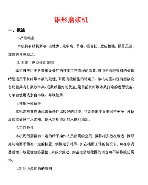
锥形磨浆机一、概述⒈产品特点本机具有结构紧凑,占地少、效率高、节电、噪音低、适应性强,操作灵活,维修方便等特点。
2.主要用途及适用范围本机可应用于各造纸设备厂的打浆工艺流程的需要,可用于各种浆料的处理,特别适用于长纤维木浆的处理,并配有疏解型的转定子。
该机与国内现有磨浆设备比较具有打浆效率高、成浆质量好的优点,是目前长纤维木浆打浆的理想设备。
可单台使用或多台串联、并联使用。
⒊使用环境条件本机需放置在通风采光条件比较好的环境,特别是地平面要保持干净,设备周边需做好下水沟槽,使水封处流出的水顺利排出。
⒋工作条件本机周围需留有一定的给予操作人员所需的空间,操作柜安放在墙边,锥形壳与墙面须留有一定的位置,供换定子时用。
如在楼面工作的情况下,可在水泥基础墩下放置橡胶防震垫,来减少振动,如基础承载稳固的话也可不放橡胶防震垫。
⒌对环境及能源的影响本产品为轴向进浆,径向上方出浆的一种卧式锥形打浆设备,锥形磨浆机只有一个轴向移动部分,即转子意味着间隙比较稳定,所以生产的纤维强度高,而且磨浆能耗低,针对长纤维木浆来说,相同打浆度条件下,抗张强度、耐破度、耐撕裂度等指标比目前国内磨浆设备有较大提高。
如达到相同抗张强度可以用较低的打浆度,可以节约电耗,以利脱水。
可节能20%~30%左右。
由于锥形面接触好,噪音低,相同打浆电流下噪音有明显的降低。
与国内同类打浆设备相比,噪音可降低20分贝左右。
⒍安全联轴器处为旋转部位,在开机时一定要装好防护罩;检修及更换定转子时必须使该机总电源切断后,方可进行检修操作。
二、结构特征与工作原理⑴本机是由机座、机壳、锥形壳、上盖、滑动套、主轴及动定齿圈组成,机座与机壳连接在一起。
定齿圈装在锥形壳与机壳之间,转盘装在主轴上,动齿圈固定在转盘上。
⑵本机由主要电动机经联轴器直接带动动齿圈旋转进行打浆。
进刀电机通过蜗杆、蜗轮减速器经联轴器驱动梯形丝杆与螺母套使主轴作轴向移动,从而调整动、定齿圈间隙。
ZJJ 锥形磨操作规程1
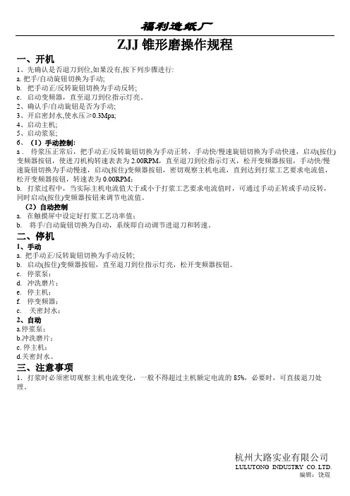
福利造纸厂ZJJ 锥形磨操作规程一、开机1、先确认是否退刀到位,如果没有,按下列步骤进行:a. 把手/自动旋钮切换为手动;b.把手动正/反转旋钮切换为手动反转;c.启动变频器,直至退刀到位指示灯亮。
2、确认手/自动旋钮是否为手动;3、开启密封水,使水压≥0.3Mpa;4、启动主机;5、启动浆泵;6、(1)手动控制:a . 待浆压正常后,把手动正/反转旋钮切换为手动正转,手动快/慢速旋钮切换为手动快速,启动(按住)变频器按钮,使进刀机构转速表表为2.00RPM,直至退刀到位指示灯灭,松开变频器按钮,手动快/慢速旋钮切换为手动慢速,启动(按住)变频器按钮,密切观察主机电流,直到达到打浆工艺要求电流值,松开变频器按钮,转速表为0.00RPM;b. 打浆过程中,当实际主机电流值大于或小于打浆工艺要求电流值时,可通过手动正转或手动反转,同时启动(按住)变频器按钮来调节电流值。
(2)自动控制a. 在触摸屏中设定好打浆工艺功率值;b.将手/自动旋钮切换为自动,系统即自动调节进退刀和转速。
二、停机1、手动a. 把手动正/反转旋钮切换为手动反转;b.启动(按住)变频器按钮,直至退刀到位指示灯亮,松开变频器按钮。
c.停浆泵;d.冲洗磨片;e.停主机;f.停变频器;c.关密封水;2、自动a.停浆泵;b.冲洗磨片;c. 停主机;d.关密封水。
三、注意事项1.打浆时必须密切观察主机电流变化,一般不得超过主机额定电流的85%,必要时,可直接退刀处理。
杭州大路实业有限公司LULUTONG INDUSTRY CO. LTD.编辑:饶琨。
自进料立式锥型磨 说明书

说明书自进料磨浆机所属技术领域本实用新型涉及造纸业使用的一种磨浆机,尤其是一种自进料的立式锥形磨浆机或是一种自进料的卧式锥形磨浆机,适合于高中低浓度的磨浆机,可用于各类机械制浆和后序打浆。
背景技术目前,造纸业使用的各种高中低浓磨浆机,均采用泵或喂料螺旋强制给料方式,动力消耗大,相对效率低,特别是高浓磨浆机,动力配备大,所玩需附属设备多,工艺也极为复杂,特别是在制浆中使用的磨浆机动力的配置在几千千瓦,很多企业无法安装和使用。
近几年来我国造纸行业发展迅猛,但磨浆设备仍然处于高能耗位子,特别是目前国家提倡节能降耗、清洁制浆,对设备提出了更高要求;很多磨浆机只能是低浓或高浓设备,并且市场上很多高浓磨浆机存在着高浓度进低浓度磨的状态,实际上与低浓磨浆机功效没有大的区别;而一些高浓磨浆机,动力配备大的惊人,且价格昂贵。
发明内容本实用新型的目的是要提供一种自进料锥形磨浆机,克服现有各种磨浆机功能单一、能耗偏高的不足。
本实用新型解决其技术问题所采用的技术方案是:本实用新型将现有卧式锥形磨浆机改为增加与磨浆转子相连并与其同轴同运行的进料螺旋,或将卧式锥形磨浆机改为立式锥形磨浆机,将进料口改为进料仓,并将锥形转子向上延伸,并在延伸处加进料螺旋,使进料螺旋与转子同步运行,形成向下的强大推力,完成自进料,磨浆机的定子和转子上的磨片分为三段三种刀形,底刀与飞刀之间的间隙由大到小,使浆料在进料螺旋的推动下直接进入磨浆机的破碎区、粗磨区和精精磨区;同时加大磨腔,并在磨腔中的轴段加拨浆叶片,使磨好的浆料迅速排出。
通过调整底刀与飞刀的间隙,采用传统的定子进退刀方式调整低刀与飞刀的间隙,也可采用调整转子的方式调整定刀与飞刀的间隙,从而达到控制磨浆扣解度的效果。
通过自进料螺旋、底刀与飞刀所产生的向下推力、离心力和重力使浆料完成向下运动的合力,确保了浆料流动,到磨腔后由拨浆叶片送出腔外。
这样,使这台磨具有了适合高中低浓度磨浆的能力。
本实用新型的有益效果是:由于增加了锥形和柱式两段进料螺旋,一是使浆料能自行进入磨浆机内,所以省去了为磨浆机供给浆料的装置,减化了工艺,同时节省了大量能耗,二是采用立式进料和磨片,充分利用了浆料的自身重力和磨浆机的飞刀与底刀对浆料形成的离心力和向下的推力,使浆料能顺利的通过磨区,进入磨腔后受拨浆叶轮和推动下迅速离开磨浆机。
JET PBF-1650D双面16ga盒子和盘式锥形磨刀机操作说明书

Operating Instructions and Parts ManualDual-Sided 16ga. Box and Pan Brake Model PBF-1650DJET427 New Sanford RoadLaVergne, Tennessee 37086 Part No. M-752130 Ph.: 800-274-6848 Edition 2 08/2018 Copyright © 2016 JET1.0 IMPORTANT SAFETYINSTRUCTIONSREAD ALL INSTRUCTIONS BEFORE USING THIS MACHINE.WARNING – To reduce the risk of injury:1. Read and understand the entire owner'smanual before attempting assembly or operation.2. Read and understand the warnings posted onthe machine and in this manual. Failure tocomply with all of these warnings may causeserious injury.3. Replace the warning labels if they becomeobscured or removed.4. This box and pan brake is designed andintended for use by properly trained and experienced personnel only. If you are notfamiliar with the proper and safe operation of abrake, do not use until proper training andknowledge have been obtained.5. Do not use this brake for other than its intendeduse. If used for other purposes, JET disclaimsany real or implied warranty and holds itselfharmless from any injury that may result fromthat use.6. Always wear ANSI Z87.1 approved safetyglasses or face shield while using this brake.(Everyday eyeglasses only have impact resistant lenses; they are not safety glasses.) 7. Before operating this machine, remove tie,rings, watches and other jewelry, and rollsleeves up past the elbows. Do not wear looseclothing. Confine long hair. Non-slip footwear oranti-skid floor strips are recommended.8. Wear ear protectors (plugs or muffs) if noisereaches unsafe levels.9. Do not operate this machine while tired or underthe influence of drugs, alcohol or any medication.10. Remove adjusting keys and wrenches. Form ahabit of checking to see that keys and adjustingwrenches are removed from the machine before turning it on.11. Keep safety guards in place at all times whenthe machine is in use. If removed for maintenance purposes, use extreme cautionand replace the guards immediately after completion of maintenance. 12. Check damaged parts. Before further use of themachine, a guard or other part that is damagedshould be carefully checked to determine that itwill operate properly and perform its intendedfunction. Check for alignment of moving parts,binding of moving parts, breakage of parts, mounting and any other conditions that mayaffect its operation. A guard or other part that isdamaged should be properly repaired or replaced.13. Provide for adequate space surrounding workarea and non-glare, overhead lighting.14. Keep the floor around the machine clean andfree of scrap material, oil and grease.15. Keep visitors a safe distance from the workarea. Keep children away.16. Make your workshop child proof with padlocks,master switches or by removing starter keys. 17. Give your work undivided attention. Lookingaround, carrying on a conversation and “horse-play” are careless acts that can result in seriousinjury.18. Maintain a balanced stance at all times so thatyou do not fall into the blade or other movingparts. Do not overreach or use excessive forceto perform any machine operation.19. Use recommended accessories; improperaccessories may be hazardous.20. Maintain tools with care. Keep blades sharp andclean for the best and safest performance.Follow instructions for lubricating and changingaccessories.21. Do not stand on the machine. Serious injurycould occur if the machine tips over.22. Remove loose items and unnecessary workpieces from the area before operating the machine.23. Do not use in dangerous environment. Do notuse machine in damp or wet location, or exposeto rain. Keep work area well lighted.24. Sheet metal stock has sharp edges; use cautionwhen handling to prevent cuts.25. Keep hands clear of bending area whileoperating.26. Do not exceed rated capacity of brake.27. The brake should be secured to floor withappropriate fasteners.Familiarize yourself with the following safety notices used in this manual:This means that if precautions arenot heeded, it may result in minor injury and/or possible machine damage.This means that if precautions arenot heeded, it may result in serious, or possibly even fatal, injury.SAVE THESE INSTRUCTIONS2.0 About this manualThis manual is provided by JET, covering the safe operation and maintenance procedures for a JET Model BPF-1650D Dual-Sided Box and Pan Brake. This manual contains instructions on installation, safety precautions, general operating procedures, maintenance instructions and parts breakdown. Your machine has been designed and constructed to provide consistent, long-term operation if used in accordance with the instructions as set forth in this document.This manual is not intended to be a guide to sheet metal bending, bend allowances, material choice, etc. Consult a machinery’s handbook and/or experienced users for such information. Whatever accepted methods or materials are used, always make personal safety a priority.If there are questions or comments, please contact your local supplier or JET. JET can also be reached at our web site: .Retain this manual for future reference. If the machine transfers ownership, the manual should accompany it. Read and understand the entire contents of this manual before attempting assembly oroperation! Failure to comply may cause serious injury!Register your product online - /us/en/service-and-support/warranty/registration/WARNING: This product can expose you to chemicals including lead which is known to the State of California to cause cancer and birth defects or other reproductive harm. For more information go to http://www.p65warnings.ca. gov.WARNING: Some dust, fumes and gases created by power sanding, sawing, grinding, drilling, welding and other construction activities contain chemicals known to the State of California to cause cancer and birth defects or other reproductive harm. Some examples of these chemicals are:• lead from lead based paint• crystalline silica from bricks, cement and other masonry products• arsenic and chromium from chemically treated lumberYour risk of exposure varies, depending on how often you do this type of work. To reduce your exposure to these chemicals, work in a well-ventilated area and work with approved safety equipment, such as dust masks that are specifically designed to filter out microscopic particles. For more information go to / and http:// /wood.3.0 Table of contentsSection Page1.0 IMPORTANT SAFETY INSTRUCTIONS (2)2.0 About this manual (3)3.0 Table of contents (4)4.0 Specifications for 16x50 Box and Pan Brake (5)4.1 Floor Diagram (5)5.0 Features and terminology (6)6.0 Setup and assembly (7)6.1 Unpacking and cleanup (7)6.2 Contents of shipping container (7)6.3 Tools required for assembly (7)6.4 Assembly (7)7.0 Operation (7)7.1 Finger spacing (7)7.2 Adjusting setback (7)7.3 Adjusting clamping pressure (8)7.4 Repeat bends (8)7.5 General procedure (8)8.0 User-maintenance (8)8.1 Lubrication (8)8.2 Additional servicing (8)9.0 Troubleshooting PBF-1650D Box and Pan Brake (8)10.0 Replacement Parts (8)10.1.1 BPF-1650D Box and Pan Brake – Exploded View (9)10.1.2 PBF-1650D Box and Pan Brake – Parts List (10)11.0 Warranty and service (12)4.0 Specifications for 16x50 Box and Pan BrakeModel Number ...................................................................................................................................... PBF-1650D Stock Number (752130)Materials:Frame .......................................................................................................................... welded steel plate/tubing Clamping fingers .............................................................................................................................. ground steel Clamping block ................................................................................................................. p recision ground steel Capacities:Bending length .......................................................................................................................... 50 in. (1270 mm) Maximum thickness, mild steel ................................................................................................... 16 ga. (1.5 mm) Bending angle .................................................................................................................................. 0 – 135 deg. Maximum beam lift ................................................................................................................ 1-13/16 in. (46 mm) Maximum box depth ................................................................................................................. 2.5 in. (63.5 mm) Minimum flange in capacity material ............................................................................................. 0.4 in. (10mm) Nose angle (upper fingers) ...................................................................................................................... 42 deg. Nose radius ............................................................................................................................. 1/32 in. (0.79 mm) Number of fingers ............................................................................................................ ......12 upper, 12 lower Finger widths ........................................................... 1, 1-1/8, 1-3/8, 1-1/2, 1-3/4, 2, 3, 4, 6, 7-3/4, 10, 10-5/8 in. Weights:Net ............................................................................................................................................... 772 lb (350 kg) Shipping ....................................................................................................................................... 849 lb (385 kg) Dimensions:Height, floor to working surface ............................................................................................ 35-1/2 in. (902 mm) Shipping (LxWxH) .......................................................................... 67-3/8 x 28 x 51-1/2 in. (171 x 71 x 131 cm) Assembled (LxWxH) ................................................................................... 63 x 38 x 45 in. (160 x 97 x 114 cm) The specifications in this manual were current at time of publication, but because of our policy of continuous improvement, JET reserves the right to change specifications at any time and without prior notice, without incurring obligations.L=length, W=width, H=height4.1 Floor DiagramFigure 15.0 Features and terminologyFigure 21. Clamping leaf2. Clamping fingers3. Clamping adjustment nut (x2)4. Stop bolt5. Setback locking screw (x2)6. Setback knob (x2)7. Bending leaf fingers8. Bending leaf9. Foot pedal for clamping 10. Foot pedal lock11. Leg extension (x2)12. Crown adjustment rod13. Air spring14. Grease fitting (x2)15. Stop collar16. Stop collar screw17. Eccentric disc6.0 Setup and assemblyRead and understand all assembly instructions before attempting assembly. Failure to comply may cause serious injury.6.1 Unpacking and cleanupInspect contents of shipping container for shipping damage. Report any damage to your distributor. Remove all contents from carton, and compare to the contents list in this manual. Report any part shortages to your distributor.Do not discard carton or packing material until machine is assembled and working properly. Exposed metal areas may have a rust protectant applied. Remove this with a soft rag and solvent such as kerosene. (Do not use gasoline, paint thinner, acetone, etc., as these will damage painted surfaces.)6.2 Contents of shipping container1 Box and Pan Brake2 Support legs with screws1 Instructions and Parts Manual (not shown)1 Warranty Card (not shown)6.3 Tools required for assembly8mm hex key6.4 AssemblyNumbers in parentheses refer to items in Figure 2. 1. Remove any straps or screws securing thebrake, and raise machine using properly ratedlifting equipment. See Figure 3 for lifting strapplacement.Figure 3Continue to stabilize machine while installing support legs. 2. Attach the two leg extensions (11) with theprovided socket head screws and flat washers. 3. Secure brake to floor using lag screws or similarsystem. See diagram, Figure 1. Also level thebrake; use shims if needed.4. The stop collar screw (16) has been tightenedfor shipping purposes. This screw must beloosened to allow clamping machine adjustments.7.0 OperationNumbers in parentheses refer to items in Figure 2. 7.1 Finger spacingUpper (2) and lower (7) fingers are mounted on T-nuts that slide within the underlying channel. Remove fingers by removing the screw(s); or reposition fingers at any place along the beam by loosening screw and sliding the T-nuts. Firmly tighten screws on fingers before operating.7.2 Adjusting setbackThe bending leaf lower fingers (7) must be adjusted for proper clearance or “setback” (A, Figure 3) based on material thickness (B, Figure 3). Generally, setback for material within four gauges of capacity should be twice the thickness of material. For lighter gauges, use 1-1/2 times the material thickness. Consult a machinery handbook for bend allowances.Figure 31. Loosen setback locking screws (5).2. Rotate setback knobs (6) in equal amounts(clockwise decreases distance). Refer to adjoining scale, marked with 0.002-inch graduations.Note: When increasing distance (counter-clockwise), you may have to pull back slightlyon the bending leaf to take up any backlash.3. Bring clamping leaf into position and checksetback.4. Repeat above steps until proper distance isachieved.5. Tighten locking screws (5).If a crown develops in the material, this can be adjusted out by loosening or tightening the hex nuts on the crown adjustment rod (12). Note: This rod has been correctly set by the manufacturer and should only be adjusted when needed.7.3 Adjusting clamping pressure Clamping pressure may vary depending upon material gauge. Pressure should be great enough to hold material securely, but not so much that it becomes difficult to clamp.Rotate clamping adjustment nuts (3) equally to set clamping pressure. Proper adjustment will allow foot pedal (9) to be locked (10).7.4 Repeat bendsLoosen stop collar screw (16) and adjust stop bolt (4) to limit swing of bending leaf. Retighten screw (16).7.5 General procedure1. Adjust upper and/or lower fingers for width ofmaterial and type of bend.2. Adjust for setback and clamping pressure.3. Position stop bolt if needed.4. Align material in machine and press foot pedaluntil it locks.5. Raise bending leaf to desired angle.6. Lower bending leaf and press foot pedal lock torelease material.8.0 User-maintenance Periodically wipe down machine with a soft rag. Keep upper and lower fingers clean and clear of debris. Apply light coat of SAE30 oil to upper and lower fingers.Periodically check tightness of fasteners.8.1 LubricationDaily insert a multi-purpose grease into the two fittings (14).Lightly apply grease to pivot points around machine, such as setback rods and eccentric disc.Apply light coat of SAE30 oil to all machined (unpainted) parts when not in use, to inhibit rust. 8.2 Additional servicingAny additional servicing should be performed by an authorized service technician.9.0 Troubleshooting PBF-1650D Box and Pan Brake Symptom PossibleCause CorrectionBends created with great difficulty.Machine capacity exceeded. Use material within capacity. Incorrect setback. Increase setback.Clamping leaf will not clamp properly.Improper adjustment.Decrease distance between fingers andbeam.Clamping not even across width. Rotate adjustment nuts equal amount.Bend radius not consistent across material.Machine capacity exceeded. Use material within capacity.Bending leaf edge not parallel to fingers. Adjust bending leaf equally on both ends. Bending leaf has crown. Correct with crown adjustment rod.10.0 Replacement PartsReplacement parts are listed on the following pages. To order parts or reach our service department, call 1-800-274-6848 Monday through Friday, 8:00 a.m. to 5:00 p.m. CST. Having the Model Number and Serial Number of your machine available when you call will allow us to serve you quickly and accurately.Non-proprietary parts, such as fasteners, can be found at local hardware stores, or may be ordered from JET. Some parts are shown for reference only, and may not be available individually.10.1.1 BPF-1650D Box and Pan Brake – Exploded View10.1.2 PBF-1650D Box and Pan Brake – Parts ListIndex No Part No Description Size Qty1 ................ H40-210 .................... Adjusting Nut ........................................................... .. (2)2 ................ PBF1650D-02 ........... Clamping Leaf. ........................................................ .. (1)3 ................ PBF1650D-03 ........... T-Nut ........................................................................ (48)4-1 ............. PBF1650D-04-1 ........ Upper Finger ............................................................ 1” .. (1)4-2 ............. PBF1650D-04-2 ........ Upper Finger ............................................................ 1-1/8” . (1)4-3 ............. PBF1650D-04-3 ........ Upper Finger ............................................................ 1-3/8” . (1)4-4 ............. PBF1650D-04-4 ........ Upper Finger ............................................................ 1-1/2” . (1)4-5 ............. PBF1650D-04-5 ........ Upper Finger ............................................................ 1-3/4” . (1)4-6 ............. PBF1650D-04-6 ........ Upper Finger ............................................................ 2” .. (1)4-7 ............. PBF1650D-04-7 ........ Upper Finger ............................................................ 3” .. (1)4-8 ............. PBF1650D-04-8 ........ Upper Finger ............................................................ 4” .. (1)4-9 ............. PBF1650D-04-9 ........ Upper Finger ............................................................ 6” .. (1)4-10 ........... PBF1650D-04-10 ...... Upper Finger ............................................................ 7-3/4” . (1)4-11 ........... PBF1650D-04-11 ...... Upper Finger ............................................................ 10” (1)4-12 ........... PBF1650D-04-12 ...... Upper Finger ............................................................ 10-5/8” .. (1)5 ................ TS-1505021 .............. Socket Head Cap Screw ......................................... M10x20 .. (66)6 ................ PBF1650D-06 ........... Clamping Block ........................................................ .. (1)7 ................ PBF1650D-07 ........... Adjusting Nut Spring ................................................ .. (2)8 ................ TS-155011 ................ Flat Washer ............................................................. 20mm . (6)9 ................ PBF1650D-09 ........... Grease Fitting .......................................................... M8x1 .. (2)10 .............. H40-227 .................... Bushing .................................................................... .. (2)11 .............. H40-226 .................... Flat Washer ............................................................. 30 . (2)12 .............. H40-209 .................... Bending Leaf Pin ..................................................... .. (1)13 .............. TS-1505051 .............. Socket Head Cap Screw ......................................... M10x35 . (1)14 .............. H40-204 .................... Stop Collar ............................................................... .. (1)15 .............. TS-1540071 .............. Hex Nut .................................................................... M10 . (1)16 .............. TS-1505061 .............. Socket Head Cap Screw ......................................... M10x40 . (1)17 .............. PBF1650D-17 ........... Leg ........................................................................... .. (2)18 .............. BPF1240-18 .............. Ext. Retaining Ring .................................................. 25mm .. (13)19 .............. H40-208 .................... Leg Pin .................................................................... .. (3)20 .............. TS-1505041 .............. Socket Head Cap Screw ......................................... M10x30 . (4)21 .............. H40-217-3G .............. Extension Bracket .................................................... .. (2)22 .............. PBF1650D-22 ........... Disc Spring .............................................................. Ø40xø20x1mm . (4)23 .............. H40-205 .................... Rod .......................................................................... .. (2)24 .............. H40-206 .................... Foot Pedal Lever ..................................................... .. (4)25 .............. H40-207.................... Lever Pin .................................................................. .. (4)26 .............. PBF1650D-26 ........... Foot Pedal ............................................................... .. (1)27 .............. H40-402 .................... Tread Plate Rubber ................................................. .. (1)28 .............. H40-211 .................... Roll Pin .................................................................... .. (1)29 .............. BPF1240-29 .............. Ext. Retaining Ring .................................................. 10mm . (2)30 .............. H40-213.................... Foot Pedal Lock ....................................................... .. (1)31 .............. BPF1240-31 .............. Spring Pin ................................................................ 8x50mm (1)32 .............. TS-1550061 .............. Flat Washer ............................................................. 8mm (1)33 .............. H40-212 .................... Pedal Lock Spring ................................................... .. (1)34-1 ........... PBF1650D-34-1 ........ Lower Finger ............................................................ 1” .. (1)34-2 ........... PBF1650D-34-2 ........ Lower Finger ............................................................ 1-1/8” . (1)34-3 ........... PBF1650D-34-3 ........ Lower Finger ............................................................ 1-3/8” . (1)34-4 ........... PBF1650D-34-4 ........ Lower Finger ............................................................ 1-1/2” . (1)34-5 ........... PBF1650D-34-5 ........ Lower Finger ............................................................ 1-3/4” . (1)34-6 ........... PBF1650D-34-6 ........ Lower Finger ............................................................ 2” .. (1)34-7 ........... PBF1650D-34-7 ........ Lower Finger ............................................................ 3” .. (1)34-8 ........... PBF1650D-34-8 ........ Lower Finger ............................................................ 4” .. (1)34-9 ........... PBF1650D-34-9 ........ Lower Finger ............................................................ 6” .. (1)34-10 ......... PBF1650D-34-10 ...... Lower Finger ............................................................ 7-3/4” . (1)34-11 ......... PBF1650D-34-11 ...... Lower Finger ............................................................ 10” (1)34-12 ......... PBF1650D-34-12 ...... Lower Finger ............................................................ 10-5/8” .. (1)35 .............. BPF1240-31 .............. Spring Pin ................................................................ 8x50mm (2)37 .............. PBF1650D-37 ........... O-Ring ..................................................................... 25x3.55mm . (2)38 .............. PBF1650D-38 ........... Setback Rod ............................................................ .. (2)Index No Part No Description Size Qty39 .............. PBF1650D-39 ........... Setback Knob .......................................................... .. (2)40 .............. PBF1650D-40 ........... Operating Handle .................................................... .. (2)41 .............. PBF1650D-41 ........... Adjusting Rod .......................................................... .. (1)42 .............. PBF1650D-42 ........... Bending Leaf ........................................................... .. (1)43 .............. TS-1550111 .............. Flat Washer ............................................................. 20 . (2)44 .............. TS-2310201 .............. Hex Nut .................................................................... M20 . (2)45 .............. TS-2228161 .............. Hex Cap Screw ........................................................ M8x16 (2)46 .............. PBF1650D-46 ........... Fixing Plate .............................................................. .. (1)47 .............. PBF1650D-47 ........... Air Spring ................................................................. .. (1)48 .............. TS-2211451 .............. Hex Cap Screw ........................................................ M12x45 . (2)49 .............. TS-2311121 .............. Hex Nut .................................................................... M12 . (2)50 .............. PBF1650D-50 ........... Eccentric Holder ...................................................... .. (1)51 .............. TS-155011 ................ Flat Washer ............................................................. M20 . (2)52 .............. TS-1502021 .............. Socket Head Cap Screw ......................................... M5x10 (2)53 .............. PBF1650D-53 ........... Rubber Pad ............................................................. .. (2)54 .............. PBF1650D-54 ........... Bushing .................................................................... .. (4)55 .............. TS-1521031 .............. Socket Set Screw .................................................... M4x8 .. (2)56 .............. PBF1650D-56 ........... Scale ........................................................................ .. (2).................. LM000240 ................. ID/Warning Label, PBF-1650D (not shown) ............ .. (1).................. JET-165 ..................... JET Logo (not shown) ............................................. 165x68mm .. (1)11.0 Warranty and serviceJET warrants every product it sells against manufacturers’ defects. If one of our tools needs service or repair, please contact Technical Service by calling 1-800-274-6846, 8AM to 5PM CST, Monday through Friday.Warranty PeriodThe general warranty lasts for the time period specified in the literature included with your product or on the official JET branded website.•JET products carry a limited warranty which varies in duration based upon the product. (See chart below) •Accessories carry a limited warranty of one year from the date of receipt.•Consumable items are defined as expendable parts or accessories expected to become inoperable within a reasonable amount of use and are covered by a 90 day limited warranty against manufacturer’s defects. Who is CoveredThis warranty covers only the initial purchaser of the product from the date of delivery.What is CoveredThis warranty covers any defects in workmanship or materials subject to the limitations stated below. This warranty does not cover failures due directly or indirectly to misuse, abuse, negligence or accidents, normal wear-and-tear, improper repair, alterations or lack of maintenance. JET woodworking machinery is designed to be used with Wood. Use of these machines in the processing of metal, plastics, or other materials outside recommended guidelines may void the warranty. The exceptions are acrylics and other natural items that are made specifically for wood turning. Warranty LimitationsWoodworking products with a Five Year Warranty that are used for commercial or industrial purposes default to a Two Year Warranty. Please contact Technical Service at 1-800-274-6846 for further clarification.How to Get Technical SupportPlease contact Technical Service by calling 1-800-274-6846. Please note that you will be asked to provide proof of initial purchase when calling. If a product requires further inspection, the Technical Service representative will explain and assist with any additional action needed.JET has Authorized Service Centers located throughout the United States. For the name of an Authorized Service Center in your area call 1-800-274-6846 or use the Service Center Locator on the JET website.More InformationJET is constantly adding new products. For complete, up-to-date product information, check with your local distributor or visit the JET website.How State Law AppliesThis warranty gives you specific legal rights, subject to applicable state law.Limitations on This WarrantyJET LIMITS ALL IMPLIED WARRANTIES TO THE PERIOD OF THE LIMITED WARRANTY FOR EACH PRODUCT. EXCEPT AS STATED HEREIN, ANY IMPLIED WARRANTIES OF MERCHANTABILITY AND FITNESS FOR A PARTICULAR PURPOSE ARE EXCLUDED. SOME STATES DO NOT ALLOW LIMITATIONS ON HOW LONG AN IMPLIED WARRANTY LASTS, SO THE ABOVE LIMITATION MAY NOT APPLY TO YOU.JET SHALL IN NO EVENT BE LIABLE FOR DEATH, INJURIES TO PERSONS OR PROPERTY, OR FOR INCIDENTAL, CONTINGENT, SPECIAL, OR CONSEQUENTIAL DAMAGES ARISING FROM THE USE OF OUR PRODUCTS. SOME STATES DO NOT ALLOW THE EXCLUSION OR LIMITATION OF INCIDENTAL OR CONSEQUENTIAL DAMAGES, SO THE ABOVE LIMITATION OR EXCLUSION MAY NOT APPLY TO YOU.JET sells through distributors only. The specifications listed in JET printed materials and on official JET website are given as general information and are not binding. JET reserves the right to effect at any time, without prior notice, those alterations to parts, fittings, and accessory equipment which they may deem necessary for any reason whatsoever. JET® branded products are not sold in Canada by JPW Industries, Inc.Product Listing with Warranty Period90 Days – Parts; Consumable items1 Year – Motors; Machine Accessories2 Year – Metalworking Machinery; Electric Hoists, Electric Hoist Accessories; Woodworking Machinery usedfor industrial or commercial purposes5 Year – Woodworking MachineryLimited Lifetime – JET Parallel clamps; VOLT Series Electric Hoists; Manual Hoists; Manual HoistAccessories; Shop Tools; Warehouse & Dock products; Hand Tools; Air ToolsNOTE: JET is a division of JPW Industries, Inc. References in this document to JET also apply to JPW Industries, Inc., or any of its successors in interest to the JET brand.。
磨浆机安全操作规程
磨浆机安全操作规程磨浆机是一种用于加工磨浆的机械设备,广泛应用于造纸、纺织、陶瓷等行业。
由于操作磨浆机涉及到较高的工作压力和旋转设备,存在一定的危险性。
为了确保工作安全,减少事故发生的可能性,下面为大家介绍磨浆机的安全操作规程。
一、操作前准备1. 从事磨浆机操作的人员必须经过培训,掌握磨浆机的工作原理、结构和操作方法,并具备相关的安全意识。
2. 在操作磨浆机之前,必须检查设备的工作状态,确保各部件完好无损,无松动现象,并进行必要的润滑、清洁和维护。
3. 确定操作区域没有杂物和其他人员,设置明确的警示标识和防护设施,如安全围栏、防护网等。
4. 在操作过程中,应穿戴符合安全要求的工作服和个人防护装备,如安全帽、耳塞、防护眼镜等。
二、操作过程中的安全措施1. 开机前,必须确认电源和主机的接地情况是否良好,确保设备安全可靠地接通电源。
2. 启动磨浆机之前,必须先进行试运转,确认设备运行平稳无震动、无异响,确保无异常情况后方可正常启动。
3. 在加工磨浆之前,必须先调整好磨浆机的工作参数,如进料量、浆料浓度、磨浆时间等。
同时,根据需要选择合适的磨具,确保磨浆过程的效果和质量。
4. 在磨浆过程中,严禁将手或其他物体伸入磨浆机内部。
如需调整设备或处理异常情况,必须先停机并切断电源,等待设备完全停止运行后方可进行操作。
5. 当磨浆机运行中出现异常情况,如异响、震动、工作压力变化等,应立即停机检查并处理故障,切勿强行继续操作,以免造成更大的安全隐患。
6. 加工磨浆期间,应时刻关注机器的运行状态和工作环境,确保其稳定工作。
如发现设备异常或有外来干扰,应及时采取措施解决。
7. 在磨浆完成后,必须停止磨浆机的运行,并切断电源。
清理设备内部时,应确保机器处于停止状态,并避免接触到旋转部件,防止意外伤害。
三、操作后的安全要求1. 在操作完成后,必须对设备进行清洁、维护和保养,包括清理残留物、润滑部件、检查电器设备等,确保设备处于良好的工作状态。
- 1、下载文档前请自行甄别文档内容的完整性,平台不提供额外的编辑、内容补充、找答案等附加服务。
- 2、"仅部分预览"的文档,不可在线预览部分如存在完整性等问题,可反馈申请退款(可完整预览的文档不适用该条件!)。
- 3、如文档侵犯您的权益,请联系客服反馈,我们会尽快为您处理(人工客服工作时间:9:00-18:30)。
主要性能 本机运转平稳、振动小、噪音低,与其他打浆设备相比噪音可低 20 分贝,节 能 20%~30%。成浆纤维强度高,针对长纤维木浆来说,打浆指标可提高 10%~ 30%。
四、使用、操作
1.使用前的准备和检查 ⑴开机前机壳及内外锥形齿圈部分是否冲洗干净,进出浆管上部各阀门是否转 动灵活,密封情况是否良好。 ⑵滑动套、轴承及螺杆处是否含油,各润滑点润滑情况是否良好。 ⑶检查起动电柜、电机及电气控制系统是否良好。
五、保养、维护
郑州运达造纸设备有限公司
4
⒈日常维护、保养 要经常进行设备维护保养、清洗工作,保持设备整洁,运行正常。特别是滑
动裸露处不得进水,要涂上润滑脂。维修工作只有在磨浆机所有电路、管路处于关 闭状况下才能进行。
⒉运行时的维护、保养 运行时对各润滑点要定期进行润滑,滑动套与机盖之间的滑动面,每周注润 滑脂一次,梯形螺杆每个月涂润滑脂一次,各滚动轴承每三个月加一次润滑脂,要 保证各油管畅通、无阻塞现象。 ⒊检修周期 ⑴各滚动轴承处每隔六个月清洗、检查、换油一次。 ⑵梯形螺杆处每隔六个月清洗、检查、换油一次。 ⑶滑动套与机盖之间的滑动面每隔六个月清洗、换油一次。 ⒋正常维修程序 当动、定齿圈的齿部磨损达 60~70%左右时,一般需要更换. ⒌长期停机时的维护、保养
阅读更详细的使用说明说,请登录
郑州运达造纸设备有限公司
5
⒋辅助装置的功能结构及其工作原理、工作特性 ⑴管路安装可根据使用单位的具体情况进行排列安装,在进出浆上均需设透 明管路,以观察浆流状态。进出管上还需设有隔膜式压力表以观察浆料进出压力变 化(出浆透明管附件可由制造厂提供图纸(见附图),用户自行配制)。 ⑵还需在进出浆回路内考虑装取样阀门,供运行中取样。
郑州运达圈的旋转打浆工作是由主电机通过联轴器带动来进行的,当 浆压力在许可范围内正常工作,浆压过低或过高会通过电器线路中的故障报警系统 发出信号、指令进给电动机退刀,使动、定齿圈脱离工作区。
⑵进给电机通过齿轮减速器、联轴器驱动梯形丝杆与螺母套,使主轴作轴向 移动,无故障报警系统,负载过大,保险销会剪断,保护电机不被损坏。
郑州运达造纸设备有限公司
2
由于锥形面接触好,噪音低,相同打浆电流下噪音有明显的降低。与国内同类 打浆设备相比,噪音可降低 20 分贝左右。
⒍安全 联轴器处为旋转部位,在开机时一定要装好防护罩;检修及更换定转子时必 须使该机总电源切断后,方可进行检修操作。
二、结构特征与工作原理
⒈总体结构及其工作原理、工作特性 ⑴本机是由机座、机壳、锥形壳、上盖、滑动套、主轴及动定齿圈组成,机 座与机壳连接在一起。定齿圈装在锥形壳与机壳之间,转盘装在主轴上,动齿圈固 定在转盘上。 ⑵本机由主要电动机经联轴器直接带动动齿圈旋转进行打浆。进刀电机通过蜗 杆、蜗轮减速器经联轴器驱动梯形丝杆与螺母套使主轴作轴向移动,从而调整动、 定齿圈间隙。 ⒉主要部件功能单元的结构、作用及其工作原理 ⑴锥形磨浆机主要由一付动、定齿圈组成,动、定齿圈均采用特种合金钢精密 铸造而成,由于锥形接触面好,经精加工后间隙及打浆比压控制稳定,打浆质量均 匀性好。 ⑵滑动套装在主轴上,在上盖与机座之间往复移动,滑动套用导键结合在上盖 上,锥形磨浆机的进退刀即滑动套的往复移动可由进刀电机通过蜗轮蜗杆减速器经 联轴器驱动梯形丝杆与螺母套使主轴作轴向移动。两联轴器凹槽中装有两根保险 销,超过负载后外径Φ31×0.5 的保险销断面会剪断,以保护进刀电机的安全。 ⒊各单元结构之间的机电联系,系统工作原理,故障报警系统
锥形磨浆机
使用说明书
一、概述 二、结构特征与工作原理 三、技术特征 四、使用、操作 五、保养、维护
目录
郑州运达造纸设备有限公司
1
一、概述
⒈产品特点 本机具有结构紧凑,占地少、效率高、节电、噪音低、适应性强,操作灵活, 维修方便等特点。 2.主要用途及适用范围 本机可应用于各造纸设备厂的打浆工艺流程的需要,可用于各种浆料的处理,特 别适用于长纤维木浆的处理,并配有疏解型的转定子。该机与国内现有磨浆设备比 较具有打浆效率高、成浆质量好的优点,是目前长纤维木浆打浆的理想设备。可单 台使用或多台串联、并联使用。 ⒊使用环境条件 本机需放置在通风采光条件比较好的环境,特别是地平面要保持干净,设备周 边需做好下水沟槽,使水封处流出的水顺利排出。 ⒋工作条件 本机周围需留有一定的给予操作人员所需的空间,操作柜安放在墙边,锥形壳 与墙面须留有一定的位置,供换定子时用。如在楼面工作的情况下,可在水泥基础 墩下放置橡胶防震垫,来减少振动,如基础承载稳固的话也可不放橡胶防震垫。 ⒌对环境及能源的影响 本产品为轴向进浆,径向上方出浆的一种卧式锥形打浆设备,锥形磨浆机只 有一个轴向移动部分,即转子意味着间隙比较稳定,所以生产的纤维强度高,而且 磨浆能耗低,针对长纤维木浆来说,相同打浆度条件下,抗张强度、耐破度、耐撕 裂度等指标比目前国内磨浆设备有较大提高。如达到相同抗张强度可以用较低的打 浆度,可以节约电耗,以利脱水。可节能 20%~30%左右。