光源控制程序
实验1.彩灯控制程序设计
实验1.彩灯控制程序设计这是一个彩灯控制程序的设计,通过控制程序,用户可以方便地控制彩灯的亮度和颜色,实现节能环保、舒适安全的效果。
一、需求分析本程序需要实现以下功能:1、控制彩灯亮度的调节;2、控制彩灯颜色的切换;3、自动切换彩灯颜色和亮度;4、控制彩灯的开关。
在这些基础上,设计出一个具有简洁美观的用户界面,操作灵活简单。
二、设计实现1、灯的颜色和亮度控制将彩灯的设置分为亮度和颜色两部分,通过按键来选择相应的模式,进入亮度调节模式,通过旋转旋钮选择亮度,亮度可以分为10个档次,分别为1-10,其中1为最暗,10为最亮,用户可以通过按下按键来确认亮度选择。
在颜色选择模式下,用户可以通过旋转旋钮选择颜色,彩灯颜色的选择可以分为7种基本颜色和一个自动变色模式,分别为红、橙、黄、绿、蓝、靛、紫和自动变化,用户可以通过按下按键来确认颜色选择。
2、彩灯自动切换在实现彩灯自动切换功能时,通过设定自动切换周期,每隔一段时间就会自动切换到下一个颜色或亮度档次,可以选定不同的模式,在模式选择模式下,本程序支持普通闪烁模式和呼吸模式。
在普通闪烁模式下,每隔一段时间就会闪烁一次,可以通过指定闪烁时间来控制闪烁的频率。
在呼吸模式下,灯的亮度会缓慢变化,通过调节时间间隔和变化速度来实现呼吸效果。
3、灯的开关用户可以通过按键实现灯的开关,按下开关键可以切换灯的状态,再次按下可以切换回原状态。
三、用户界面设计程序的用户界面需要简单明了,以方便用户操作。
整个界面分为两个部分,上部分用于显示当前程序的状态信息,包括当前亮度、当前颜色和自动切换时间,下方则是设置面板,用户可以通过操作按钮来调节亮度和颜色,并选择不同的自动切换模式。
程序使用字体和图标来标记各个按键的功能,清晰明了,可以让用户快速找到所需功能。
四、实验结果通过程序的设计实现,可以方便地控制彩灯的亮度和颜色,实现自动切换,控制灯的开关状态。
同时,用户界面简洁美观,操作灵活方便。
51单片机分组控制灯实验步骤
51单片机分组控制灯实验步骤以下是基于51 单片机实现分组控制灯实验的基本步骤:
1. 硬件准备:
- 51 单片机开发板
- 连接线
- 不同颜色的LED 灯(根据需要选择)
2. 连接电路:
- 将LED 灯连接到单片机的I/O 口,确保每个LED 灯与一个单独的I/O 口相连。
3. 软件编写:
- 使用C 语言或汇编语言编写单片机程序。
- 定义LED 灯对应的I/O 口。
- 创建一个延时函数,用于控制灯的闪烁时间。
- 编写主函数,根据需要进行分组控制。
- 遍历每个分组,将相应的I/O 口设置为高电平或低电平,以控制灯的亮灭。
4. 编译和下载程序:
- 使用相应的编译器将编写的程序编译成可执行的hex 文件。
- 使用下载工具将hex 文件下载到单片机中。
5. 运行和测试:
- 连接单片机开发板到电源,并运行程序。
- 观察LED 灯的状态,确保每个分组的灯按照预期进行控制。
单片机控制LED灯点亮(C语言)PPT课件

实验结果与数据分析
实验结果
实验结果包括LED灯的状态和控制程序的执行情况。如果程序运行正常,LED灯应该能够按照预期点 亮和熄灭。
数据分析
数据分析包括对实验结果的分析和对控制程序的优化。通过对实验结果的分析,我们可以了解程序的 正确性和性能,并根据需要进行优化。
THANKS
感谢观看
根据需要改变LED灯的状态; 通过循环实现LED灯的闪烁效果。
06
程序调试与实验结果
调试工具与调试方法
调试工具
常用的调试工具包括串口调试助手、 示波器、逻辑分析仪等。这些工具可 以帮助我们实时监控程序运行状态, 检查程序中的错误和异常。
调试方法
常用的调试方法包括单步调试、断点 调试和内存检查等。这些方法可以帮 助我们逐步跟踪程序的执行过程,定 位和修复程序中的问题。
片机速度快,但功耗较大。
单片机的应用
• 总结词:单片机广泛应用于各种领域,如智能仪表、工业控制、家用电器、通讯设备等。单片机可以实现各种 控制功能,如温度控制、湿度控制、压力控制等,同时也可以用于数据采集和处理。
• 详细描述:单片机作为一种微型化的计算机系统,具有广泛的应用领域。在智能仪表领域,单片机可以实现各种测量和控制功能,如温度、湿度、压力等参数的测量和控制。在工业控 制领域,单片机可以用于自动化生产线、机器人等设备的控制和监测。在家用电器领域,单片机可以用于电视、空调、洗衣机等设备的控制和智能化管理。在通讯设备领域,单片机可 以用于调制解调器、路由器等设备的控制和数据处理。此外,单片机还可以用于数据采集和处理,如声音、图像等数据的采集和处理。
ห้องสมุดไป่ตู้
实验环境与实验步骤
实验环境
实验环境需要包括单片机开发板、LED灯、电源等硬件设备和相应的软件环境。软件环境需要包括单片机开发工 具和C语言编译器等。
单片机PWM调光程序

单片机PWM调光程序一、概述PWM(Pulse Width Modulation,脉宽调制)是一种常用的调光技术,通过控制信号的脉冲宽度来调节输出电平的平均值,从而实现对光源亮度的调节。
本文将介绍如何编写单片机PWM调光程序,并提供一个基于XX单片机的示例代码。
二、硬件准备1. 单片机:XX单片机(型号)2. 光源:LED灯(型号)3. 光敏电阻:用于实时检测环境光强度的元件4. 电路连接:将单片机的PWM输出引脚连接到LED灯的控制引脚,将光敏电阻连接到单片机的模拟输入引脚三、软件设计1. 引入头文件:根据单片机型号,引入相应的头文件,例如"xx.h"。
2. 定义宏:定义LED灯的控制引脚和光敏电阻的模拟输入引脚。
3. 初始化:设置单片机的引脚模式和PWM参数,例如设置PWM频率、占空比等。
4. 光敏检测:通过模拟输入引脚读取光敏电阻的电压值,将其转换为环境光强度的数值。
5. PWM调光:根据光敏检测到的环境光强度数值,计算对应的PWM占空比,并将其输出到LED灯的控制引脚。
四、示例代码```c#include <xx.h> // 引入相应的头文件#define LED_PIN 1 // 定义LED灯的控制引脚#define LDR_PIN 2 // 定义光敏电阻的模拟输入引脚void init_pwm() {// 设置引脚模式为PWM输出pinMode(LED_PIN, PWM_OUTPUT);// 设置PWM参数pwmSetMode(PWM_MODE_MS);pwmSetClock(100); // 设置PWM频率为100HzpwmSetRange(1024); // 设置PWM占空比范围为0-1024 }int read_ldr() {// 读取光敏电阻的电压值int ldr_value = analogRead(LDR_PIN);// 根据电压值转换为环境光强度数值int light_intensity = map(ldr_value, 0, 1023, 0, 100);return light_intensity;}void adjust_brightness(int light_intensity) {// 根据环境光强度计算PWM占空比int pwm_duty_cycle = map(light_intensity, 0, 100, 0, 1023);// 输出PWM占空比到LED灯的控制引脚pwmWrite(LED_PIN, pwm_duty_cycle);}int main() {init_pwm(); // 初始化PWMwhile (1) {int light_intensity = read_ldr(); // 光敏检测adjust_brightness(light_intensity); // PWM调光}return 0;}```五、使用方法1. 将示例代码中的XX单片机型号替换为实际使用的单片机型号。
照明控制C语言程序
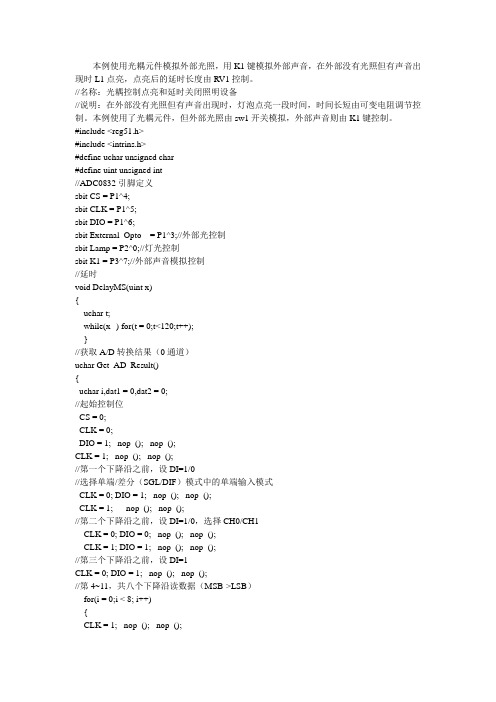
//名称:光耦控制点亮和延时关闭照明设备
//说明:在外部没有光照但有声音出现时,灯泡点亮一段时间,时间长短由可变电阻调节控制。本例使用了光耦元件,但外部光照由sw1开关模拟,外部声音则由K1键控制。
uchar Get_AD_Result()
{
uchar i,dat1 = 0,dat2 = 0;
//起始控制位
CS = 0;
CLK = 0;
DIO = 1;_nop_(); _nop_();
CLK = 1;_nop_(); _nop_();
//第一个下降沿之前,设DI=1/0
//选择单端/差分(SGL/DIF)模式中的单端输入模式
dat1 = dat1 << 1 |DIO;
}
//第11~18,共八个下降沿读数据(LSB->MSB)
for(i = 0;i < 8; i+&#(uchar) (DIO) << i );
CLK = 1; _nop_(); _nop_();
CLK = 0; _nop_(); _nop_();
sbit External_Opto = P1^3;//外部光控制
sbit Lamp = P2^0;//灯光控制
sbit K1 = P3^7;//外部声音模拟控制
//延时
void DelayMS(uint x)
{
uchar t;
while(x--) for(t = 0;t<120;t++);
}
//获取A/D转换结果(0通道)
}
灯光控制实验报告模板

灯光控制实验报告模板实验名称:灯光控制实验报告引言:灯光控制是现代电气工程中一项重要的技术,它在日常生活中起到重要作用。
本实验旨在研究灯光控制的基本原理和方法,探索不同控制方式对灯光亮度和颜色的影响。
通过实验观察、测量和分析,我们将了解到灯光控制的工作原理和应用。
实验目的:1. 了解灯光控制的基本原理和方法;2. 探究不同控制方式对灯光亮度和颜色的影响;3. 学会使用光度计和色度计测量灯光亮度和颜色。
实验设备:1. LED灯光源;2. 调光开关;3. 光度计和色度计;4. 电源;5. 连接线。
实验步骤:1. 将LED灯光源连接到电源,打开电源开关。
2. 使用调光开关调节灯光亮度,观察灯光的变化。
分别记录亮度和调光开关旋钮位置之间的关系。
3. 使用光度计测量不同亮度下的光照强度,并记录测量值。
4. 切换不同颜色的LED灯光源,重复步骤2-3,记录不同颜色灯光的亮度和光照强度数据。
5. 使用色度计测量不同颜色灯光的色温和色差,并记录测量值。
实验数据分析:1. 根据实验数据,绘制亮度与调光开关旋钮位置的关系曲线。
分析曲线特点和趋势。
2. 比较不同颜色灯光的亮度和光照强度数据,分析其差异和规律。
3. 根据色度计测量值,计算不同颜色灯光的色温和色差,并进行对比分析。
讨论与结论:1. 实验结果表明,通过调光开关可以有效控制灯光亮度。
调光开关旋钮位置与亮度存在一定的线性关系。
2. 不同颜色的LED灯光源在同一亮度下光照强度存在差异,其中某些颜色灯光的光照强度较高。
3. 使用色度计测量发现,不同颜色的LED灯光源具有不同的色温和色差。
其中某些颜色灯光的色温和色差较理想。
4. 根据实验分析,我们可以根据需要选择合适的灯光控制方式和灯光颜色,以满足特定场景的要求。
实验总结:通过本次灯光控制实验,我们了解到了灯光控制的基本原理和方法,明确了不同控制方式对灯光亮度和颜色的影响。
实验中所使用的仪器设备和测量方法对于探究灯光控制具有重要意义。
奥普特光源控制器V3.3控制软件操作说明书
V3.3控制软件操作说明书1、软件界面图1软件主界面(1)软件主界面说明序号界面说明1选择通信方式选择串口通信或网口通信2选择设备串口通信时选择合适的串口号进行通信,选择网口时先选择产品S/N 号进行通信(每一台控制器都有唯一的S/N 号)。
3连接设备选择设备后点击连接设备按钮进行联机通信,选择网口通信时显示的是控制器的S/N 号,S/N 号贴在控制器主体的右侧板上。
4搜索设备用于搜索设备5信息查看/修改点击详细信息按钮可以查看控制器的基本信息,串口通信时可以查看控制器的S/N 号,网口通信时可以查看控制器的S/N 号和网络参数并可以修改IP 地址。
6短指令通信单通道通信格式,包含了常用的功能。
7长指令通信多通道通信格式,包含了常用的功能。
8多通道窗口扩展到16路亮度设置窗口9高级设置设置/读取系统相关参数10可编程触发设置设置可编程触发相关参数11状态栏显示发送状态,返回参数。
1.选择通信方式6.短指令通信7.长指令通信8.多通道窗口11.状态栏2.选择设备12.亮度设置滑条13.亮度设置14.通道开关4.搜索设备5.信息查看/修改3.连接设备15.语言切换9.高级设置10.可编程触发设置序号界面说明12亮度设置滑条可通过拉动滑条改变各通道的亮度13亮度设置选择需要设置亮度的通道,在框内输入亮度值即可。
14通道开关选择需要打开或关闭的通道,点击通道开关即可打开或关闭通道。
15语言切换英文、简体中文和繁体中文三者之间切换。
2、短指令界面(1)短指令功能描述:短指令用来设置控制器单个通道的基本功能,它的控制界面格式如下:功能:选择需要通信的功能项。
通道:选择需要通信的通道。
(参数0代表所有通道)数值:设置相应通道的参数。
例如:下图2表示设置控制器所有通道的常亮触发输出脉宽值均为999。
图2短指令通信界面(2)短指令界面说明序号界面说明1功能选项选择需要通信的功能2通道设置选择需要通信的通道3参数设置设置所需参数4确定按钮发送数据并退出5取消按钮退出6应用按钮发送数据1.功能选项2.通道设置3.参数设置4.确定按钮5.取消按钮6.应用按钮(3)短指令功能项说明序号功能说明1设置亮度功能:设置光源输出亮度等级通道:需要设置亮度等级的通道(其中参数0表示所有通道)数值:0~2552读取亮度功能:读取光源输出亮度等级通道:需要读取亮度等级的通道数值:无3打开通道功能:打开相应通道通道:需要被打开的通道(其中参数0表示所有通道)。
单片机PWM调光程序
单片机PWM调光程序随着科技的不断发展,单片机作为一种重要的电子元器件,被广泛应用于各个领域。
其中,PWM调光程序是单片机应用中的一个重要方面。
本文将探讨单片机PWM调光程序的原理和实现方法。
一、PWM调光的原理PWM调光是通过改变信号的占空比来控制电源输出的电压或者电流,从而实现对光源亮度的调节。
在PWM调光中,通过快速的开关操作,使电源以高频率的脉冲信号供电,通过改变脉冲信号的占空比来控制电源输出的平均电压或者电流。
当脉冲信号的占空比为100%时,电源输出的电压或者电流为最大值;当占空比为0%时,电源输出的电压或者电流为最小值。
二、单片机PWM调光的实现方法1. 硬件实现方法单片机PWM调光的硬件实现方法主要涉及到三个方面的元器件:单片机、脉冲宽度调制模块和光源。
首先,需要选择一款支持PWM输出的单片机,如常见的51系列单片机或者STM32系列单片机。
其次,需要使用脉冲宽度调制模块来生成PWM信号。
脉冲宽度调制模块可以是单片机内部的硬件模块,也可以是外部的PWM芯片。
最后,需要将PWM信号输出到光源,通过光源的亮度调节来实现PWM调光。
2. 软件实现方法单片机PWM调光的软件实现方法主要是通过编写程序来控制单片机输出的PWM信号。
首先,需要初始化单片机的定时器和IO口,设置PWM输出的频率和占空比。
然后,在主程序中,通过改变占空比的值来实现对光源亮度的调节。
具体的实现方法可以根据不同的单片机型号和开辟环境进行调整。
三、单片机PWM调光的应用单片机PWM调光广泛应用于各个领域,如照明、舞台灯光、电子显示屏等。
在照明领域,通过PWM调光可以实现对灯具亮度的精确控制,满足不同场景下的照明需求。
在舞台灯光中,通过PWM调光可以实现灯光的渐变效果,增强舞台效果。
在电子显示屏中,通过PWM调光可以实现对显示屏亮度的调节,提高显示效果。
四、单片机PWM调光的优势相比于传统的调光方法,单片机PWM调光具有以下几个优势。
单片机冷暖亮度控制
单片机冷暖亮度控制
单片机冷暖亮度控制是通过控制单片机输出端口的PWM信号来实现的。
具体步骤如下:
1. 连接硬件:连接单片机的PWM输出口到控制冷暖亮度的外设(如LED灯)。
2. 初始化:设置单片机PWM输出口为输出模式,选择合适的PWM频率。
3. 设置亮度:根据需要设置PWM占空比,控制亮度的高低。
占空比越大,亮度越高。
4. 设置色温:如果需要控制灯具的冷暖色温,可以使用多通道PWM输出,分别控制冷色温和暖色温的占空比。
5. 循环控制:使用循环语句,周期性地修改PWM占空比,实现冷暖亮度的控制效果。
需要注意的是,具体的实现细节会根据所使用的单片机型号和开发环境有所不同,可以参考单片机的技术文档和相关开发工具的使用手册进行具体的操作和编程。
硬件跟灯光效果相关的编程案例
硬件跟灯光效果相关的编程案例
硬件与灯光效果相关的编程案例有很多种,下面我将从几个不
同的角度来介绍一些常见的案例。
1. Arduino控制LED灯光效果。
Arduino是一种开源的硬件平台,可以编写简单的程序来控制
各种不同的硬件,包括LED灯。
通过编写Arduino程序,可以实现
各种灯光效果,比如呼吸灯效果、闪烁效果、彩虹色循环等。
这些
效果可以通过PWM(脉冲宽度调制)来实现,也可以通过使用不同
的传感器来触发不同的灯光效果,比如声音传感器、光线传感器等。
2. Raspberry Pi控制智能家居灯光。
Raspberry Pi是一款小型的单板电脑,可以用来控制各种智能
家居设备,包括灯光。
通过编写Python程序,可以实现通过Raspberry Pi来控制智能灯泡的开关、亮度调节、颜色变换等功能。
这些功能可以通过连接Wi-Fi或蓝牙模块来实现远程控制,也可以
通过传感器来实现自动化控制,比如根据光线强度自动调节灯光亮度。
3. 使用Unity编程实现游戏中的灯光效果。
Unity是一款广泛用于游戏开发的跨平台游戏引擎,可以通过编写C#程序来实现各种游戏中的灯光效果。
比如实现动态的光影效果、实时的灯光交互、不同场景下的灯光切换等。
这些效果可以通过调整光源的属性、材质的反射属性、环境光的设置等来实现,可以大大提升游戏的视觉效果和沉浸感。
总的来说,硬件与灯光效果相关的编程案例涵盖了从嵌入式系统到智能家居再到游戏开发等多个领域,通过编程实现各种不同的灯光效果,为人们的生活和娱乐带来了更多的乐趣和便利。
- 1、下载文档前请自行甄别文档内容的完整性,平台不提供额外的编辑、内容补充、找答案等附加服务。
- 2、"仅部分预览"的文档,不可在线预览部分如存在完整性等问题,可反馈申请退款(可完整预览的文档不适用该条件!)。
- 3、如文档侵犯您的权益,请联系客服反馈,我们会尽快为您处理(人工客服工作时间:9:00-18:30)。
LIGHTING SOLUTION PARTNERVL-LC-11-4CH-P14CH Lighting Controller Unit (Cascade)(Constant and Trigger Mode)USER MANUALRev 1.0 May 2011ContentsHardware (1)Packing List (1)Front Panel (1)Connections (2)General Description (3)Specification (3)Power Input (3)Controller Mode (4)Operation (5)Display Panel Control Mode (5)USB/RS232 Control Mode (9)LC-11 Cascade Operation (11)Operation Description (13)Timing Diagram (13)External Input Signal Control (14)Constant mode intensity to current table (15)CABLE SELECTION (16)LIGHTING CONNECTORS (16)LEDStudio DLL Documentation (17)Revision NotesRev Date/Author Comment1.0 KW/ Jonathan Cascade - First ReleaseHardwarePacking ListPlease make sure that the following parts are in the packing list: • LC-11 lighting controller unit• USB/RS232 Cable (Optional One)• Power Supply (Optional)• 4 LED Lightings (Optional)• 4 Ext. Cable 1.5 Meter (Optional)Front PanelConnectionsAll connections are available on screw terminal blocks. The opto-isolator inputs require a voltage between 5V and 24V DC for a positive logic level. Open circuit or less than 1V gives a negative logic level.Screw Terminal Block ID FunctionVS Controller power supply +GND Controller power supply -VL Lighting power supply +GND Lighting power supply -IN1+ Input 1 positiveIN1- Input 1 negativeIN2+ Input 2 positiveIN2- Input 2 negativeIN3+ Input 3 positiveIN3- Input 3 negativeIN4+ Input 4 positiveIN4- Input 4 negativeCH1+ Channel 1 positiveCH1- Channel 1 negativeCH2+ Channel 2 positiveCH2- Channel 2 negativeCH3+ Channel 3 positiveCH3- Channel 3 negativeCH4+ Channel 4 positiveCH4- Channel 4 negativeController power supply GND and lighting power supply GND are common.Lighting power supply supplies power to all 4 lighting channels.USB or RS232 Control:Can BusRS232General DescriptionSpecificationOutputStepDigital 256 steps (0-255)No. of output channel4Voltage12/24VDC Output current1A per channelLight adjustment respond time using button control Within 420ms, at 24V outputInput-to-output respond timeWithin 50us, at 24V output Input Trigger output channel 12V/24V Display 4-digit 7-segment display Colour: Red Power supply Power rating7-35VDCCurrent consumption Approx. 44mA Lighting power supply12/24VDCControl Control method 1.Display panel (Buttons) 2. Com Port (RS232) 3. USBPower InputThe board power connectors should be connected to power supply of voltage 7-35 VDC The lighting power can be supplied with 12/24V depend on the lighting power ratingBoard Input Power +7-35 VDC Lighting Input VoltagesStrobe InputLighting OutputController Mode1. Constant Mode2. Trigger Mode3. Auto Strobe ModeCONSTANT MODE- 4 Output Channel (CH1 – CH4)- The output is continuous current- Range from 0 – 255TRIGGER MODE- 4 Inputs (IN1 – IN4)- All 4 inputs have a same common of 24V (COM)- Pull low trigger- Output is pulsed once per trigger- One input is used as a trigger (IN1 trigger CH1, IN2 trigger CH2, etc.)- Pulse Width (0.1 – 999.9ms in 100us steps)- The output intensity value in trigger mode is the intensity value in constant mode- To use the trigger mode, set the desired constant value of the channel, then change to trigger mode to set the pulse width.AUTO STROBE MODE- Output is pulsed continuously- Up Time and Down Time (1 – 999ms in 1ms steps)- The output intensity value in auto strobe mode is the intensity value in constant mode- To use the auto strobe mode, set the desired constant value of the channel, then change to auto strobe mode to set up time and down time.The controller has a display panel consisting of a 4-digit seven segment display, four push buttons and an LED indicator.OperationThe controller LC-11 can be controlled using either the display panel or external control (RS232/USB). Both controls cannot be used at the same time.The LED labeled “USB/RS232” is an indicator of which control is in use: 1. LED turned on – USB/RS232 control mode 2. LED turned off – Display Panel control modeWhen the power is switched on, the controller is in the control mode last used on the LC-11 controller.To switch the control, hold down UP and DOWN for about 1 second and observe the change on the LED indicator.Display Panel Control ModeIn Display Panel Control Mode, user will control the controller by using the 4 Buttons at the Front Panel (Set, Range, Up and Down) for setting Channel, Lighting intensity and trigger pulse width.Front PanelButton “SET” is for set Parameter ControllerButton “RANGE” is for Moving Digit for Setting Value and for manually test Trigger Button “DOWN” - Changing Mode(CON àTRIG àAUTO)- Minus (-) Lighting Intensity, Trigger pulse width Value, Up and Down Time- Changing Channel (CH4àCH3àCH2àCH1) Button “Up”- Changing Mode(CON àTRIG àAUTO)- Add (+) Lighting Intensity, Trigger pulse width Value, Up and Down Time- Changing Channel (CH1àCH2àCH3àCH4)USB/RS232 Control Mode LEDSetting up Constant and Trigger Operation using Display PanelPress and hold SET for about one secondPress RANGEPress SETPress SETPress SETAuto Strobe Mode:Press SETPress SETPress SETRemark:Trigger operation can only work when the display is in Idle State.During Trigger mode, the trigger function of the respective channel can be simulated using the RANGE button. The channel is triggered once when the RANGE button is pressed. This only works when the display is in IDLE mode.During Auto Strobe mode, the auto strobe function for all channel can be turned ON or OFF using the RANGE button. Only work for channel that is in AUTO mode.Setting up Board Address for Cascade OperationPress and hold SET for about one secondPress RANGE* Use UP and DOWN button to select board addressBoard address must be set for controllers used in cascade operation.Master controller is set as address 00Slave controller can be set start from address 01** REMARK: Address should be set to 00 if use as individual controllerParameters in EEPROMAfter the parameters have been set, they are saved into the controller’s EEPROM to retain them after the power to the controller is turned off.- To reset the parametersThe parameters in the memory can be reset to default values. To do this, first turn off the power of the controller. Hold down the “SET” button while turning on the power, then let go of the button.USB/RS232 Control ModeIn USB/RS232 Control Mode, the LED on the front panel will turn “On”. Connect the RS232 Cable or USB Cable (does not need USB Driver Installation). The controller can be controlled using the LEDBasic Software.LEDBasic1. Copy the folder LEDStudio which includes LEDLib and LEDBasic folder, into drive C:\ 3. Run LEDBasic.exe in LEDBasic folder.LEDBasic GUIDescription1.Connection-Select the type of connection to be used - ComPort(RS232) or USB-Select the port number where the controller is connected (Auto or 1-256)- Connect/Disconnect2.File- Load previous configured parameters- Save current parameters- The configuration is saved as .ini file3.Channel- Select current multiplier for all channels (10%, 20%, … , 100% of max current) - Select the channel to change the parameter- Select board address for cascade operation- Channel 1 to 44.Channel Mode-Select mode for channel- Constant Mode, Trigger Mode, Auto Strobe Mode5.Parameter-Change the light intensity (0-255)- Turn light output ON and OFF- Change pulse width (0-999.9ms)6.Trigger Control- Select the channel to trigger, also use for channel select in Auto Strobe mode - Channel 1 to 4- Trigger the selected channel(s)7.Auto Strobe Control- Change the Auto Strobe Up Time and Down Time (0-999ms)- Channel 1 to 4- Trigger the selected channel(s)8.EEPROM- Load parameters from EEPROM- Save parameters into EEPROM9.Connection Status-Show the connection statusLC-11 Cascade OperationThe LC-11 Lighting Controller can be used in cascade mode when there are more than 4 lighting output channel to be controlled at the same time.The number of LC-11 controller can be connected in cascade is up to 16 where the address of the controller is pre-set using the button control.To use LC-11 in cascade,- The address of the master controller must be set to 0 and communicate with the PC using RS232 or USB- The slave controller address can be set from 1 to 15 and is connected to the master controller using RJ-10Connection:- Connect one side of the CAN Bus cable to any of the CAN BUS socket of the main LC-12 controller (address 00) and the other side to CAN BUS Socket of other slave controller (address 01 – 15)- To control more controllers, just connect them in loopCAN BUS CONNECTORCAN BUS CABLECAN BUS multi-drop connection:Operation DescriptionTiming DiagramTrigger Timing DiagramExternal Input Signal ControlExternal input signals are optional and can be used ON/OFF the lightings based on the signals (trigger mode). The input signal for a particular channel has no effect if the channel is operating in Constant Mode or when the previous strobe command is still running.IN1, IN2, IN3 and IN4 are input signals for Channel 1, Channel 2, Channel 3 and Channel 4 respectively. IN(+) is the common positive input and should be connected to 5V – 24V, IN(-) is the common negative input and should be connector to GND as shown in the following figure.The strobe signal will be acknowledged by the controller on the falling edge or rising edge of the strobe input signal.Strobe Input Signals ConnectionConstant mode intensity to current tableIntensityCurrent (mA) (Approximate)10% 20% 30% 40% 50% 60% 70% 80% 90% 100%0 0 0 0 0 0 0 0 0 0 0 10 4 8 12 16 20 24 27 31 35 39 20 8 16 24 31 39 47 55 63 71 78 30 12 24 35 47 59 71 82 94 106 118 40 16 31 47 63 78 94 110 125 141 157 50 20 39 59 78 98 118 137 157 176 196 60 24 47 71 94 118 141 165 188 212 235 70 27 55 82 110 137 165 192 220 247 275 80 31 63 94 125 157 188 220 251 282 314 90 35 71 106 141 176 212 247 282 318 353 100 39 78 118 157 196 235 275 314 353 392 110 43 86 129 173 216 259 302 345 388 431 120 47 94 141 188 235 282 329 376 424 471 130 51 102 153 204 255 306 357 408 459 510 140 55 110 165 220 275 329 384 439 494 549 150 59 118 176 235 294 353 412 471 529 588 160 63 125 188 251 314 376 439 502 565 627 170 67 133 200 267 333 400 467 533 600 667 180 71 141 212 282 353 424 494 565 635 706 190 75 149 224 298 373 447 522 596 671 745 200 78 157 235 314 392 471 549 627 706 784 210 82 165 247 329 412 494 576 659 741 824 220 86 173 259 345 431 518 604 690 776 863 230 90 180 271 361 451 541 631 722 812 902 240 94 188 282 376 471 565 659 753 847 941 250 98 196 294 392 490 588 686 784 882 980 255 100 200 300 400 500 600 700 800 900 1000CABLE SELECTIONMODEL POWER LENGTHAPPLICATIONSEXT-24V-F 24V1M 2M 3M 4M 5Ml Used to connect 24V light to USB /RS232 / KL-4000 / STB / ANG-1CH-P1 / LC-11 Series power supplyLIGHTING CONNECTORS24V-Lighting ConnectorPin 1 -- Red wire (+ve) Pin 3 -- White wire (-ve)LEDStudio DLL DocumentationDLL Location Path1. RS232 DLL must be located at C:\LEDStudio\LEDLib\RS232.dll2. LEDStudio DLL must located at C:\LEDStudio\LEDLib\LEDStudio.dll Function List1.function LE_GetVersion(var Value: PChar): Byte; stdcall;2.function LE_ComportConnect(var ComPort: Byte): Byte; stdcall;3.function LE_ComportDisConnect(Comport: Byte): Byte; stdcall;4.function LE_USBConnect(var ProductName: PChar): Byte; stdcall;5.function LE_USBDisconnect: Byte; stdcall;6.function LE_SetMultiplier(sMul: Byte): Byte; stdcall;7.function LE_SetCHMode(sCH, sMode:Byte): Byte; stdcall;8.function LE_SetConstInt(sInt: Byte): Byte; stdcall;9.function LE_SetCONSTOnOff(sOn: Byte): Byte; stdcall;10.function LE_SetStrobeWidth(sWidth: Word): Byte; stdcall;11.function LE_STROBE(CH1, CH2, CH3, CH4: Boolean): Byte; stdcall;12.function LE_GETErrMsg(ErrCode: Byte):Pchar ; stdcall;13.function LE_SetAutoStrobeUpTime(UpTime: Word): Byte; stdcall;14.function LE_SetAutoStrobeDnTime(DnTime: Word): Byte; stdcall;15.function LE_AUTOSTROBE(CH1, CH2, CH3, CH4: Boolean): Byte; stdcall;16.function LE_EEPROM: Byte; stdcall;17.function LE_SelectAdd( sAdd:Byte): Byte; stdcall;1.function LE_GetVersion(var Value: PChar): Byte;Get the version information.Parameter:-Value: String (by reference)- Version numberReturn:-Error Code: Byte2.function LE_ComportConnect(var ComPort: Byte): Byte;Connect the lighting device via serial com port defined by 'Comport'If Comport = 0, LEDStudio will auto detect and connect with Lighting device and will return the comport number connectedParameter:-ComPort: Byte (by reference)- Comport numberReturn:-Error Code: Byte3.function LE_ComportDisConnect(Comport: Byte): Byte;Disconnect the serial com port with lighting deviceParameter:-Comport: Byte (by value)- Comport numberReturn:-Error Code: Byte4.function LE_USBConnect(var ProductName: PChar): Byte;Connect the lighting device via USB port defined.LEDStudio will auto connect USB port with Lighting device and will return product name of the lighting deviceParameter:-ProductName: String (by reference)- Product NameReturn:-Error Code: Byte5.function LE_USBDisconnect: Byte;Disconnect the lighting device from USB PortParameter:-NoneReturn:-Error Code: Byte6.function LE_SetMultiplier(sMul: Byte): Byte;Set the current multiplier of lighting deviceParameter:-sMul: Byte (by value)- Current MultiplierRange = 1 – 101 = 10% of Max Current (Default)2 = 20% of Max Current3 = 30% of Max Current| |9 = 90% of Max Current10 = 100% of Max CurrentReturn:-Error Code: Byte7.function LE_SetCHMode(sCH, sMode:Byte): Byte;Set the mode of Channel defined by 'sCH' and 'sMode'.Parameter:-sCH: Byte (by value)- Channel numberRange = 1 – 4sMode: Byte (by value)- Channel modeRange =LEDBasic:Mode = 0 => ConstantMode = 1 => TriggerMode = 3 => Auto StrobeReturn:-Error Code: Byte8.function LE_SetConstInt(sInt: Byte): Byte;Set the Constant Intensity defined by ‘sInt’ for selected channel Parameter:-sInt: Byte (by value)- Constant IntensityRange = 0-255Return:-Error Code: Byte9.function LE_SetCONSTOnOff(sOn: Byte): Byte;Set ON or OFF for output of lighting device for selected channelParameter:-sOn: Byte (by value)- Constant Output ON/OFFRange:On = 1Off = 0Return:-Error Code: Byte10.function LE_SetStrobeWidth(sWidth: Word): Byte;Set the Strobe Pulse Width defined by 'sWidth' for selected channel.Parameter:-sWidth: Word (by value)- Strobe WidthRange = 0-9999(0-999.9ms)Return:-Error Code: Byte11.function LE_STROBE(CH1, CH2, CH3, CH4: Boolean): Byte;To Trigger the Strobe defined by CH1,CH2,CH3,CH4 with boolean value In LEDBasic, use this function to TRIGGERParameter:-CH1, CH2, CH3, CH4: Boolean (by value)- Channel to StrobeRange:1 = Trigger0 = No triggerReturn:-Error Code: Byte12.function LE_GETErrMsg(ErrCode: Byte):Pchar ;Get error messageParameter:-ErrCode: Byte (by value)- Error Code retrieved from called functionReturn:-Error Message: String13.function LE_SetAutoStrobeUpTime(UpTime: Word): Byte;Set the auto strobe Up TimeParameter:-UpTime: Word (by value)- Autostrobe On TimeRange = 1-999msReturn:-Error Code: Byte14.function LE_SetAutoStrobeDnTime(DnTime: Word): Byte;Set the auto strobe Down TimeParameter:-DnTime: Word (by value)- Autostrobe Off TimeRange = 1-999msReturn:-Error Code: Byte15.function LE_AUTOSTROBE(CH1, CH2, CH3, CH4: Boolean): Byte;Turn On/Off the auto strobeParameter:-CH1, CH2, CH3, CH4: Boolean (by value)- Channel to AutostrobeRange =1 = On0 = OffReturn:-Error Code: Byte16.function LE_EEPROM: Byte;To save lighting parameters into the EEPROMParameter:-NoneReturn:-Error Code: Byte17.function LE_SelectAdd( sAdd:Byte): Byte; stdcall;Select controller addressParameter:-sAdd: Byte (by value)- Controller addressRange = 0-15Return:-Error Code: ByteError Code ListError CodeDesciption0 Success No Error ExcuteEnsure all integration hardware, cable and lighting device are in proper condition. And also in the correct data range that has been defined.Kindly contact the supplier if the error codes occur. 100 'Err100 - GET_VERSION_ERROR'105 'Err105 - COMPORT_CONNECT_ERROR' 106 'Err106 - NO_COM_DEVICE_DETECTED'107 'Err107 - CONNECT_SELECTED_COM_FAIL' 110 'Err110 - COMPORT_DISCONNECT_ERROR' 115 'Err115 - USB_CONNECT_ERROR' 116 'Err116 - NO_USB_DEVICE_DETECTED'120 'Err120 - USB_DISCONNECT_ERROR'122 ‘Err122 - TCPIP_CONNECT_ERROR’123 ‘Err123 - NO_TCPIP_DEVICE_DETECTED’124 ‘Err123 - TCPIP_DISCONNECT_ERROR'130 'Err130 - SET_CHMODE_ERROR';131 'Err131 - INVAILID_CH_NUMBER'132 'Err132 - INVAILID_MODE_NUMBER'135 'Err135 - SET_MULTIPIER_ERROR'140 'Err140 - SET_CONST_INT_ERROR'145 'Err145 - SET_CONST_ONOFF_ERROR'150 'Err150 - SET_STROBE_INT_ERROR'155 'Err155 - SET_STROBE_DELAY_ERROR'160 'Err160 - SET_STROBE_WIDTH_ERROR'165 'Err165 - SET_STROBE_ODELAY_ERROR'170 'Err170 - LE_STROBE_ERROR'195 'Err195 - SET_INTENSITY_BANK_ERROR'196 'Err196 - BANK_STROBE_ERROR'200 'Err200 - SEND_MSG_ERROR'201 'Err201 - WRITE_MSG_ERROR'202 'Err202 - READ_MSG_ERROR'203 'Err203 - READ_MSG_CHECKSUM_ERROR'242 'Err242 - COMMAND_ERROR' lighting device received invalidcommand248 'Err248 - DATA_ERROR' lighting device received invaliddata(Data Not In Range)255 'Err255 - COMMUNICATION_ERROR' lighting device verify invalidchecksum dataEXAMPLE (C#):DLL IMPORT:const string LEDStudiodll = "C:\\LEDStudio\\LEDLib\\LEDStudio.dll"; [DllImport(LEDStudiodll)]public static extern byte LE_ComportConnect(ref byte ComPort);[DllImport(LEDStudiodll)]public static extern byte LE_ComportDisConnect(byte Comport);[DllImport(LEDStudiodll)]public static extern byte LE_USBConnect(string ProductName);[DllImport(LEDStudiodll)]public static extern byte LE_USBDisconnect();[DllImport(LEDStudiodll)]public static extern byte LE_SetMultipier(byte sMul);[DllImport(LEDStudiodll)]public static extern byte LE_SetCHMode(byte sCH, byte sMode); [DllImport(LEDStudiodll)]public static extern byte LE_SetConstInt(byte sInt);CONNECT:byte portnum = 1; // COM1string productname;byte err_code;if (COM_Connect) // COMPORT{if (connected == false)err_code = LE_ComportConnect(ref portnum);elseerr_code = LE_ComportDisConnect(portnum);}else // USB{if (connected == false)err_code = LE_USBConnect(productname);elseerr_code = LE_USBDisconnect();}ERROR CHECK:if (err_code != 0)MessageBox.Show(LE_GETErrMsg(err_code), "Error");SET MULTIPLIER:byte multiplier = 5; // 50%err_code = LE_SetMultipier(multiplier);SET CHANNEL & MODE:byte channel = 1; // Channel 1byte channel_mode = 0; // Constant modeerr_code = LE_SetCHMode(channel, channel_mode);CONSTANT:byte const_int = 100; // Intensity 100err_code = LE_SetConstInt(const_int);byte on_off = 1; // Onerr_code = LE_SetCONSTOnOff (on_off);STROBE/TRIGGER:UInt16 strobe_width = 1000; // 1ms strobe widtherr_code = LE_SetStrobeWidth(strobe_width);err_code = LE_STROBE(true, false, false, false) // strobe channel 1AUTO STROBE:UInt16 auto_uptime = 250; // 250ms up timeUInt16 auto_dntime = 400; // 400ms down timeerr_code = LE_SetAutoStrobeUpTime(auto_uptime)err_code = LE_SetAutoStrobeDnTime(auto_dntime)err_code = LE_AUTOSTROBE(true, false, false, false) // turn on channel 1 auto strobe (set false = turn off)SAVE PARAMTERS IN EEPROM:err_code = LE_EEPROM();EXAMPLE (VC++):DLL IMPORT:HINSTANCE lib = LoadLibraryA("C:\\LEDStudio\\LEDLib\\LEDStudio.dll");typedef byte (__stdcall * LE_ComportConnect)(int& ComPort);LE_ComportConnect ComportConnect =reinterpret_cast<LE_ComportConnect>(GetProcAddress(lib, "LE_ComportConnect")); typedef byte (__stdcall * LE_ComportDisConnect)(byte ComPort);LE_ComportDisConnect ComportDisConnect =reinterpret_cast<LE_ComportDisConnect>(GetProcAddress(lib,"LE_ComportDisConnect"));typedef byte (__stdcall * LE_USBConnect)(char* ProductName);LE_USBConnect USBConnect = reinterpret_cast<LE_USBConnect>(GetProcAddress(lib, "LE_USBConnect"));typedef byte (__stdcall * LE_USBDisconnect)();LE_USBDisconnect USBDisconnect =reinterpret_cast<LE_USBDisconnect>(GetProcAddress(lib, "LE_USBDisconnect")); typedef byte (__stdcall * LE_SetMultiplier)(byte sMul);LE_SetMultiplier SetMultiplier = reinterpret_cast<LE_SetMultiplier>(GetProcAddress(lib, "LE_SetMultiplier"));typedef byte (__stdcall * LE_SetCHMode)(int sCH, int sMode);LE_SetCHMode SetCHMode = reinterpret_cast<LE_SetCHMode>(GetProcAddress(lib, "LE_SetCHMode"));typedef byte (__stdcall * LE_SetConstInt)(int sInt);LE_SetConstInt SetConstInt = reinterpret_cast<LE_SetConstInt>(GetProcAddress(lib, "LE_SetConstInt"));CONNECT:int cp = 1; // port numberint& comport = cp; // variable by referenceString ^productname = "";if (COM_Connect) // COMPORT{if (connected == false)err_code = ComportConnect(comport);elseerr_code = ComportDisConnect(portnum);}else // USB{if (connected == false)err_code = USBConnect(productname);elseerr_code = USBDisconnect();}ERROR CHECK:String ^err_msg;if (err_code != 0) err_msg = GETErrMsg(err_code);SET MULTIPLIER:byte multiplier = 5;err_code = SetMultiplier(multiplier);SET CHANNEL & MODE:int channel = 1; // CH1int mode = 0; // constant modeerr_code = SetCHMode(channel, mode);CONSTANT:byte intensity = 100;err_code = SetConstInt(intensity);byte on_off = 1; // Onerr_code = SetCONSTOnOff (on_off);STROBE/TRIGGER:short strobe_width = 1000; // 1ms strobe widtherr_code = SetStrobeWidth(strobe_width);err_code = STROBE(true, false, false, false); // strobe channel 1AUTO STROBE:short auto_uptime = 250; // 250ms up timeshort auto_dntime = 400; // 400ms down timeerr_code = SetAutoStrobeUpTime(auto_uptime);err_code = SetAutoStrobeDnTime(auto_dntime);err_code = AUTOSTROBE(true, false, false, false); // turn on channel 1 auto strobe (set false = turn off)SAVE PARAMTERS IN EEPROM:err_code = EEPROM();EXAMPLE ():DLL IMPORT:Const LEDStudio As String = "C:\LEDStudio\LEDLib\LEDStudio.dll"<DllImport(LEDStudio)> _Public Function LE_ComportConnect(ByRef ComPort As Byte) As ByteEnd Function<DllImport(LEDStudio)> _Public Function LE_ComportDisConnect(ByVal Comport As Byte) As ByteEnd Function<DllImport(LEDStudio)> _Public Function LE_USBConnect(ByRef ProductName As String) As ByteEnd Function<DllImport(LEDStudio)> _Public Function LE_USBDisconnect() As ByteEnd Function<DllImport(LEDStudio)> _Public Function LE_SetCHMode(ByVal sCH As Byte, ByVal sMode As Byte) As Byte End Function<DllImport(LEDStudio)> _Public Function LE_SetMultipier(ByVal sMul As Byte) As ByteEnd Function<DllImport(LEDStudio)> _Public Function LE_SetConstInt(ByVal sInt As Byte) As ByteEnd FunctionCONNECT:Dim comport As Byte = 1 ‘COM1Dim productname As String = ""If (COM_Connect) Then ‘COMPORTIf (connected == false)err_code = LE_ComportConnect (comport)Elseerr_code = LE_ComportDisConnect (comport)End IfElse ‘USBIf (connected == false)err_code = LE_USBConnect (productname)Elseerr_code = LE_USBDisconnect ()End IfEnd IfERROR CHECK:Dim err_msg As StringIf Not err_code = 0 Thenerr_msg = LE_GETErrMsg(err_code)SET MULTIPLIER:Dim multiplier As Byte = 5 ‘50% of max currenterr_code = LE_SetMultiplier(multiplier)SET CHANNEL & MODE:Dim channel As Integer = 1 ‘CH1Dim mode As Integer = 0 ‘constant modeerr_code = LE_SetCHMode(channel, mode)CONSTANT:Dim intensity as Byte = 100err_code = LE_SetConstInt(intensity)Dim on_off As Byte = 1 ‘Onerr_code = LE_SetCONSTOnOff (on_off)STROBE/TRIGGER:Dim strobe_width as Short = 1000 ‘1ms strobe widtherr_code = LE_SetStrobeWidth(strobe_width)err_code = LE_STROBE(true, false, false, false) ‘strobe channel 1AUTO STROBE:Dim auto_uptime As Short = 250 ‘250ms up timeDim auto_dntime As Short = 400 ‘400ms down timeerr_code = LE_SetAutoStrobeUpTime(auto_uptime)err_code = LE_SetAutoStrobeDnTime(auto_dntime)err_code = LE_AUTOSTROBE(true, false, false, false) ‘turn on channel 1 auto strobe (set false = turn off)SAVE PARAMTERS IN EEPROM:err_code = LE_EEPROM()。