苹果电脑使用手册
iTouch中文使用说明书
高级
这些选项让您在下次同步操作时把ipod touch上的信息替换为电脑上的信息。
您可能想防止ipod touch自动同步,而喜欢手动添加项目,或喜欢在将ipod touch连接至电脑时不同步它。
关闭ipod touch的自动同步
将ipod touch连接至电脑,然后在rrunes来源列表中(在“设备”下方,位于左侧)选择ipod touch,然后点按“摘要”标签。取消选择“连接此ipod时打开itunes”。
要使用ipod touch,您需要:
1 带有usb2.0端口的mac或pc,以及以下任一种操作系统:
mac os x v10.4.10或更高版本
windows xp home或professional (service pack2或更高版本)
windows vista home premium、business、enterprise、或ultimate版
yahoo! 电子邮件帐户的密码不会存储在电脑上。如果同步一个yahoo!电子邮件帐户,您必须在ipod touch上输入密码。从“主页”屏幕中选取“设置”]“mail”,再选取yahoo! 帐户,然后在密码栏中输入密码。
web浏览器
您可以将书签与mac上的safari同步,或与pc上的safari或microsoft internet explorer同步。
同步自您的电脑上的应用程序的照片、通讯录、 日历和网页书签,如下所述。仅可以将电子邮件帐户设置从电脑中的电子邮件应用程序同步到ipod touch。这会允许您在ipod touch上自定电子邮件帐户而不影响到电脑上的电子邮件帐户设置。您可以设定ipod touch仅同步您的电脑上的部分内容。例如,您可能只想同步某些播放列表、最近未观看的影片、您最爱的电视节目中最近的专题节目和所有未播放的podcast。同步设置使您可以轻松将您要的放到ipod touch上。只要ipod touch与电脑相连接,您都可以调整同步设置。
iTunes怎么用---Windows版完全使用手册

iTunes怎么用---Windows版完全使用手册iTunes怎么用?Windows版完全使用手册iTunes为一款集影音播放、应用商店、数据备份、设备管理于一身的综合型软件,是一款名副其实的苹果设备最佳辅助软件。
软件使用界面全解析iTunes界面共分为3个部分,分别为顶部的菜单及音乐播放控制栏(同步状态显示栏)、左侧的资料库与导航栏,中间部分则是主要内容的显示窗口。
iTunes界面菜单栏其中主要功能为资源导入/导出、设备同步、影音播放控制、App store商店账户绑定等功能,而很多部分的设置我在后面介绍时会一并奉上。
不过要提醒大家一下,iTunes中最重要的几项设置也都来自此处,大家要使用好iTunes的关键就在于要熟悉菜单栏中的内容。
影音播放控制(同步状态)栏在这里大家可以对iTunes的影音播放进行控制,并且可以通过不同的方式调整主要内容显示界面的样式。
上图顶部的影音控制栏与大家常用的很多播放器功能类似,唯一不同的便是在同步设备时这里就会变为状态栏进行显示。
资料库与导航栏资料库顾名思义就是存储于软件中的条目及分类内容,点击相应的内容后右侧的主要内容显示部分便会切换到相应的页面。
除了资源管理分类条目,这里还提供有播放列表管理及设备管理、应用商店入口等等,在之后也会有详细的介绍。
主要内容窗口这里更不需要多说了,以上几个条目不管大家操作哪一个步骤,在这里都会有更为具体的显示。
影音播放与管理偏好设置相信选择什么格式的资源或者如何导入大家都已经了解了,那么下面我们将进入设置界面,为资料库进行一番个性化设计。
通过菜单栏编辑→偏好设置,便可进入iTunes 各项功能的个性化设计界面。
影音内容偏好设置进入偏好设置后,我们便会看到下方的这个常规内容设置界面,这里大家可以按照自己需求进行改动,对实际使用影响不是很大。
而之后的回放与家长控制内容相信大家都可以自己搞定,全都是围绕一些播放习惯、限制级别设定等方面内容。
iTunes使用手册范本

iTunes使用手册编:金王军市南方韵和科技iTunes是APPLE数码类产品(iPhone、iPod、iPad)的官方管理工具,本文将以iPhone4作为操作实例。
一、注册App Store账号首先请确认自己的电脑已经安装好官方工具iTunes,如果还没安装请下载安装,下载地址是/itunes。
安装完了就得要注册一个iTunes store的账户,这样用起iTunes来或者安装一些类似QQ这样的免费软件也很方便,但直接注册iTunes store是要需要填写信用卡号的,这就难为了一些没有信用卡的用户或者不想付费安装软件的用户。
下面对如何注册免费的APPLE ID作下介绍1、打开iTunes,点击右侧的iTunes Store2、在iTunes Store的软件商店界面的右侧,找到免费App,然后随便找一个,点击右侧的“免费”按钮。
3、这时就会弹出一个提示iTunes Store注册的窗口,点击“创建新账户”。
(这步才是关键,只有经过以上步骤才会注册到不用填写信用卡的免费账户,如果直接注册,是需要填写信用卡信息的)4、接下来点击“继续”。
5、下一步如图设置,然后点击“继续”。
6、注册信息的填写,一定要填写你自己的能有的真实,因为后面还要用来接收注册确认。
(PS:密码要有字母和数字而且字母至少一个大写一个小写)7、这回出现“无”这个选项了,就表示不用必须填写信用卡账号了,继续注册。
8、这里就发送验证了,点击“确定”。
9、到你的里找到收到的验证。
并且点击中的验证10、之后iTunes上就会弹出一个登陆对话框,这时输入你刚才注册的ID和密码就可以了11、点击“完成”,注册完毕。
12、注册完还有最后一步,就是对这台电脑进行iTunes操作的授权,点击iTunes菜单栏的Store,选择“对电脑授权”。
每个APPLE ID只能同时对5台电脑进行授权,如果你以后不向在某台电脑上使用你的APPLE ID请一定要注销掉。
macbook air使用教程

MacBook Air使用教程
简介
MacBook Air是苹果公司推出的一款轻薄便携笔记本电脑。
具有出色的性能、
长时间的续航能力和优雅的设计,成为许多用户喜爱的选择。
本文档将带您逐步了解和使用MacBook Air的基本操作和常用功能。
目录
1.开机和关闭
2.桌面和菜单栏
3.应用程序的安装和卸载
4.文件管理
5.Safari浏览器
6.邮件和日历
7.视频和音乐媒体
8.设置和系统偏好设置
9.常见问题解答
开机和关闭
要开启您的MacBook Air,首先插上电源适配器。
然后,按下电源按钮,该按
钮位于键盘的右上角。
您会听到系统启动音,并且显示器会亮起。
当您不再使用时,可以点击左上角的苹果图标,选择。
Mac上玩转VMware Fusion说明书

在Mac上玩转VMwareFusion在Mac上玩转VMware Fusion在同个机器上运行不同操作系统非常酷。
对于一部分人来说,这个功能是必需的。
对于用于Mac的VMware Fusion,用户可以在Mac OS X里运行多个操作系统。
本期TT虚拟化手册提供VMware Fusion在Mac上使用的技巧。
认识VMware Fusion自从首个VMware Fusion版本在2007年发布后,我是它的忠实用户。
它一直存在于我的MacBook Pro中,处理我工作的大部分事务。
VMware Fusion 3用户眼中的Parallels Desktop for MacVMware Fusion 4和Workstation 8的嵌套虚拟化尝鲜VMware Fusion升级与安全如果你考虑对VMware Fusion进行产品升级的话,即使需要耗费一些时间进行配置,也需要注意安全方面的问题。
专家碎碎念:升级到VMware Fusion 4乐与苦VMware Fusion 4安全小窍门VMware Fusion for Mac技巧VMware Fusion for Mac可以让用户在Mac OS X上虚拟多个操作系统,本部分提供的是一些高级功能和性能优化技巧,可以帮助提高虚拟机利用率。
适用于Mac用户的VMware Fusion技巧VMware Fusion for Mac:五个高级用户技巧VMware Fusion 3用户眼中的Parallels Desktop for Mac用于Mac的Parallels Desktop和VMware Fusion 3是Mac OS X里比其他桌面操作系统受欢迎的两种流行方式。
如果你因为IT任务运行VMware Fusion 3,如PowerShell or vSphere Client管理,那么Parallels Desktop for Mac中的一些功能让你对转换蠢蠢欲动。
苹果 MacBook Air M1 笔记本电脑用户手册说明书
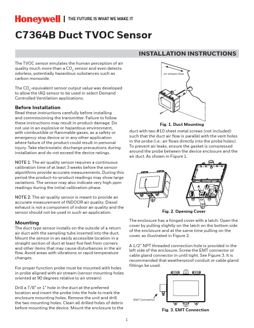
THE FUTURE IS WHAT WE MAKE ITC7364B Duct TVOC SensorINSTALLATION INSTRUCTIONSThe TVOC sensor emulates the human perception of air quality much more than a CO 2 sensor and even detects odorless, potentially hazardous substances such as carbon monoxide.The CO 2-equivalent sensor output value was developed to allow the IAQ sensor to be used in select Demand Controlled Ventilation applications.Before InstallationRead these instructions carefully before installing and commissioning the transmitter. Failure to follow these instructions may result in product damage. Do not use in an explosive or hazardous environment, with combustible or flammable gases, as a safety or emergency stop device or in any other application where failure of the product could result in personal injury. Take electrostatic discharge precautions during installation and do not exceed the device ratings.NOTE 1: The air quality sensor requires a continuous calibration time of at least 3 weeks before the sensor algorithms provide accurate measurements. During this period the product-to-product readings may show large variations. The sensor may also indicate very high ppm readings during the initial calibration phase.NOTE 2: The air quality sensor is meant to provide an accurate measurement of INDOOR air quality. Diesel exhaust is not a component of indoor air quality and the sensor should not be used in such an application.MountingThe duct type sensor installs on the outside of a return air duct with the sampling tube inserted into the duct. Mount the sensor in an easily accessible location in a straight section of duct at least five feet from corners and other items that may cause disturbances in the air flow. Avoid areas with vibrations or rapid temperature changes.For proper function probe must be mounted with holes in probe aligned with air stream (sensor mounting holes oriented at 90 degrees relative to air stream)Drill a 7/8” or 1” hole in the duct at the preferredlocation and insert the probe into the hole to mark the enclosure mounting holes. Remove the unit and drill the two mounting holes. Clean all drilled holes of debris before mounting the device. Mount the enclosure to theduct with two #10 sheet metal screws (not included)such that the duct air flow is parallel with the vent holes in the probe (i.e.: air flows directly into the probe holes). To prevent air leaks, ensure the gasket is compressed around the probe between the device enclosure and the air duct. As shown in Figure 1.The enclosure has a hinged cover with a latch. Open the cover by pulling slightly on the latch on the bottom side of the enclosure and at the same time pulling on the cover, as illustrated in Figure 2.A 1/2” NPT threaded connection hole is provided in the left side of the enclosure. Screw the EMT connector or cable gland connector in until tight. See Figure 3. It is recommended that weatherproof conduit or cable gland fittings be used.Fig. 3. EMT ConnectionThis device has a half-wave type power supply so the power supply common is the same as the output signal common. Therefore, several devices may be connected to one power supply and the output signals all share the same signal common. Use caution when grounding the secondary of an AC transformer or when wiring multiple devices to ensure that the circuit ground point is the same on all devices and the controller.Ensure the controller Analog Input (AI) matches the TVOC voltage output signal type before power is applied. The voltage signals have a minimum loadrating. Follow the ratings in the Specification section or inaccurate readings may result.Connect the LINEAR output signal to a 0-5 or 0-10 Vdc analog input port on the controller as shown in Figure 6. The device is factory configured for 0-5 Vdc output signal but may be changed to 0-10 Vdc via the menu. Changing output signal may be done during set up of the device. This linear output signal represents to 0-2000 ppm CO 2-equivalent value.The ASO (Analog Stepped Output) output signal is a second voltage signal that represents the three air quality levels of GOOD, FAIR, and POOR. Each level may be set independently via the menu to any value between 0 and 10 Vdc. The factory default is GOOD = 2.5 V, FAIR = 5.0 V, and POOR = 7.5 V. This signal canDUCT TVOC SENSORWiring•Deactivate the 24 Vac/dc power supply until all connections are made to the device to prevent electrical shock or equipment damage. Follow proper electrostatic discharge (ESD) handlingprocedures when installing the device or equipment damage may occur•Use 18-22 AWG shielded wiring for all connections and do not locate the device wires in the same conduit with wiring used to supply inductive loads such as motors. Make all connections in accordance with national and local codes.• Connector layout is shown in Figure 5. Diagram shown includes all options. If option is not ordered, connector will not be present.•Connect the positive DC voltage or the hot side of the AC voltage to the terminal marked POWER. The power supply common is connected to the terminal marked COMMON as shown in Figure 6.•The device is reverse voltage protected and will not operate if connected backwards.Fig. 4. Secure CoverFig. 5. PCB LayoutPOWER LINEARCOM PWR ASO LINEARN.O.RELAYUP DOWN MENUTwo security screws are provided which can be installed to help secure the cover once settings and wiringconnections are complete. See Figure 4.Fig. 6. WiringDUCT TVOC SENSORalso be connected to a controller analog input, or it can be connected directly to a 0-5 or 0-10 Vdc input of a damper actuator for direct ventilation control as shown in Figure 7. In this way, the Indoor Air Quality Sensor can be used as a stand-alone device. Since all steps are completely adjustable, the device can also drive a reverse acting actuator.The relay output available on the RELAY terminals. The relay output terminals are completely isolated from other connections and are NOT connected to the signal COMMON terminal as shown in Figure 8. This signal can be used to directly control an alarm, a ventilation fan or may be connected to a digital input of a Building Automation System for status monitoring. Respect the relay contact specification as listed in this document.Set-UpVerify that the TVOC sensor is properly wired and all connections are tight. Apply power to the device and note that the LCD will display the software versionnumber for a few seconds and then the device will enter Warm Up mode. The Warm Up mode will last for five minutes and the LCD will count down the time. This time is required to allow the device and sensor to reach normal operating temperature. After the five minutes has expired the device will enter normal operation and the LCD will indicate the TVOC status and ppm value.OperationIn normal operation, the TVOC sensor will detect a broad range of reducing gases such as CO and VOCs and translate the measurement into a parts per million (ppm) CO 2 equivalent value. This value is displayed on the LCD in either ppm or % as set in the menu. The air quality value is also displayed as either GOOD, FAIR or POOR and these values can also be set via the menu.The GOOD, FAIR and POOR air quality levels control the Analog Stepped Output (ASO) signal. The ASO output signal comprises of three independently set voltage levels that can be used to directly control a damper actuator for three positions. The levels are set via the menu and each level can be set anywhere from 0-10 Vdc. The GOOD, FAIR and POOR air quality levels will also be displayed on the tri-color front panel LED. The LED colors are displayed as GOOD = green, FAIR = blue and POOR = red. If required, the LED operation can be disabled via the menu.The air quality value is also sent to the LINEAR output as a 0-5 or 0-10 Vdc signal to represent the 0-2000 ppm CO 2 equivalent. This signal can interface to any voltage analog input for logging or control purposes.The linear output scaling and ASO operation is shown below. Note that the ASO GOOD/FAIR trip level = 1000 ppm and the FAIR/POOR trip level = 1500 ppm. The ASO output levels are GOOD = 2.5 V, FAIR = 5.0 V and POOR = 7.5 V.The normally open relay will close when the airquality exceeds a pre-set trip point. The trip point and hysteresis value can be programmed via the menu such that the relay closes when IAQ > Relay Setpoint and opens when IAQ < Relay Setpoint - Hysteresis. By default, the relay has a one minute minimum onand off time to prevent short cycling. This feature may be disabled via the menu. The menu may alsobe used to test the relay function. The relay can be used to control an alarm, fan directly or to signal a digital input.Fig. 7. ASO WiringFig. 8. Relay WiringASODUCT TVOC SENSOROther features and configuration are described in the Setup Menu section.NOTE: The air quality sensor requires a continuous burn-time of at least 3 weeks before the sensoralgorithms provide accurate measurements. During this period the product-to-product readings may show large variations. The sensor may also indicate very high PPM readings during the initial burn-in phase.The TVOC sensor is meant to provide an accurate measurements of INDOOR air quality. Diesel exhaust is not a component of indoor air quality and the sensor should not be used in such an application.MenuThe menu may be accessed any time after the initial warm-up period. The menu is controlled by using the three buttons on the PCB labeled UP, DOWN, and MENU. All values entered are saved in non-volatilememory and will be restored correctly in case of a power failure.The menu has several items as shown below. To enter the menu, press and release the <MENU> key while in normal operation. This will enter the User menu step 1, pressing the <MENU> key a second time advances to step 2. Each press of the <MENU> key advances the menu item. The <UP> and <DOWN> keys are used to make changes to program variables by scrollingthrough the available options. When a value is changed, use the <MENU> key to save it to memory and advance to the next menu item. Actual menu displays with the factory default value are shown.NOTE: If no keys are pressed for 2 minutes, the menu will automatically exit.IAQ Unit ppmThe LCD displays the IAQ sensor reading from 450-2000 ppm. Use<UP> or <DOWN> to change from ppm (default) to % for 0-100 % display. 0-100% = 450-2000 ppm. Thissetting has no effect on the LINEAR output signal, it is always scaled 0-2000 ppm = 0-5/0-10 Vdc.<MENU>Press to advance to next menu item1. IAQ UnitIAQ G/F 1000 ppmThis sets the trip point from Good to Fair IAQ for the LED and ASO. Thefactory default is 1000 ppm. Use <UP> or <DOWN> to change from 700 to 1200 ppm in 25 ppm steps.<MENU>Press to advance to next menu item2. IAQ G/F IAQ F/P 1500 ppmThis sets the trip point from Fair to Poor IAQ for the LED and ASO. The factory default is 1500 ppm. Use <UP> or <DOWN> to change from 1300 to 1700 ppm in 25 ppm steps. Note that both IAQ trip points have a 25 ppm hysteresis built in.<MENU>Press to advance to next menu item3. IAQ F/P Analog Out 5VThe LINEAR analog output signaldefaults to 0-5 Vdc. It can be changed with <UP> or <DOWN> to 0-10 Vdc. The selected scale is always equal to 0-2000 ppm.<MENU>Press to advance to next menu item4. Analog Output ASO Good 2.5 VdcThis sets the ASO output voltage for the Good range. It can be set using <UP> or <DOWN> anywhere from 0-10 Vdc. Resolution is 0.1 Vdc. The ASO output changes accordingly.<MENU>Press to advance to next menu item5. ASO Good Output ASO Fair 5 VdcThis sets the ASO output voltage for the Fair range. It can be set using <UP> or <DOWN> anywhere from 0-10 Vdc. Resolution is 0.1 Vdc and ASO out updates.<MENU>Press to advance to next menu item6. ASO Fair Output ASO Poor7.5 VdcThis sets the ASO output voltage for the Poor range. It can be set using <UP> or <DOWN> anywhere from 0-10 Vdc. Resolution is 0.1 Vdc and ASO out updates.<MENU>Press to advance to next menu item7. ASO Poor Output IAQ Cal 0 ppmUse <UP> or <DOWN> to add orsubtract an offset to the IAQ signal. This can change from -200 to + 200 ppm in 10 ppm increments.<MENU>Press to advance to next menu item8. IAQ CalibrationRelay Test OFFRelay SP 1000 PPMUse <UP> or <DOWN> to toggle the relay on or off for testing.Use <UP> or <DOWN> to change the relay setpoint from 750-1500 ppm. Default is 1000. Resolution is 25 ppm.<MENU>Press to advance to next menu item<MENU>Press to advance to next menu item9. Relay Test 10. Relay Set Point Relay Hy 100 PPMRelay Dly YESRelay Op NOCan change the relay hysteresis to 20, 50, 100, or 200 ppm. Default is 100.By default, the relay has a 1 minute minimum on time and a 1 minute minimum off time to prevent fast cycling. This feature can be disabled here.By default, the relay is normallyopen as its non-energized state. Use <UP> or <DOWN> to change to NC (normally closed).<MENU>Press to advance to next menu item<MENU>Press to advance to next menu item<MENU> Exits the User menu and returns the normal operation. The LCD flashes“Menu Exits” for 3 seconds.11. Relay Hysteresis 12. Relay Delay 13. Relay Open/ClosedDimensionsTHE FUTUREIS WHAT WE MAKE IT® U.S. Registered Trademark © 2020 Honeywell International Inc.Printed in Canada 31-00414-01WEEE Directive 2012/19/EC Waste Electrical and Electronic Equipment directiveAt the end of the product life dispose of the packaging and product in a corresponding recycling centre. Do not dispose of the unit with the usual domestic refuse. Do not burn the product.Honeywell Building TechnologiesIn the U.S.:Honeywell715 Peachtree Street NE Atlanta, GA WARNING: This product can expose you to chemicals which are known to the State of California to cause cancer/birth defects or other reproductive harm. For more information go to .。
苹果笔记本点位图查看手册
苹果笔记本点位图查看手册以M98为例。
苹果笔记本点位图查看软件为:T_link01(new) 一、打开界面。
二、操作快捷方法。
其中:+ (双击左键)放大- (单击右键)缩小HOME (单击中键)返回原始大小。
查询关键点(单击左键)ON(这个看不清) ↑上移图↓下移图←左移图→右移图V 显示所有点的名称(再按一下可以取消)R 旋转图像。
O 查找测试点。
(也可能是过孔吧,我没有板不好测试)S 查找与某一测试点相连的引脚、元件。
N 查找信号。
C 查找元件。
SPACE 正、反面转换其他两个就不用多说了吧。
三、实例操作。
缩放和移动、旋转就不说了,地球人应该都知道。
1、V——显示所有点名称。
2、O——查找测试点。
查找22和4测试点。
一次可以查三个点,分别以不同的颜色显示。
3、S——查找与某一测试点相连的引脚、元件查找与4相连的引脚。
这个也可以一次查3个。
4、N——查找信号以查找PP5V_S0为例。
5、C——查找元件以查找Q7930为例四、提高部分以上只是介绍了一下如何单独使用各功能。
做为维修人士,应该综合以上各功能,熟练应用。
下面以一简单例子作一引子。
希望对大家有用。
我们通过查M98的AC输入为例:1、查保险F6905通过点F6905第二引脚,得到如下信息:这个元件是:F6905,引脚信号:PPDCIN_G3H,测试点为:1707.通过中图纸查PPDCIN_G3H,得到如下信息:2、通过用S查1707,可能得到与F6905第2脚相连的引脚,得出AC电流的流向。
一路与Q7060的S极相连。
通过查Q7060的G 极,得到PPDCIN_G3H信号的控制信号:CHGR_AGATE_DIV。
3、通过N查CHGR_AGATE_DIV信号,得到CHGR_AGATE_DIV的测试点:14474、通过用S查1447,可能得到与CHGR_AGATE_DIV相连的引脚,得出AC电流的控制元件。
当然,这些也能从图纸上得到。
以上只是一个小的例子。
ipodtouch说明书
Ipod touch 使用说明及心得安装、同步、操作1、从/download下载并安装最新版本的itunes2、通过附带线缆将iPod连接至MAC(苹果电脑)或者个人电脑的USB接口。
3、根据屏幕提示设置ipod。
让它和你的音乐、视频、图片等同步。
你可以从itunes资料库(itunes store)下载音乐、视频以及其他内容,你也可以从光盘导入音乐。
更多资讯,你可以:查看iPod touch使用演示/ipodtouch/guidedtour要通过iPod touch查看用户手册,你可以在iPod touch的网络浏览器Safari 里输入/ipodtouch,如果你需要全部的使用介绍和重要的安全信息,可以通过下面的网址查看/support/manuals/ipod请注意*连接因特网必须要有Wi-Fi的支持;可能需要交纳费用。
2008苹果有限公司。
保留所有解释权。
苹果公司于加利福尼亚州设计,于中国印刷。
Z034-4675-A主菜单于任何时候点击主菜单键,都将回到iPod touch的主界面;你在任何目录里面操作的时候,只要双击主菜单键,屏幕都将回到iPod touch的设置界面。
当你在欣赏音乐的时候,你可以运行其他程序或者通过Wi-Fi*冲浪于网络。
按住开/关键可以进行开/关机。
歌曲和视频操作点击“专辑”或“视频”将打开相应的操作菜单,再次点击可以隐藏它们。
点击音乐列表上的其他按钮可以查看该专辑的其他歌曲。
双击正在播放的视频可以在竖屏和宽屏之间切换。
Retate (旋转)iPod touch to flick through your album art in Cover Flow.从苹果资料库(App Store)添加其他应用程序在苹果资料库里面,你可以找到各种类别的应用程序——游戏、社会(社交)网络应用软件、体育、旅行方面等等,其中有的还是免费的(也就是说,有的你还得掏钱才能下载)。
选择你需要的应用程序,并下载到你的iPod touch,你就可以马上运行它们,前提也是你需要一个Wi-Fi网络的支持。
苹果电脑使用技巧手册
苹果电脑使用技巧手册教你玩转apple:一、开机时按下滑鼠按键弹出抽取式媒介(2.4f1版以前的BootROM可能不包括退出CD片) opt键在配备「NewWorld」韧体系统的机种上叫出「OpenFirmware」开机系统选择功能。
cmd-opt键按住这两个键,直到电脑发出二次声响,就会改以MacOS9开机。
cmd-x (有时只按住x键)如果MacOS9和MacOSX在同一个开机用的硬碟区段(partition)上,按这个键会强迫以OSX开机。
cmd-opt-shift-delete跳过原定的启动磁碟,改以外接磁碟(或光碟机)开机。
这个按键的主要作用,其实是强迫电脑不要从预设的启动磁碟读入系统档案,所以会产生从其他磁碟开机的「副作用」。
如果您的Mac是配备SCSI介面的机种,它会从编号(ID)最高的磁碟机往下搜寻,直到找出可以开机的磁碟区段为止。
至於在配备IDE介面的机种上则不确定它的搜寻顺序。
cmd-opt-shift-delete-#从指定ID的SCSI磁碟开机(#代表SCSI编号)。
cmd-opt-p-r清除系统参数记忆体(PRAM),必须按住不放,等发出两次响声之后再放开。
cmd-opt-n-v清除NVRAM,类似在OpenFirmware中做「重置全部」(reset-all)的动作。
cmd-opt-o-f开机时进入openfirmware。
cmd-opt-t-v强制QuadraAV机种使用外接电视机当作显示器。
cmd-opt-x-o以唯读记忆体中所烧录的系统软体开机(仅适用於MacClassic 机种)。
cmd-opt-a-v强制电脑辨识苹果AV显示器。
c使用光碟开机。
如果原先设定由OSX开机,但光碟机里没有放置开机光碟,则可能会改由OS9开机。
d 强制以内建磁碟机开机。
n按住n键直到萤幕上出现Mac标志,电脑会尝试透过BOOTP或TFTP以网路伺服器开机。
r强制PowerBook重置萤幕设定。
MacBook_Pro_13inch_Mid2010_CH说明书
/macbookpro
MacBook Pro
Mac OS X Snow Leopard
/macosx
iLife ’11
/ilife
目录
第 1 章: 准备、安装、使用
16 第 1 章 准备、安装、使用
要唤醒 MacBook Pro: m 如果显示屏是合上的,则只需打开它就可以唤醒 MacBook Pro。 m 如果显示屏已打开,请按下电源按钮 (®) 或键盘上的任意键。
将 MacBook Pro 从睡眠状态唤醒之后,应用程序、文稿和电脑设置将与您离开之前的状态保持 一致。
称。开启 MacBook Pro 后,“设置助理”会引导您完成连接过程。有关故障排除方面的技巧, 请参阅第 60 页。 Â 要使用有线连接,请将以太网电缆的一端连接到 MacBook Pro,然后将另一端连接到线缆调制 解调器、DSL 调制解调器或网络。
G
第 1 章 准备、安装、使用 11
®
®
步骤 3: 快速按下电源按钮 (®) 以开启 MacBook Pro。 开机时您会听到电脑的启动声音。
9 包装箱中的物品 9 安装 MacBook Pro 16 将 MacBook Pro 置入睡眠状态或将它关机
第 2 章: 体验 MacBook Pro 生活
20 MacBook Pro 的基本功能 22 MacBook Pro 的键盘功能 24 MacBook Pro 上的端口 26 使用 Multi-Touch 触控板 30 使用 MacBook Pro 电池 31 故障排除
将 MacBook Pro 关机
如果您在两天或更长时间内都不会使用 MacBook Pro,最好将它关机。在关机过程中,睡眠指示 灯会短暂地亮起。 要将 MacBook Pro 关机,请执行以下一项操作: m 从菜单栏中选取苹果菜单 () >“关机”。 m 按下电源按钮 (®) 并在出现的对话框中点按“关机”。 如果您打算长期存放 MacBook Pro,请参阅第 73 页以了解有关如何防止电池完全耗尽的信息。
- 1、下载文档前请自行甄别文档内容的完整性,平台不提供额外的编辑、内容补充、找答案等附加服务。
- 2、"仅部分预览"的文档,不可在线预览部分如存在完整性等问题,可反馈申请退款(可完整预览的文档不适用该条件!)。
- 3、如文档侵犯您的权益,请联系客服反馈,我们会尽快为您处理(人工客服工作时间:9:00-18:30)。
教你玩转apple:一、开机时按下滑鼠按键弹出抽取式媒介(2.4f1版以前的BootROM可能不包括退出CD片)opt键在配备「NewWorld」韧体系统的机种上叫出「OpenFirmware」开机系统选择功能。
cmd-opt键按住这两个键,直到电脑发出二次声响,就会改以MacOS9开机。
cmd-x(有时只按住x键)如果MacOS9和MacOSX在同一个开机用的硬碟区段(partition)上,按这个键会强迫以OSX开机。
cmd-opt-shift-delete跳过原定的启动磁碟,改以外接磁碟(或光碟机)开机。
这个按键的主要作用,其实是强迫电脑不要从预设的启动磁碟读入系统档案,所以会产生从其他磁碟开机的「副作用」。
如果您的Mac是配备SCSI介面的机种,它会从编号(ID)最高的磁碟机往下搜寻,直到找出可以开机的磁碟区段为止。
至於在配备IDE介面的机种上则不确定它的搜寻顺序。
cmd-opt-shift-delete-#从指定ID的SCSI磁碟开机(#代表SCSI编号)。
cmd-opt-p-r清除系统参数记忆体(PRAM),必须按住不放,等发出两次响声之後再放开。
cmd-opt-n-v清除NVRAM,类似在OpenFirmware中做「重置全部」(reset-all)的动作。
cmd-opt-o-f开机时进入openfirmware。
cmd-opt-t-v强制QuadraAV机种使用外接电视机当作显示器。
cmd-opt-x-o以唯读记忆体中所烧录的系统软体开机(仅适用於MacClassic机种)。
cmd-opt-a-v强制电脑辨识苹果AV显示器。
c使用光碟开机。
如果原先设定由OSX开机,但光碟机里没有放置开机光碟,则可能会改由OS9开机。
d强制以内建磁碟机开机。
n按住n键直到萤幕上出现Mac标志,电脑会尝试透过BOOTP或TFTP以网路伺服器开机。
r强制PowerBook重置萤幕设定。
t强制配备FireWire介面的机种进入外接磁碟模式(FireWireTargetDiskmode)。
shift关闭所有延伸功能(OS9或OSX之下的Classic环境)。
shift关闭登入项目,同时也会关闭所有不必要的程式核心(kernel)延伸功能(也就是所谓安全开机模式,仅适用OSX10.1.3或更新的系统版本)。
cmd开机时关闭虚拟记忆体(VirtualMemory,仅适用OS9或OSX之下的Classic环境)。
空白键开机时启动延伸功能管理程式(OS9或OSX之下的Classic环境)。
cmd-v开机过程中显示控制台讯息(仅适用OSX)。
cmd-s开机後进入单一使用者模式(仅适用OSX)。
cmd-opt-c-i先将系统时钟设定为日期1989年9月20日,然後以这个按键组合开机,就可以看到萤幕上显示特殊的系统小秘密(仅适用於MacIIci机种)。
cmd-opt-f-x先将系统时钟设定为日期1990年3月19日,然後以这个按键组合开机,就可以看到萤幕上显示特殊的系统小秘密(仅适用於MacIIfx机种)。
二、萤幕上出现小Mac笑脸时按下空白键开机时启动延伸功能管理程式(OS9或OSX之下的Classic环境)。
shift关闭包括MacsBug(一种程式设计师工具程式)在内的所有延伸功能(OS9或OSX之下的Clas_sic 环境)。
shift-opt关闭除了MacsBug之外的所有延伸功能(OS9或OSX之下的Classic环境)。
ctrl中断开机过程,进入MacsBug除错模式。
三、系统画面出现後按下??cmd-opt当OS9或OSX中的Classic环境连接磁碟机时,可以重建磁碟机的桌面档案。
opt不要开启任何系统视窗(MacOS9)。
shift在系统档案(Finder)启动时暂时不要开启系统视窗。
这些视窗并没有被真的关闭,只要您重新开机,这些视窗都就会照常出现(MacOSX)。
shift不要执行任何「启动项目」软体(MacOS9)。
四、在系统画面中按下按住opt键,再以滑鼠游标按视窗上的关闭方块关闭所有的系统视窗(除了弹出式视窗之外);按cmd-opt-w键也可以获得一样的效果。
cmdshift-opt-w关闭所有的系统视窗(包括弹出式视窗)。
cmd-右箭头键在档案视窗以列表模式显示时,开启一个档案夹。
cmd-opt-右箭头键在档案视窗以列表模式显示时,重复开启档案夹、以及其下所包含的多层档案夹。
cmd-左箭头键在档案视窗以列表模式显示时,关闭一个档案夹。
cmd-opt-左箭头键在档案视窗以列表模式显示时,重复关闭档案夹、以及其下所包含的多层档案夹。
cmd-上箭头键开启上一层档案夹。
在MacOSX中,如果事先并未选定档案夹、而且没有开启任何视窗,这个按键会开启现在使用者的专属目录。
cmd-opt-上箭头键开启上一层档案夹,并关闭现用档案夹。
cmd-opt-shift-上箭头键将桌面变成现用视窗,并且选择最上层磁碟机。
cmd-下箭头键开启选取的项目。
在MacOSX中,如果事先并未选定档案夹、而且没有开启任何视窗,这个按键会开启桌面档案夹。
cmd-opt-下箭头键开启选取的项目,并关闭现用的档案夹。
opt-滑鼠按键按条列档案视窗中的小三角形图像时,可以显示或隐藏下层档案夹中的内容。
tab键选择名称以下一个英文字母开头的档案夹。
shift-tab键选择名称以上一个英文字母开头的档案夹。
cmd-delete把选取的项目搬进XX桶五、在系统画面中的「视窗」选单中cmd-选取项目关闭视窗。
cmd-shift-选取项目将弹出式视窗归位。
cmd-opt-选取项目展开选取的视窗,并关闭其他所有视窗。
ctrl-选取项目展开选取的视窗,并隐藏其他视窗的内容。
ctrl-opt-选取项目启动选取视窗,并展开所有的其他视窗。
六、系统启动完毕之後在有电源按钮的机种上电源按钮在萤幕上显示包括「关机」、「睡眠」、以及「重新开机」按钮的对话框(请参阅下一节)。
cmd-ctrl-电源按钮强制重新开机。
这种方式非必要不建议使用,因为有可能损坏磁碟上的资料内容。
ctrl-cmd-opt-电源按钮快速关机。
cmd-电源按钮启动程式除错软体(如果已事先安装的话)。
较早期的Mac(例如MacII时代的机器)需要先安装由PaulMercer所写的除错延伸功能(debuggerinit)来使用这个功能;不过这个功能在配备68040处理器的Mac机种上,已经成为系统韧体内容的一部份。
cmd-opt-电源按钮让後期型式的PowerBook和桌上型Mac进入睡眠状态。
cmd-opt-ctrl-电源按钮重新设定电源管理程式(PowerManager;仅适用PowerBook500系列)。
shift-fn-ctrl-电源按钮重新设定电源管理程式(PowerManager;仅适用PowerBookG3与G4系列)。
七、在没有电源按钮的机种上ctrl-退片按钮「退片」按钮位於新款USB键盘的最右上角,平常用於退出光碟片。
按下这个组合可以在萤幕上显示包括「关机」、「睡眠」、以及「重新开机」按钮的对话框(请参阅下一节)。
cmd-ctrl-退片按钮强制重新开机,正常状况下不建议使用。
ctrl-cmd-opt-退片按钮快速关机。
cmd-退片按钮启动程式除错软体(如果已事先安装的话)。
较早期的Mac(例如MacII时代的机器)需要先安装由PaulMercer所写的除错延伸功能(debuggerinit)来使用这个功能;不过这个功能在配备68040处理器的Mac机种上,已经成为系统韧体内容的一部份。
cmd-opt-退片按钮让後期型式的PowerBook和桌上型Mac进入睡眠状态。
八、在所有机种上cmd-opt-esc强迫退出目前使用中的软体。
cmd-shift-0让後期型式的PowerBook与桌上型Mac进入睡眠状态,不过在OSX上不适用。
如果在可以配备三部软碟机的Mac机种上(如MacSE),这个按键可以退出第三部软碟机中的碟片。
cmd-shift-1或2弹出内藏或外接软碟机中的碟片。
在可以配备两部软碟机的Mac(如MacSE或MacII)上,则是依次退出两部软碟机种的碟片。
cmd-shift-3拍摄萤幕图片cmd-shift-4拍摄使用者定义的萤幕区域。
在MacOS9中,如果在选定区域时按下Control键,则拍摄的内容会被储存在记忆体中的剪贴板里,可以直接在其他软体中「贴」上文件。
cmd-shift-大写固定键-4如果按下大写固定键(也就是「capslock」键),则可以拍摄使用者选定的视窗内容(仅适用於MacOS9或OSX下的Classic环境)。
cmd-ctrl-shift-3将萤幕图片拍摄至记忆体剪贴板。
cmd-ctrl-shift-4将使用者指定的萤幕区域拍摄至记忆体剪贴板。
cmd-ctrl-shift-大写固定键-4将使用者指定的视窗内容拍摄至记忆体剪贴板(仅适用於MacOS9或OSX下的Classic环境)。
cmd-tab切换执行中应用软体。
cmd-space切换使用的语言系统(如果已安装一种以上的语言系统)。
opt-F3、opt-F4、或是opt-F5开启MacOSX的「系统预置」视窗(仅在「系统预置」尚未执行的时候才有作用)。
cmd-F1在MacOSX中侦测显示器。
cmd-F2在MacOSX中切换萤幕同步显示内容。
F12退出CD或DVD(在(在MacOSX10.1.2或以上的版本中须按住不放)。
如果光碟可以被退出,按这个键就会退出。
如果不能退出(例如正在使用中),则按键没有作用。
F14让萤幕变暗(适用於G4Cube、iMacG4、或许还有其他机种)。
F15让萤幕变亮(适用於G4Cube、iMacG4、或许还有其他机种)。
cmd-ctrl-shift-0在执行MacOS9的PowerBook上,强制硬碟停止转动。
opt-「清除XX」选单指令不显示「有档案已经锁住」警示,直接清除XX桶内容;锁住的项目也会被删除。
九、在睡眠/重新开机对话框S键睡眠R键重新开机esc键取消cmd-.(英文句号)取消Return或Enter键关机电源按钮取消(可能仅适用於MacOS9.2.x)十、在其他对话框中esc键取消cmd-.(英文句号)取消Enter键预设按钮Return键预设按钮(如果同时没有其他文字栏位会用到return键)cmd-d不储存(在储存/□取消/□不储存对话框中)十一、在有「fn」键的键盘上fn-backspace往前删除字元十二、滑鼠按钮option-以滑鼠游标按另一个应用软体的视窗切换到另一软体,并隐藏现用软体。
cmd-拖移视窗拖移视窗,但不将该视窗切换至最前方(该应用软体必须支援视窗在对话框之後运作的功能)。