Agilent N9320B频谱仪实验指导
物理实验中如何正确使用频谱分析仪

物理实验中如何正确使用频谱分析仪在物理实验中,频谱分析仪是一种非常常见的仪器,它可以帮助科学家们分析信号的频谱成分,从而得到更加准确的实验结果。
然而,频谱分析仪的正确使用却并不是一件简单的事情,本文将介绍如何正确使用频谱分析仪,从而提高实验的准确性和可靠性。
首先,正确的连接与校准是使用频谱分析仪的关键。
在连接方面,我们需要将待测信号通过适当的电缆与频谱分析仪相连。
一般而言,我们需要选择合适的阻抗匹配器,以确保信号能够完全传递到频谱分析仪中,而不会出现丢失或衰减。
此外,我们还需要选择合适的衰减器,以防止信号过大而导致频谱分析仪损坏。
连接完成后,我们需要进行校准,以保证仪器的准确性。
校准主要包括垂直和水平校准。
垂直校准用于调整仪器的灵敏度,确保信号显示准确。
水平校准则用于调整频谱分析仪的时间基准,以保证观察到的频谱图形准确反映待测信号的频谱特性。
其次,正确的参数设置对于实验结果的准确性也非常关键。
在设置参数时,我们需要根据待测信号的特点进行选择。
首先,我们需要选择适当的频谱范围,以保证所有重要的频率成分能够被观察到。
如果频谱范围过小,可能会导致信号的重要频率成分被忽略。
反之,如果频谱范围过大,可能会导致噪声信号的影响。
其次,我们需要选择适当的频率分辨率。
频率分辨率指的是仪器能够分辨的最小频率单位。
如果频率分辨率过高,会导致仪器的计算负荷过大,从而降低仪器的响应速度。
而如果频率分辨率过低,可能会无法精确分辨不同频率成分。
最后,我们还需要选择合适的时间窗口长度。
时间窗口长度指的是在频谱分析中取样的时间段长度。
选择合适的时间窗口长度可以保证对于不同频率成分的分析都能够得到准确的结果。
此外,在实验过程中,我们还需要注意信号干扰的问题。
首先,我们需要确保实验场所的电磁环境良好,以避免外界电磁辐射对实验结果的影响。
其次,我们还需要避免信号源产生的额外噪声。
一般而言,我们可以通过避免信号源与其他电磁设备相互干扰,控制信号源的输出幅度和频率稳定性,以及选用合适的滤波器等方法来降低噪声的影响。
Agilent频谱分析仪基本操作简介
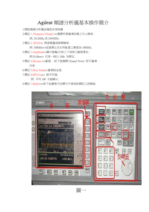
Agilent頻譜分析儀基本操作簡介
1.開啟頻譜分析儀並確認各項按鍵
2.標記1, Frequency Channel =>選擇所要量測信號之中心頻率.
例: 2412MHz.或2484MHz .
3.標記2, SPAN=> 將螢幕畫面展開頻率.
例: 100MHz=>從螢幕左至右所能看之頻寛為100MHz.
4.標記3.Amplitude=>顯示振幅,代表上下刻度之幅度單位.
例:10 dbm=> 代表一格以10db 為單位.
5.標記4.Measure =>量測 . 按下後選擇Channel Power 即可量測
功率.
6.標記5.Meas Setup=>量測設定值.
7.標記6.BW/Avg=> 做平均值.
例: 平均100 次做顯示.
8.標記7.Marker=>按下此鍵後可由標示中看到該標記之訊號值.
圖一
例如﹕需要量測2412Mhz的波形及POWER大小
0.先按下標記1位置並以數字鍵按21412後選MHz(如圖二紅框右方之按鍵). 即調整好頻
率.(圖二)
圖二
1.按下標記2即以數字鍵按100後按MHz(紅框右方按鍵) 即調整
好頻寛. (圖三)
圖三
12.按下標記3以數字鍵按20後選dBm位置按鈕. (圖四)
圖四13.按下標記4選擇Channel Power 以量測功率增益. (圖五)
圖五
14.Channel Power 後, 先選取Integ BW 按下20MHz (量測之頻寛20MHz),再選Chan Pwr
Span 選擇35MHz .(代表由蛍幕左方至右方僅35MHz 頻寛.
(圖六)
15.接上待測品後量取功率增益。
是德科技keysight n9320b射频频谱分析仪使用手册说明书技术指标,原安捷伦agilent
Keysight N9320BRF Spectrum Analyzer9 kHz to 3.0 GHzData SheetThe spectrum analyzer will meet itsspecifications when:It is within its calibration cycle It has been turned on at least 30 minutes. It has been stored at an ambient temperature within the allowed operating range for at least two hours before being turned on; if it has been stored previously at a temperaturerange inside the allowed storage range, but outside the allowed operating range.“Specifications” describe the performance of parameters covered by the productwarranty and apply to the full temperature range of 5 to 45 °C, unless otherwise noted.“Typical” values describe additional product performance information that is not covered by the product warranty. It is performance beyond specifications that 80 percent of the units exhibit with a 95 percent confidence level over the temperature range 20 to 30 °C. Typical performance does not include measurement uncertainty.“Nominal” values indicate expected performance, or describe product performance that is useful in the application of the product, but are not covered by the product warranty.Definitions and ConditionsRange1 Hz to 1 MHz in 1-3-10 sequence—3 dB bandwidth1. Frequency reference uncertainty = Aging rate x period since adjustment + supply voltage stability + temperature stability.Frequency and Time SpecificationCenter frequency 50 MHz, RBW 1 kHz, VBW 1 kHz, amplitude scale log, span 100 kHz, sweep time coupled, peak detector, signal at reference level Preamp off ± 0.3 dB Reference level —10 dB, input attenuation 10 dB Preamp on ± 0.4 dB Reference level —30 dB, input attenuation 10 dBAmplitude SpecificationsAmplitude Specifications (continued) Frequency range 1 MHz to 3.0 GHz Gain18 dB nominalDynamic Range SpecificationsPreamp off, signal input —30 dBm, 0 dB RF attenuationSecond harmonic distortion10 to 200 MHz+30 dBm200 to 500 MHz+35 dBm500 MHz to 3 GHz+43 dBmPreamp off, signal input -30 dBm, 0 dB RF attenuationThird-order intermodulation (TOI)300 MHz to 3 GHz+10 dBm; +13 dBm nominalTracking Generator Specifications (Option TG3 required)Average total power 30 dBm (1 W)AC coupled0 VDC MAXOffset from CW signal10 kHz < —88 dBc/Hz < —90 dBc/Hz Fc = 1 GHz, RBW = 1 kHz, VBW = 10 Hz, and sample detector, log average, average times > 40100 kHz < —100 dBc/Hz < —102 dBc/Hz 1 MHz< —110 dBc/Hz < —112 dBc/Hz Residual FM≤ 100 Hz peak-to-peak in 100 ms1 kHz RBW, 1 kHz VBWDynamic Range Specifications (continued)Modulation Analysis SpecificationsSymbol rate range 1 to 100 kHFSK deviation range 1 to 400 kHzAccuracy± 4% nominal b ≥1 and b ≤ 4, b is the ratio of frequencydeviation to symbol rateDisplayed resolution0.01 HzInputs and OutputsOutput amplitude> 0 dBmConnector and impedance BNC-type female, 50 Ω10 MHz reference input Input amplitude—5 to +10 dBmFrequency lock range± 5 ppm of specified external reference inputfrequencyConnector and impedance BNC-type female, 50 ΩExternal trigger input Input amplitude 5 V TTL levelConnector and impedance BNC-type female, 10 kΩVGA output VGA analog RGB31.5 kHz horizontal, 60 Hz vertical sync rates,non-interlacedD-sub 15-pin female connector VGA compatible640 x 480 screen resolutionLAN TCP/IP interface10Base, RJ-45 connectorUSB interface (device) B plug, version 1.1GPIB interface IEEE-488 bus connector Optional G01 installedGeneralThe recommended calibration cycle is one year. Calibration services are available through Keysight Service CentersRelated Literature–Keysight N9320B RF Spectrum Analyzer, Brochure, literature number 5990-8118EN–Keysight N9320B RF Spectrum Analyzer, Configuration Guide, literature number 5990-8120ENmyKeysightA personalized view into the information most relevant to you.AdvancedTCA® Extensions for Instrumentation and Test (AXIe) is anopen standard that extends the AdvancedTCA for general purpose and semiconductor test. Keysight is a founding member of the AXIe consortium. ATCA®, AdvancedTCA®, and the ATCA logo are registered US trademarks of the PCI Industrial Computer Manufacturers Group.LAN eXtensions for Instruments puts the power of Ethernet and theWeb inside your test systems. Keysight is a founding member of the LXI consortium.PCI eXtensions for Instrumentation (PXI) modular instrumentation delivers a rugged, PC-based high-performance measurement and automation system.Three-Year Warranty/find/ThreeYearWarrantyKeysight’s commitment to superior product quality and lower total costof ownership. The only test and measurement company with three-year warranty standard on all instruments, worldwide.Keysight Assurance Plans/find/AssurancePlansUp to five years of protection and no budgetary surprises to ensure your instruments are operating to specification so you can rely on accurate measurements./go/qualityKeysight Technologies, Inc.DEKRA Certified ISO 9001:2008Quality Management SystemKeysight Channel Partners/find/channelpartnersGet the best of both worlds: Keysight’s measurement expertise and product breadth, combined with channel partner convenience./find/n9320b For more information on Keysight Technologies’ products, applications or services, please contact your local Keysight office. The complete list is available at: /find/contactus AmericasCanada(877) 894 4414 Brazil55 11 3351 7010 Mexico001 800 254 2440 United States(800) 829 4444 Asia PacificAustralia 1 800 629 485 China800 810 0189 Hong Kong800 938 693 India 1 800 112 929 Japan0120 (421) 345 Korea080 769 0800 Malaysia 1 800 888 848 Singapore 1 800 375 8100 Taiwan0800 047 866 Other AP Countries(65) 6375 8100 Europe & Middle EastAustria0800 001122 Belgium0800 58580 Finland0800 523252 France0805 980333 Germany0800 6270999 Ireland1800 832700 Israel 1 809 343051 Italy800 599100 Luxembourg+32 800 58580 Netherlands0800 0233200 Russia8800 5009286 Spain800 000154 Sweden0200 882255 Switzerland0800 805353Opt. 1 (DE)Opt. 2 (FR)Opt. 3 (IT) United Kingdom0800 0260637 For other unlisted countries:/find/contactus(BP-09-23-14)11 | Keysight | M9037A PXIe Embedded Controller - Data SheetThis information is subject to change without notice.© Keysight Technologies, 2011 - 2014Published in USA, December 11, 20145990-8119EN。
频谱分析仪使用方法介绍

频谱分析仪使用方法介绍
5、测试前设置
频谱分析仪一般将参考电 平设置为-40dbm,分辨率 带宽(RBW)设置为 100KHz,输入衰减值设置 为0db。频谱分析仪支持 触屏,要修改的参数设置, 只需要触控相应参数,在 触控屏子菜单上选择相应 选项,用数字按键输入数 值,然后在触控屏子菜单 选择度量单位即可。
USB接口处
选择要拷贝的文件
点击COPY
选择拷贝目 标为USB
使用SELECT 可多选
毎扫完一个方向,均需要保存一张截图,并拍摄该方向上的现场照片,即毎完成一个测试点一个方向上的测试 至少要有两张频谱截图和一张现场照片。 频谱分析仪本身内存较大,可保存较多LOG,可每天测完后一次性拷贝,已拷贝出来的文件确定没问题后建议 从主机内存中删除,以免占用空间。
频谱分析仪使用方法介绍
频谱分析仪使用方法介绍
1、目前主流的频谱分析仪有泰克及安捷伦:
频谱分析仪使用方法介绍
2、设
由日本东北大学的八木秀次和宇田太郞两人发 明,被称为“八木宇田天线”,简称“八木天 线”,它有很好的方向性,较偶极天线有高的增 益,配上仰角和方位旋转,用它来测向、远距离 通信效果特别好
频谱分析仪使用方法介绍
6、扫频频段设置
频率设置
触控 屏子 菜单
单击触控主菜单“Freq” 在触控子菜单会显示 “Start Freq”和“Stop Freq”,分别点击选中, 用数字按键输入数值,然 后在触控屏子菜单选择度 量单位修改起止频率。对 不同频段进行频谱分析时 设置相应起始频率, 如 对GSM900 上行干扰频 谱分析时,设置“Start Freq”为880Mhz, “Stop Freq”为 915MHz 。
频谱分析仪使用方法介绍
频谱仪实验报告
频谱仪实验报告频谱仪实验报告引言频谱仪是一种用于测量和分析信号频谱的仪器。
它可以将复杂的信号分解成不同频率的成分,并以图形化的方式展示出来。
频谱仪在通信、无线电、音频等领域有着广泛的应用。
本实验旨在通过使用频谱仪,了解其原理和使用方法,并通过实际操作来验证其功能和精度。
实验目的1. 了解频谱仪的基本原理和工作方式;2. 掌握频谱仪的使用方法;3. 验证频谱仪的测量精度和稳定性。
实验器材和方法器材:频谱仪、信号发生器、电缆等;方法:根据实验步骤进行操作,记录实验数据并进行分析。
实验步骤1. 连接信号发生器和频谱仪:将信号发生器的输出端与频谱仪的输入端通过电缆连接起来。
2. 设置信号发生器:根据实验要求,设置信号发生器的频率、幅度等参数。
3. 打开频谱仪:按下频谱仪的开关,等待其启动。
4. 调整频谱仪参数:根据实验要求,调整频谱仪的参考电平、分辨率带宽等参数。
5. 观察频谱仪显示:通过频谱仪的显示屏,观察信号的频谱分布情况。
6. 记录实验数据:记录频谱仪显示的数据,包括频率、幅度等信息。
7. 分析实验结果:根据实验数据,分析信号的频谱特征和分布规律。
实验结果与分析在实验中,我们选择了一个简单的正弦信号作为输入信号,通过信号发生器将其输入到频谱仪中进行分析。
通过观察频谱仪的显示屏,我们可以清晰地看到信号的频谱分布情况。
实验数据显示,输入信号的频率为1kHz,幅度为2V。
频谱仪显示了信号的频谱特征,其中包括主频率分量和谐波分量。
主频率分量位于1kHz处,幅度为2V,而谐波分量则以倍频的形式出现在主频率的整数倍处。
通过对实验结果的分析,我们可以得出以下结论:1. 频谱仪能够准确地显示信号的频谱分布情况,包括主频率和谐波分量。
2. 频谱仪的测量精度较高,能够准确地测量信号的频率和幅度。
3. 频谱仪的稳定性较好,能够在长时间的实验过程中保持较高的测量精度。
实验总结通过本次实验,我们深入了解了频谱仪的原理和使用方法,并通过实际操作验证了其功能和精度。
Agilent N9320B RF Spectrum Analyzer 数据手册说明书
AgilentN9320B RF Spectrum Analyzer9 kHz to 3.0 GHzData Sheet1981Definitions and Conditions“Specifications” describe the performance of parameters covered by theproduct warranty and apply to the full temperature range of 5 to 45 °C, unlessotherwise noted.“Typical” values describe additional product performance information that isnot covered by the product warranty. It is performance beyond specificationsthat 80 percent of the units exhibit with a 95 percent confidence level over thetemperature range 20 to 30 °C. Typical performance does not include measure-ment uncertainty.“Nominal” values indicate expected performance, or describe product perfor-mance that is useful in the application of the product, but are not covered by theproduct warranty.2Frequency and Time Specification1. Frequency reference uncertainty = Aging rate x period since adjustment + supply voltage stability + temperature stability.3Amplitude Specifications4Amplitude Specifications (continued)56Dynamic Range Specifications7Tracking Generator Specifications(Option TG3 required)Dynamic Range Specifications (continued)Modulation Analysis Specifications8Inputs and Outputs9General10General (continued)Related Literature• Agilent N9320B RF Spectrum Analyzer, Brochure, literature number 5990-8118EN• Agilent N9320B RF Spectrum Analyzer, Configuration Guide, literature number 5990-8120EN11Agilent Email Updates/find/emailupdates Get the latest information on the products and applications you select.Agilent Channel Partners /find/channelpartners Get the best of both worlds: Agilent’s measurement expertise and product breadth, combined with channel partner convenience.For more information on AgilentTechnologies’ products, applications orservices, please contact your local Agilentoffice. The complete list is available at:/find/contactusAmericasCanada (877) 894 4414Brazil (11) 4197 3500Mexico 01800 5064 800United States (800) 829 4444Asia PacificAustralia 1 800 629 485China 800 810 0189Hong Kong 800 938 693India 1 800 112 929Japan 0120 (421) 345Korea 080 769 0800Malaysia 1 800 888 848Singapore 180****8100Taiwan 0800 047 866Other AP Countries (65) 375 8100Europe & Middle EastBelgium 32 (0) 2 404 93 40Denmark 45 70 13 15 15Finland 358 (0) 10 855 2100France 0825 010 700**0.125€/minuteGermany 49 (0) 7031 464 6333Ireland 1890 924 204Israel 972-3-9288-504/544Italy 39 02 92 60 8484Netherlands 31 (0) 20 547 2111Spain 34 (91) 631 3300Sweden 0200-88 22 55United Kingdom 44 (0) 131 452 0200For other unlisted countries:/find/contactusRevised: June 8, 2011Product specifications and descriptionsin this document subject to changewithout notice.© Agilent Technologies, Inc. 2011Published in USA, November 4, 20115990-8119EN/find/n9320bAgilent Advantage Services is committedto your success throughout your equip-ment’s lifetime. To keep you competitive,we continually invest in tools andprocesses that speed up calibration andrepair and reduce your cost of ownership.You can also use Infoline Web Servicesto manage equipment and services moreeffectively. By sharing our measurementand service expertise, we help you createthe products that change our world./quality/find/advantageservicesAgilent Education Corner/find/eduYour one-stop education resource for college and university engineering educators, researchers and studentsAgilent Product Registration /find/register Register your instruments for service notifications, firmware update alerts, application notes and more. You have the Agilent edge. Register today and keep it sharp。
SCPI程控指令学习实验指导书
STATus、SYSTem、TEST、TRACe|DATA、TRIGger、UNIT 和 VXI 等 23 个子系 统命令集。
利用 Agilent Connection Expert 根据仪器 IP 配置仪器后,主控机通过 LXI 总线发送 SCPI 命令控制仪器,并在用户界面上显示程控命令和结果。
自动设置视频带 宽 设置中心频率 根 据 Span 自 动 设置中心频率 设置中心频率步 进 设置频率 span 设置起始频率 设置终止频率 设 置 ACP 测 量 平均扫描次数 设 置 ACP 测 量 平均模式 设置计算主信道 功率的积分带宽 设置信道功率测 量平均扫描次数 设置信道功率测 量平均模式 设置计算信道功 率的积分带宽 CA 自动定标 LC 关闭所有的标记 ul 连续峰值搜索开 at 关
四. 实验原理
SCPI 的目标是缩短自动测试设备(ATE,Automatic Test Equipment)程序开 发时间。SCPI 通过为仪器控制和数据使用提供一致的编程环境来达成这一目标。 所有的 SCPI 仪器都使用定义好的程控消息、仪器响应和数据格式来实现兼容的 编程环境。
SCPI 提供几种不同层次的仪器控制,简单的测量命令为用户提供容易、快 速的 SCPI 仪器控制,与此同时,更详细的命令则可以用于提供传统仪器控制。
过冲测量 周期测量 上升时间测量 平均值测量 最大值测量 最小值测量 峰峰值测量 波 波形前缀 形 波形样点数 获 波形数据来源 取 波形数据格式 获取波形数据 状 管理状态报告 态 使能 管 读取状态报告 理 管理标准事件 寄存器 读取标准事件 寄存器 设置测量完成 状态报告
功能 系 识别 统 自检 功 复位 能 清除
实验一 可程控仪器标准代码(SCPI)学习
N9320B频谱仪说明书
• 直接使用一键式功率测量功能, 进行通道功率、ACP、OBW、 SEM 和 TOI 测量。
• N9320B 可为自动测试程序提供 业界标准的 SCPI 语言支持和连通性 选择(USB 和 LAN)。与 Agilent ESA-L 系列兼容的 SCPI 代码能够 轻松地从 ESA-L 过渡到 N9320B。
• 频率计数器能更精确地读取频率 • U 盘可快速保存和调用测量结果
6
教育
无论您是要指导研究生完成重 要的科研项目,还是通过实验培养 的本科生的动手能力。安捷伦测试 设备将保证您能以最高标准培养未 来的工程师。
掌握测试仪器的使用方法和了解 RF 信号之间的相互作用是学好电子类 课程的基础,频谱分析是 RF 电路设计 的基础。它能使学生清楚地看到信号 交互和混频的过程。
Kensington 安全锁
TTL 触发 信号输入
USB 接口 LAN 端口
可上架安装
3U 高度 易于适应您的测试柜
3
电子制造
您要更快和更高性价比的射频分析工具来测试今天的消费类电子产品和元件需 — 不要再犹豫了!
无论您是制造无线鼠标、键盘、 GPS 设备或 RF 元件,如混频器,滤 波器或放大器,您都需要测量它们的 射频特性,以保证在其设计参数范围 (如频带宽度和输出功率范围) 内正常工 作。过小的射频功率会降低无线工作 距离,而过高功率会很快耗尽电池的 能量,从而缩短工作时间,同时还会 造成设备过热。
Agilent N9320B RF 频谱分析仪
技术概览
9 kHz 至 3 GHz 专业的频谱分析性能 • 测量速度:
安捷伦 N9320B 频谱分析仪 说明书
安捷伦N9320B 频谱分析仪用户手册注意© Agilent Technologies, Inc. 2009根据美国和国际版权法,未经安捷伦科技事先同意和书面许可,本手册的任何部分不得以任何方式或手段(包括电子储存、检索或翻译为另一种语言)进行复制。
手册产品编号N9320-90006版本第一版,2008年12月中国印刷Agilent Technologies, Inc.中国 四川 成都高新西区前锋工业园,611731保证本文档所含资料均按原样提供,在以后的版本中如有修改,恕不另行通知。
此外,除非另有适用的法律允许,安捷伦对与此手册相关的内容及其中所含的信息不作任何明示或默许的保证,包括但不限于为特定目的的销售适用性所作的默许保证。
对由于文档中包含的信息或由供给、使用或执行本文档而引起的偶然或继发损失,安捷伦科技公司不承担任何责任。
如果在安捷伦和用户单独签订的书面协议中有关此文档资料的保证条款与此处的条款发生冲突,则以单独签订协议中的保证条款为准。
技术许可证本文档中所述的硬件和/或软件随附有许可证。
只能按照这些许可证中的条款规定使用或复制硬件和/或软件Restricted Rights LegendU.S. Government Restricted Rights. Soft-ware and technical data rights granted tothe federal government include only thoserights customarily provided to end user cus-tomers. Agilent provides this customarycommercial license in Software and techni-cal data pursuant to FAR 12.211 (TechnicalData) and 12.212 (Computer Software) and,for the Department of Defense, DFARS252.227-7015 (Technical Data - CommercialItems) and DFARS 227.7202-3 (Rights inCommercial Computer Software or Com-puter Software Documentation).安全提示小心小心表示存在危险。
N9320B频谱仪功能与应用简介
低於频谱仪的RBW,两信号将重叠,难以分辨,但较高的
RBW固然有助於宽频带信号的侦测,将增加底噪(Noise Floor),降低测量灵敏度,对於侦测低强度的信号易产生阻 碍,因此应综合考虑适当的RBW宽度。 >分辨率带宽><数字键>(softkey)
Page 20 ▶
N9320B频谱仪测量方法
设置VBW
Page 24 ▶
N9320B频谱仪测量方法
其他参数设置
触发控制设置
跟踪控制设置
回波损耗测试 以上功能需要配合跟踪发生器使用,在此不做说明。 如有兴趣了解,请参阅《N9320B User’s Guide》。
Page 25 ▶
N9320B频谱仪测量方法
添加标记
标记可以明确的显示出频谱图上的某点的频率和幅值。
Page 43 ▶
低电平信号测试
关闭频率计数器 >功能>频率计数器>频率计数器>(关) 使用频率计数器功能时,分辨率带宽与扫宽的比值必须大 于0.02。
Page 44 ▶
OVER
xx/mobile: …………………….
地址:武汉市光谷创业街67号 邮编:430073 邮箱:xwdeng@
频谱仪功能与工作原理
频谱仪功能 频谱仪的功能
频谱仪的主要功能是在频域里测量显示输入信号的频谱分布和 幅值信息,将复杂信号分离,或者解调为频率和幅值不同的正选
波。包括频率、功率、谐杂波、噪声、干扰失真等参数;如带有
调制解调功能的频谱仪,还能测量模拟电视信号的CSO、CTB、 C/N比等参数值。
注:目前公司的N9320B仪表不支持解调功能,无法测试CSO、CTB和
- 1、下载文档前请自行甄别文档内容的完整性,平台不提供额外的编辑、内容补充、找答案等附加服务。
- 2、"仅部分预览"的文档,不可在线预览部分如存在完整性等问题,可反馈申请退款(可完整预览的文档不适用该条件!)。
- 3、如文档侵犯您的权益,请联系客服反馈,我们会尽快为您处理(人工客服工作时间:9:00-18:30)。
Agilent N9320B频谱仪实验指导目录第一部分:按键说明 ..................................................................................................................- 1 - 幅度 (Amplitude) ..............................................................................................................- 1 - 自动调谐 (Auto Tune) ......................................................................................................- 1 - 后退 (Back<—) ..................................................................................................................- 2 - 带宽/平均(BW/Avg) ............................................................................................................- 2 - 检波 / 显示 (Det/Display) ............................................................................................- 4 - 确认 (Enter) ......................................................................................................................- 7 - 文件(File) ..........................................................................................................................- 7 - 频率 (Frequency) ........................................................................................................... - 11 - 标记 (Marker) ................................................................................................................. - 12 - 标记 ->(Marker->) ......................................................................................................... - 14 - 测量 (Meas) ..................................................................................................................... - 15 - 模式 (MODE) ..................................................................................................................... - 15 - 峰值搜索 (Peak Search) ............................................................................................... - 15 - 扫宽 (SPAN) ..................................................................................................................... - 21 - 扫描 / 触发 (Sweep/Trig) ........................................................................................... - 21 - 查看 / 轨迹 (View/Trace) ........................................................................................... - 22 - 第二部分:实验部分 ............................................................................................................... - 24 - 实验项目一:测量低电平信号........................................................................................ - 24 -一、试验项目名称:测量低电平信号.................................................................... - 24 -二、实验目的和任务:............................................................................................ - 24 -三、实验原理:........................................................................................................ - 24 -四、实验内容:........................................................................................................ - 24 -实验项目二:测量多个信号............................................................................................ - 28 -一、试验项目名称:测量多个信号........................................................................ - 28 -二、实验目的和任务................................................................................................ - 28 -三、实验原理:........................................................................................................ - 28 -四、实验内容:........................................................................................................ - 28 -实验项目三:识别由频谱仪产生的失真及测量相位噪声............................................ - 35 -一、实验项目名称:识别由频谱仪产生的失真及测量相位噪声........................ - 35 -二、实验目的和任务................................................................................................ - 35 -三、实验原理............................................................................................................ - 35 -四、实验内容............................................................................................................ - 35 -第一部分:按键说明这一章介绍了前端面板上的硬键和与其对应的软键。
软键的排列顺序与显示屏上的菜单顺序相同。
幅度 (Amplitude)按键激活参考电平功能,并进入以下幅度设置菜单。
参考电平(Rel Level):设置参考电平。
按键激活此项功能。
参考电平为屏幕顶端的栅格线所代表的功率或电压值(单位为所选的幅度单位)。
用户可以通过箭头键,旋钮或数值键盘改变参考电平值。
按键入口:衰减(Attenuation)自动(Auto)手动(Man):输入衰减可以在自动和手动之间切换。
选择自动时,按一次箭头键,输入衰减的数值变化5 dB。
分析仪的输入衰减器,在输入信号进入混频器之前降低其功率,通常与参考电平控制相结合。
当选择自动时,输入衰减值与参考电平联动。
用户可以通过箭头键,旋钮或数值键盘改变输入衰减值。
按键入口:刻度/格(Scale/Div):设置屏幕垂直方向上一个栅格对应的对数值。
刻度/格功能仅在刻度类型选择对数可用。
按键入口:刻度类型(Scale Type)对数(Log)线性(Lin):在刻度类型设为对数时,可以设置屏幕垂直方向上一个栅格对应的对数值。