土木外文翻译
土木工程专业外文翻译
DESIGN AND EXECUTION OF GROUND INVESTIGATION FOREARTHWORKSABSTRACTThe design and execution of ground investigation works for earthwork projects has become increasingly important as the availability of suitable disposal areas becomes limited and costs of importing engineering fill increase. An outline of ground investigation methods which can augment ‘traditional investigation methods’ particularly for glacial till / boulder clay soils is presented. The issue of ‘geotechnical certification’ is raised an d recommendations outlined on its merits for incorporation with ground investigations and earthworks.1. INTRODUCTIONThe investigation and re-use evaluation of many Irish boulder clay soils presents difficulties for both the geotechnical engineer and the road design engineer. These glacial till or boulder clay soils are mainly of low plasticity and have particle sizes ranging from clay to boulders. Most of our boulder clay soils contain varying proportions of sand, gravel, cobbles and boulders in a clay or silt matrix. The amount of fines governs their behaviour and the silt content makes it very weather susceptible.Moisture contents can be highly variable ranging from as low as 7% for the hard grey black Dublin boulder clay up to 20-25% for Midland, South-West and North-West light grey boulder clay deposits. The ability of boulder clay soils to take-in free water is well established and poor planning of earthworks often amplifies this.The fine soil constituents are generally sensitive to small increases in moisture content which often lead to loss in strength and render the soils unsuitable for re-use as engineering fill. Many of our boulder clay soils (especially those with intermediate type silts and fine sand matrix) have been rejected at the selection stage, but good planning shows that they can in fact fulfil specification requirements in terms of compaction and strength.The selection process should aim to maximise the use of locally available soils and with careful evaluation it is possible to use o r incorporate ‘poor ormarginal soils’ within fill areas and embankments. Fill material needs to be placed at a moisture content such that it is neither too wet to be stable and trafficable or too dry to be properly compacted.High moisture content / low strength boulder clay soils can be suitable for use as fill in low height embankments (i.e. 2 to 2.5m) but not suitable for trafficking by earthwork plant without using a geotextile separator and granular fill capping layer. Hence, it is vital that the earthworks contractor fully understands the handling properties of the soils, as for many projects this is effectively governed by the trafficability of earthmoving equipment.2. TRADITIONAL GROUND INVESTIGATION METHODSFor road projects, a principal aim of the ground investigation is to classify the suitability of the soils in accordance with Table 6.1 from Series 600 of the NRA Specification for Road Works (SRW), March 2000. The majority of current ground investigations for road works includes a combination of the following to give the required geotechnical data:▪Trial pits▪Cable percussion boreholes▪Dynamic probing▪Rotary core drilling▪In-situ testing (SPT, variable head permeability tests, geophysical etc.) ▪Laboratory testingThe importance of ‘phasing’ the fieldwork operations cannot be overstressed, particularly when assessing soil suitability from deep cut areas. Cable percussion boreholes are normally sunk to a desired depth or ‘refusal’ with disturbed and undisturbed samples recovered at 1.00m intervals or change of strata.In many instances, cable percussion boring is unable to penetrate through very stiff, hard boulder clay soils due to cobble, boulder obstructions. Sample disturbance in boreholes should be prevented and loss of fines is common, invariably this leads to inaccurate classification.Trial pits are considered more appropriate for recovering appropriate size samples and for observing the proportion of clasts to matrix and sizes of cobbles, boulders. Detailed and accurate field descriptions are therefore vitalfor cut areas and trial pits provide an opportunity to examine the soils on a larger scale than boreholes. Trial pits also provide an insight on trench stability and to observe water ingress and its effects.A suitably experienced geotechnical engineer or engineering geologist should supervise the trial pitting works and recovery of samples. The characteristics of the soils during trial pit excavation should be closely observed as this provides information on soil sensitivity, especially if water from granular zones migrates into the fine matrix material. Very often, the condition of soil on the sides of an excavation provides a more accurate assessment of its in-situ condition.3. ENGINEERING PERFORMANCE TESTING OF SOILSLaboratory testing is very much dictated by the proposed end-use for the soils. The engineering parameters set out in Table 6.1 pf the NRA SRW include a combination of the following:▪Moisture content▪Particle size grading▪Plastic Limit▪CBR▪Compaction (relating to optimum MC)▪Remoulded undrained shear strengthA number of key factors should be borne in mind when scheduling laboratory testing:▪Compaction / CBR / MCV tests are carried out on < 20mm size material.▪Moisture content values should relate to < 20mm size material to provide a valid comparison.▪Pore pressures are not taken into account during compaction and may vary considerably between laboratory and field.▪Preparation methods for soil testing must be clearly stipulated and agreed with the designated laboratory.Great care must be taken when determining moisture content of boulder clay soils. Ideally, the moisture content should be related to the particle size andhave a corresponding grading analysis for direct comparison, although this is not always practical.In the majority of cases, the MCV when used with compaction data is considered to offer the best method of establishing (and checking) the suitability characteristics of a boulder clay soil. MCV testing during trial pitting is strongly recommended as it provides a rapid assessment of the soil suitability directly after excavation. MCV calibration can then be carried out in the laboratory at various moisture content increments. Sample disturbance can occur during transportation to the laboratory and this can have a significant impact on the resultant MCV’s.IGSL has found large discrepancies when performing MCV’s in the field on low plasticity boulder clays with those carried out later in the laboratory (2 to 7 days). Many of the aforementioned low plasticity boulder clay soils exhibit time dependant behaviour with significantly different MCV’s recorded at a later date – increased values can be due to the drainage of the material following sampling, transportation and storage while dilatancy and migration of water from granular lenses can lead to deterioration and lower values.This type of information is important to both the designer and earthworks contractor as it provides an opportunity to understand the properties of the soils when tested as outlined above. It can also illustrate the advantages of pre-draining in some instances. With mixed soils, face excavation may be necessary to accelerate drainage works.CBR testing of boulder clay soils also needs careful consideration, mainly with the preparation method employed. Design engineers need to be aware of this, as it can have an order of magnitude difference in results. Static compaction of boulder clay soils is advised as compaction with the 2.5 or 4.5kg rammer often leads to high excess pore pressures being generated – hence very low CBR values can result. Also, curing of compacted boulder clay samples is important as this allows excess pore water pressures to dissipate.4. ENGINEERING CLASSIFICATION OF SOILSIn accordance with the NRA SRW, general cohesive fill is categorised in Table 6.1 as follows:▪2A Wet cohesive▪2B Dry cohesive▪2C Stony cohesive▪2D Silty cohesiveThe material properties required for acceptability are given and the design engineer then determines the upper and lower bound limits on the basis of the laboratory classification and engineering performance tests. Irish boulder clay soils are predominantly Class 2C.Clause 612 of the SRW sets out compaction methods. Two procedures are available:▪Method Compaction▪End-Product CompactionEnd product compaction is considered more practical, especially when good compaction control data becomes available during the early stages of an earthworks contract. A minimum Target Dry Density (TDD) is considered very useful for the contractor to work with as a means of checking compaction quality. Once the material has been approved and meets the acceptability limits, then in-situ density can be measured, preferably by nuclear gauge or sand replacement tests where the stone content is low.As placing and compaction of the fill progresses, the in-situ TDD can be checked and non-conforming areas quickly recognised and corrective action taken. This process requires the design engineer to review the field densities with the laboratory compaction plots and evaluate actual with ‘theoretical densities’.5. SUPPLEMENTARY GROUND INVESTIGATION METHODS FOR EARTHWORKSThe more traditional methods and procedures have been outlined in Section 2. The following are examples of methods which are believed to enhance ground investigation works for road projects:▪Phasing the ground investigation works, particularly the laboratory testing▪Excavation & sampling in deep trial pits▪Large diameter high quality rotary core drilling using air-mist or polymer gel techniques译文:土方工程的地基勘察与施工摘要:当工程场地的处理面积有限且填方工程费用大量增加时,土方工程的地基勘察设计与施工已逐渐地变得重要。
土木工程 外文文献翻译
学院:专业:土木工程姓名:学号:外文出处: Structural Systems to resist (用外文写)Lateral loads附件: 1.外文资料翻译译文;2.外文原文。
附件1:外文资料翻译译文抗侧向荷载的结构体系常用的结构体系若已测出荷载量达数千万磅重,那么在高层建筑设计中就没有多少可以进行极其复杂的构思余地了。
确实,较好的高层建筑普遍具有构思简单、表现明晰的特点。
这并不是说没有进行宏观构思的余地。
实际上,正是因为有了这种宏观的构思,新奇的高层建筑体系才得以发展,可能更重要的是:几年以前才出现的一些新概念在今天的技术中已经变得平常了。
如果忽略一些与建筑材料密切相关的概念不谈,高层建筑里最为常用的结构体系便可分为如下几类:1.抗弯矩框架。
2.支撑框架,包括偏心支撑框架。
3.剪力墙,包括钢板剪力墙。
4.筒中框架。
5.筒中筒结构。
6.核心交互结构。
7. 框格体系或束筒体系。
特别是由于最近趋向于更复杂的建筑形式,同时也需要增加刚度以抵抗几力和地震力,大多数高层建筑都具有由框架、支撑构架、剪力墙和相关体系相结合而构成的体系。
而且,就较高的建筑物而言,大多数都是由交互式构件组成三维陈列。
将这些构件结合起来的方法正是高层建筑设计方法的本质。
其结合方式需要在考虑环境、功能和费用后再发展,以便提供促使建筑发展达到新高度的有效结构。
这并不是说富于想象力的结构设计就能够创造出伟大建筑。
正相反,有许多例优美的建筑仅得到结构工程师适当的支持就被创造出来了,然而,如果没有天赋甚厚的建筑师的创造力的指导,那么,得以发展的就只能是好的结构,并非是伟大的建筑。
无论如何,要想创造出高层建筑真正非凡的设计,两者都需要最好的。
虽然在文献中通常可以见到有关这七种体系的全面性讨论,但是在这里还值得进一步讨论。
设计方法的本质贯穿于整个讨论。
设计方法的本质贯穿于整个讨论中。
抗弯矩框架抗弯矩框架也许是低,中高度的建筑中常用的体系,它具有线性水平构件和垂直构件在接头处基本刚接之特点。
土木建筑工程英汉词典

土木建筑工程英汉词典Soil Mechanics - 土力学Structural Analysis - 结构分析Concrete - 混凝土Steel - 钢铁Reinforcement - 钢筋Foundation - 基础Geotechnical Engineering - 岩土工程Shoring - 支护Excavation - 挖掘Tunneling - 隧道工程Surveying - 测量Geology - 地质学Hydraulics - 水力学Construction Management - 施工管理Structural Engineering - 结构工程Bridge - 桥梁Highway - 公路Irrigation - 灌溉Water Supply - 供水Foundation Design - 基础设计Soil Testing - 土壤测试Construction Materials - 建筑材料Earthquake Engineering - 地震工程Environmental Impact Assessment - 环境影响评价Safety Management - 安全管理Cost Estimation - 成本估算Project Planning - 项目规划Project Management - 项目管理Building Codes - 建筑规范Risk Assessment - 风险评估Contract Administration - 合同管理Quality Control - 质量控制Concrete Technology - 混凝土技术Steel Structures - 钢结构Engineering Drawing - 工程图纸Construction Equipment - 建筑设备Slope Stability - 边坡稳定性Dams - 水坝Seismic Design - 地震设计Construction Site - 建筑工地Structural Integrity - 结构完整性Water Treatment - 水处理Sustainable Construction - 可持续建筑Architectural Design - 建筑设计Material Testing - 材料测试Quantity Surveying - 工程测量Earthworks - 土方工程Structural Rehabilitation - 结构修复Road Construction - 道路建设Facade Design - 幕墙设计Construction Methodology - 施工方法论Retaining Wall - 挡土墙Heritage Conservation - 文物保护Building Maintenance - 建筑维护Engineering Ethics - 工程伦理Construction Waste Management - 建筑废弃物管理Public Infrastructure - 公共基础设施Landscape Architecture - 景观建筑。
土木工程专业英语词汇(整理版)
土木工程专业英语词汇(整理版)第一部分必须掌握,第二部分尽量掌握第一部分:1 Finite Element Method 有限单元法2 专业英语 Specialty English3 水利工程 Hydraulic Engineering4 土木工程 Civil Engineering5 地下工程 Underground Engineering6 岩土工程 Geotechnical Engineering7 道路工程 Road (Highway) Engineering8 桥梁工程Bridge Engineering9 隧道工程 Tunnel Engineering10 工程力学 Engineering Mechanics11 交通工程 Traffic Engineering12 港口工程 Port Engineering13 安全性 safety17木结构 timber structure18 砌体结构 masonry structure19 混凝土结构concrete structure20 钢结构 steelstructure21 钢 - 混凝土复合结构 steel and concrete composite structure22 素混凝土 plain concrete23 钢筋混凝土reinforced concrete24 钢筋 rebar25 预应力混凝土 pre-stressed concrete26 静定结构statically determinate structure27 超静定结构 statically indeterminate structure28 桁架结构 truss structure29 空间网架结构 spatial grid structure30 近海工程 offshore engineering31 静力学 statics32运动学kinematics33 动力学dynamics34 简支梁 simply supported beam35 固定支座 fixed bearing36弹性力学 elasticity37 塑性力学 plasticity38 弹塑性力学 elaso-plasticity39 断裂力学 fracture Mechanics40 土力学 soil mechanics41 水力学 hydraulics42 流体力学 fluid mechanics精品文库43 固体力学solid mechanics44 集中力 concentrated force45 压力 pressure46 静水压力 hydrostatic pressure47 均布压力 uniform pressure48 体力 body force49 重力 gravity50 线荷载 line load51 弯矩 bending moment52 扭矩 torque53 应力 stress54 应变 stain55 正应力 normal stress56 剪应力 shearing stress57 主应力 principal stress58 变形 deformation59 内力 internal force60 偏移量挠度 deflection61 沉降settlement62 屈曲失稳 buckle63 轴力 axial force64 允许应力 allowable stress65 疲劳分析 fatigue analysis66 梁 beam67 壳 shell68 板 plate69 桥 bridge70 桩 pile71 主动土压力 active earth pressure72 被动土压力 passive earth pressure73 承载力 load-bearing capacity74 水位 water Height75 位移 displacement76 结构力学 structural mechanics77 材料力学 material mechanics78 经纬仪 altometer79 水准仪level80 学科 discipline81 子学科 sub-discipline82 期刊 journal periodical83 文献literature84 国际标准刊号ISSN International Standard Serial Number精品文库85 国际标准书号ISBN International Standard Book Number86 卷 volume87 期 number88 专著 monograph89 会议论文集 Proceeding90 学位论文 thesis dissertation91 专利 patent92 档案档案室 archive93 国际学术会议 conference94 导师 advisor95 学位论文答辩 defense of thesis96 博士研究生 doctorate student97 研究生 postgraduate98 工程索引EI Engineering Index99 科学引文索引SCI Science Citation Index100 科学技术会议论文集索引ISTP Index to Science and Tec hnology Proceedings101 题目 title102 摘要 abstract103 全文 full-text104 参考文献 reference105 联络单位、所属单位affiliation106 主题词 Subject107 关键字 keyword108 美国土木工程师协会ASCE American Society of Civil Engineers109 联邦公路总署FHWA Federal Highway Administration110 国际标准组织ISO International Standard Organization111 解析方法 analytical method112 数值方法 numerical method113 计算 computation114 说明书 instruction115 规范 Specification Code第二部分:岩土工程专业词汇1.geotechnical engineering 岩土工程2.foundation engineering 基础工程3.soil earth 土4.soil mechanics 土力学5.cyclic loading 周期荷载6.unloading 卸载7.reloading 再加载8.viscoelastic foundation 粘弹性地基9.viscous damping 粘滞阻尼10.shear modulus 剪切模量精品文库11.soil dynamics 土动力学12.stress path 应力路径13.numerical geotechanics 数值岩土力学二.土的分类1.residual soil 残积土 groundwater level 地下水位2.groundwater 地下水 groundwater table 地下水位3.clay minerals 粘土矿物4.secondary minerals 次生矿物ndslides 滑坡6.bore hole columnar section 钻孔柱状图7.engineering geologic investigation 工程地质勘察8.boulder 漂石9.cobble 卵石10.gravel 砂石11.gravelly sand 砾砂12.coarse sand 粗砂13.medium sand 中砂14.fine sand 细砂15.silty sand 粉土16.clayey soil 粘性土17.clay 粘土18.silty clay 粉质粘土19.silt 粉土20.sandy silt 砂质粉土21.clayey silt 粘质粉土22.saturated soil 饱和土23.unsaturated soil 非饱和土24.fill (soil) 填土25.overconsolidated soil 超固结土26.normally consolidated soil 正常固结土27.underconsolidated soil 欠固结土28.zonal soil 区域性土29.soft clay 软粘土30.expansive (swelling) soil 膨胀土31.peat 泥炭32.loess 黄土33.frozen soil 冻土24.degree of saturation 饱和度25.dry unit weight 干重度26.moist unit weight 湿重度45.ISSMGE=International Society for Soil Mechanics and Geotechnical Engineering 国际土力学与岩土工程学会精品文库四.渗透性和渗流1.Darcy’s law 达西定律2.piping 管涌3.flowing soil 流土4.sand boiling 砂沸5.flow net 流网6.seepage 渗透(流)7.leakage 渗流8.seepage pressure 渗透压力9.permeability 渗透性10.seepage force 渗透力11.hydraulic gradient 水力梯度12.coefficient of permeability 渗透系数五.地基应力和变形1.soft soil 软土2.(negative) skin friction of driven pile 打入桩(负)摩阻力3.effective stress 有效应力4.total stress 总应力5.field vane shear strength 十字板抗剪强度6.low activity 低活性7.sensitivity 灵敏度8.triaxial test 三轴试验9.foundation design 基础设计10.recompaction 再压缩11.bearing capacity 承载力12.soil mass 土体13.contact stress (pressure)接触应力(压力)14.concentrated load 集中荷载15.a semi-infinite elastic solid 半无限弹性体16.homogeneous 均质17.isotropic 各向同性18.strip footing 条基19.square spread footing 方形独立基础20.underlying soil (stratum strata)下卧层(土)21.dead load =sustained load 恒载持续荷载22.live load 活载23.short –term transient load 短期瞬时荷载24.long-term transient load 长期荷载25.reduced load 折算荷载26.settlement 沉降27.deformation 变形28.casing 套管精品文库29.dike=dyke 堤(防)30.clay fraction 粘粒粒组31.physical properties 物理性质32.subgrade 路基33.well-graded soil 级配良好土34.poorly-graded soil 级配不良土35.normal stresses 正应力36.shear stresses 剪应力37.principal plane 主平面38.major (intermediate minor) principal stress 最大(中、最小)主应力39.Mohr-Coulomb failure condition 摩尔-库仑破坏条件40.FEM=finite element method 有限元法41.limit equilibrium method 极限平衡法42.pore water pressure 孔隙水压力43.preconsolidation pressure 先期固结压力44.modulus of compressibility 压缩模量45.coefficent of compressibility 压缩系数pression index 压缩指数47.swelling index 回弹指数48.geostatic stress 自重应力49.additional stress 附加应力50.total stress 总应力51.final settlement 最终沉降52.slip line 滑动线六.基坑开挖与降水1 excavation 开挖(挖方)2 dewatering (基坑)降水3 failure of foundation 基坑失稳4 bracing of foundation pit 基坑围护5 bottom heave=basal heave (基坑)底隆起6 retaining wall 挡土墙7 pore-pressure distribution 孔压分布8 dewatering method 降低地下水位法9 well point system 井点系统(轻型)10 deep well point 深井点11 vacuum well point 真空井点12 braced cuts 支撑围护13 braced excavation 支撑开挖14 braced sheeting 支撑挡板七.深基础--deep foundation1.pile foundation 桩基础1)cast –in-place 灌注桩diving casting cast-in-place pile 沉管灌注桩bored pile 钻孔桩special-shaped cast-in-place pile 机控异型灌注桩piles set into rock 嵌岩灌注桩rammed bulb pile 夯扩桩2)belled pier foundation 钻孔墩基础drilled-pier foundation 钻孔扩底墩under-reamed bored pier3)precast concrete pile 预制混凝土桩4)steel pile 钢桩steel pipe pile 钢管桩steel sheet pile 钢板桩5)prestressed concrete pile 预应力混凝土桩prestressed concrete pipe pile 预应力混凝土管桩2.caisson foundation 沉井(箱)3.diaphragm wall 地下连续墙截水墙4.friction pile 摩擦桩5.end-bearing pile 端承桩6.shaft 竖井;桩身7.wave equation analysis 波动方程分析8.pile caps 承台(桩帽)9.bearing capacity of single pile 单桩承载力teral pile load test 单桩横向载荷试验11.ultimate lateral resistance of single pile 单桩横向极限承载力12.static load test of pile 单桩竖向静荷载试验13.vertical allowable load capacity 单桩竖向容许承载力14.low pile cap 低桩承台15.high-rise pile cap 高桩承台16.vertical ultimate uplift resistance of single pile 单桩抗拔极限承载力17.silent piling 静力压桩18.uplift pile 抗拔桩19.anti-slide pile 抗滑桩20.pile groups 群桩21.efficiency factor of pile groups 群桩效率系数(η)22.efficiency of pile groups 群桩效应23.dynamic pile testing 桩基动测技术24.final set 最后贯入度25.dynamic load test of pile 桩动荷载试验26.pile integrity test 桩的完整性试验27.pile head=butt 桩头28.pile tip=pile point=pile toe 桩端(头)29.pile spacing 桩距30.pile plan 桩位布置图31.arrangement of piles =pile layout 桩的布置32.group action 群桩作用33.end bearing=tip resistance 桩端阻34.skin(side) friction=shaft resistance 桩侧阻35.pile cushion 桩垫36.pile driving(by vibration) (振动)打桩37.pile pulling test 拔桩试验38.pile shoe 桩靴39.pile noise 打桩噪音40.pile rig 打桩机九.固结 consolidation1.Terzzaghi’s consolidation theory 太沙基固结理论2.Barraon’s consolidation theory 巴隆固结理论3.Biot’s consolidation theory 比奥固结理论4.over consolidation ration (OCR)超固结比5.overconsolidation soil 超固结土6.excess pore water pressure 超孔压力7.multi-dimensional consolidation 多维固结8.one-dimensional consolidation 一维固结9.primary consolidation 主固结10.secondary consolidation 次固结11.degree of consolidation 固结度12.consolidation test 固结试验13.consolidation curve 固结曲线14.time factor Tv 时间因子15.coefficient of consolidation 固结系数16.preconsolidation pressure 前期固结压力17.principle of effective stress 有效应力原理18.consolidation under K0 condition K0 固结十.抗剪强度 shear strength1.undrained shear strength 不排水抗剪强度2.residual strength 残余强度3.long-term strength 长期强度4.peak strength 峰值强度5.shear strain rate 剪切应变速率6.dilatation 剪胀7.effective stress approach of shear strength 剪胀抗剪强度有效应力法 8.total stress approach of shear strength 抗剪强度总应力法9.Mohr-Coulomb theory 莫尔-库仑理论10.angle of internal friction 内摩擦角11.cohesion 粘聚力12.failure criterion 破坏准则13.vane strength 十字板抗剪强度14.unconfined compression 无侧限抗压强度15.effective stress failure envelop 有效应力破坏包线16.effective stress strength parameter 有效应力强度参数十一.本构模型--constitutive model1.elastic model 弹性模型2.nonlinear elastic model 非线性弹性模型3.elastoplastic model 弹塑性模型4.viscoelastic model 粘弹性模型5.boundary surface model 边界面模型6.Du ncan-Chang model 邓肯-张模型7.rigid plastic model 刚塑性模型8.cap model 盖帽模型9.work softening 加工软化10.work hardening 加工硬化11.Cambridge model 剑桥模型12.ideal elastoplastic model 理想弹塑性模型13.Mohr-Coulomb yield criterion 莫尔-库仑屈服准则14.yield surface 屈服面15.elastic half-space foundation model 弹性半空间地基模型16.elastic modulus 弹性模量17.Winkler foundation model 文克尔地基模型十二.地基承载力--bearing capacity of foundation soil1.punching shear failure 冲剪破坏2.general shear failure 整体剪切破化3.local shear failure 局部剪切破坏4.state of limit equilibrium 极限平衡状态5.critical edge pressure 临塑荷载6.stability of foundation soil 地基稳定性7.ultimate bearing capacity of foundation soil 地基极限承载力8.allowable bearing capacity of foundation soil 地基容许承载力十三.土压力--earth pressure1.active earth pressure 主动土压力2.passive earth pressure 被动土压力3.earth pressure at rest 静止土压力4.Coulomb’s earth pressure theory 库仑土压力理论5.Rankine’s earth pressure theory 朗金土压力理论十四.土坡稳定分析--slope stability analysis1.angle of repose 休止角2.Bishop method 毕肖普法3.safety factor of slope 边坡稳定安全系数4.Fellenius method of slices 费纽伦斯条分法5.Swedish circle method 瑞典圆弧滑动法6.slices method 条分法十五.挡土墙--retaining wall1.stability of retaining wall 挡土墙稳定性2.foundation wall 基础墙3.counter retaining wall 扶壁式挡土墙4.cantilever retaining wall 悬臂式挡土墙5.cantilever sheet pile wall 悬臂式板桩墙6.gravity retaining wall 重力式挡土墙7.anchored plate retaining wall 锚定板挡土墙8.anchored sheet pile wall 锚定板板桩墙十六.板桩结构物--sheet pile structure1.steel sheet pile 钢板桩2.reinforced concrete sheet pile 钢筋混凝土板桩3.steel piles 钢桩4.wooden sheet pile 木板桩5.timber piles 木桩十七.浅基础--shallow foundation1.box foundation 箱型基础2.mat(raft) foundation 片筏基础3.strip foundation 条形基础4.spread footing 扩展基础pensated foundation 补偿性基础6.bearing stratum 持力层7.rigid foundation 刚性基础8.flexible foundation 柔性基础9.emxxxxbedded depth of foundation 基础埋置深度 foundation pressure 基底附加应力11.structure-foundation-soil interaction analysis 上部结构-基础-地基共同作用分析十八.土的动力性质--dynamic properties of soils1.dynamic strength of soils 动强度2.wave velocity method 波速法3.material damping 材料阻尼4.geometric damping 几何阻尼5.damping ratio 阻尼比6.initial liquefaction 初始液化7.natural period of soil site 地基固有周期8.dynamic shear modulus of soils 动剪切模量9.dynamic ma二十.地基基础抗震1.earthquake engineering 地震工程2.soil dynamics 土动力学3.duration of earthquake 地震持续时间4.earthquake response spectrum 地震反应谱5.earthquake intensity 地震烈度6.earthquake magnitude 震级7.seismic predominant period 地震卓越周期8.maximum acceleration of earthquake 地震最大加速度二十一.室内土工实验1.high pressure consolidation test 高压固结试验2.consolidation under K0 condition K0 固结试验3.falling head permeability 变水头试验4.constant head permeability 常水头渗透试验5.unconsolidated-undrained triaxial test 不固结不排水试验(UU)6.consolidated undrained triaxial test 固结不排水试验(CU)7.consolidated drained triaxial test 固结排水试验(CD)paction test 击实试验9.consolidated quick direct shear test 固结快剪试验10.quick direct shear test 快剪试验11.consolidated drained direct shear test 慢剪试验12.sieve analysis 筛分析13.geotechnical model test 土工模型试验14.centrifugal model test 离心模型试验15.direct shear apparatus 直剪仪16.direct shear test 直剪试验17.direct simple shear test 直接单剪试验18.dynamic triaxial test 三轴试验19.dynamic simple shear 动单剪20.free(resonance)vibration column test 自(共)振柱试验二十二.原位测试1.standard penetration test (SPT)标准贯入试验2.surface wave test (SWT) 表面波试验3.dynamic penetration test(DPT) 动力触探试验4.static cone penetration (SPT) 静力触探试验5.plate loading test 静力荷载试验teral load test of pile 单桩横向载荷试验7.static load test of pile 单桩竖向荷载试验8.cross-hole test 跨孔试验9.screw plate test 螺旋板载荷试验10.pressuremeter test 旁压试验11.light sounding 轻便触探试验12.deep settlement measurement 深层沉降观测13.vane shear test 十字板剪切试验14.field permeability test 现场渗透试验15.in-situ pore water pressure measurement 原位孔隙水压量测16.in-situ soil test 原位试验第一部分必须掌握,第二部分尽量掌握第一部分:1 Finite Element Method 有限单元法2 专业英语 Specialty English3 水利工程 Hydraulic Engineering4 土木工程 Civil Engineering5 地下工程 Underground Engineering6 岩土工程 Geotechnical Engineering7 道路工程 Road (Highway) Engineering8 桥梁工程Bridge Engineering9 隧道工程 Tunnel Engineering10 工程力学 Engineering Mechanics11 交通工程 Traffic Engineering12 港口工程 Port Engineering13 安全性 safety17木结构 timber structure18 砌体结构 masonry structure19 混凝土结构concrete structure20 钢结构 steelstructure21 钢 - 混凝土复合结构 steel and concrete composite structure22 素混凝土 plain concrete23 钢筋混凝土reinforced concrete24 钢筋 rebar25 预应力混凝土 pre-stressed concrete26 静定结构statically determinate structure27 超静定结构 statically indeterminate structure28 桁架结构 truss structure29 空间网架结构 spatial grid structure30 近海工程 offshore engineering31 静力学 statics32运动学kinematics33 动力学dynamics34 简支梁 simply supported beam35 固定支座 fixed bearing36弹性力学 elasticity37 塑性力学 plasticity38 弹塑性力学 elaso-plasticity39 断裂力学 fracture Mechanics40 土力学 soil mechanics精品文库41 水力学 hydraulics42 流体力学 fluid mechanics43 固体力学solid mechanics44 集中力 concentrated force45 压力 pressure46 静水压力 hydrostatic pressure47 均布压力 uniform pressure48 体力 body force49 重力 gravity50 线荷载 line load51 弯矩 bending moment52 扭矩 torque53 应力 stress54 应变 stain55 正应力 normal stress56 剪应力 shearing stress57 主应力 principal stress58 变形 deformation59 内力 internal force60 偏移量挠度 deflection61 沉降settlement62 屈曲失稳 buckle63 轴力 axial force64 允许应力 allowable stress65 疲劳分析 fatigue analysis66 梁 beam67 壳 shell68 板 plate69 桥 bridge70 桩 pile71 主动土压力 active earth pressure72 被动土压力 passive earth pressure73 承载力 load-bearing capacity74 水位 water Height75 位移 displacement76 结构力学 structural mechanics77 材料力学 material mechanics78 经纬仪 altometer79 水准仪level80 学科 discipline81 子学科 sub-discipline82 期刊 journal periodical精品文库83 文献literature84 国际标准刊号ISSN International Standard Serial Number85 国际标准书号ISBN International Standard Book Number86 卷 volume87 期 number88 专著 monograph89 会议论文集 Proceeding90 学位论文 thesis dissertation91 专利 patent92 档案档案室 archive93 国际学术会议 conference94 导师 advisor95 学位论文答辩 defense of thesis96 博士研究生 doctorate student97 研究生 postgraduate98 工程索引EI Engineering Index99 科学引文索引SCI Science Citation Index100 科学技术会议论文集索引ISTP Index to Science and Tec hnology Proceedings101 题目 title102 摘要 abstract103 全文 full-text104 参考文献 reference105 联络单位、所属单位affiliation106 主题词 Subject107 关键字 keyword108 美国土木工程师协会ASCE American Society of Civil Engineers109 联邦公路总署FHWA Federal Highway Administration110 国际标准组织ISO International Standard Organization111 解析方法 analytical method112 数值方法 numerical method113 计算 computation114 说明书 instruction115 规范 Specification Code第二部分:岩土工程专业词汇1.geotechnical engineering 岩土工程2.foundation engineering 基础工程3.soil earth 土4.soil mechanics 土力学5.cyclic loading 周期荷载6.unloading 卸载7.reloading 再加载8.viscoelastic foundation 粘弹性地基精品文库9.viscous damping 粘滞阻尼10.shear modulus 剪切模量11.soil dynamics 土动力学12.stress path 应力路径13.numerical geotechanics 数值岩土力学二.土的分类1.residual soil 残积土 groundwater level 地下水位2.groundwater 地下水 groundwater table 地下水位3.clay minerals 粘土矿物4.secondary minerals 次生矿物ndslides 滑坡6.bore hole columnar section 钻孔柱状图7.engineering geologic investigation 工程地质勘察8.boulder 漂石9.cobble 卵石10.gravel 砂石11.gravelly sand 砾砂12.coarse sand 粗砂13.medium sand 中砂14.fine sand 细砂15.silty sand 粉土16.clayey soil 粘性土17.clay 粘土18.silty clay 粉质粘土19.silt 粉土20.sandy silt 砂质粉土21.clayey silt 粘质粉土22.saturated soil 饱和土23.unsaturated soil 非饱和土24.fill (soil) 填土25.overconsolidated soil 超固结土26.normally consolidated soil 正常固结土27.underconsolidated soil 欠固结土28.zonal soil 区域性土29.soft clay 软粘土30.expansive (swelling) soil 膨胀土31.peat 泥炭32.loess 黄土33.frozen soil 冻土24.degree of saturation 饱和度25.dry unit weight 干重度26.moist unit weight 湿重度精品文库45.ISSMGE=International Society for Soil Mechanics and Geotechnical Engineering 国际土力学与岩土工程学会四.渗透性和渗流1.Darcy’s law 达西定律2.piping 管涌3.flowing soil 流土4.sand boiling 砂沸5.flow net 流网6.seepage 渗透(流)7.leakage 渗流8.seepage pressure 渗透压力9.permeability 渗透性10.seepage force 渗透力11.hydraulic gradient 水力梯度12.coefficient of permeability 渗透系数五.地基应力和变形1.soft soil 软土2.(negative) skin friction of driven pile 打入桩(负)摩阻力3.effective stress 有效应力4.total stress 总应力5.field vane shear strength 十字板抗剪强度6.low activity 低活性7.sensitivity 灵敏度8.triaxial test 三轴试验9.foundation design 基础设计10.recompaction 再压缩11.bearing capacity 承载力12.soil mass 土体13.contact stress (pressure)接触应力(压力)14.concentrated load 集中荷载15.a semi-infinite elastic solid 半无限弹性体16.homogeneous 均质17.isotropic 各向同性18.strip footing 条基19.square spread footing 方形独立基础20.underlying soil (stratum strata)下卧层(土)21.dead load =sustained load 恒载持续荷载22.live load 活载23.short –term transient load 短期瞬时荷载24.long-term transient load 长期荷载25.reduced load 折算荷载26.settlement 沉降精品文库27.deformation 变形28.casing 套管29.dike=dyke 堤(防)30.clay fraction 粘粒粒组31.physical properties 物理性质32.subgrade 路基33.well-graded soil 级配良好土34.poorly-graded soil 级配不良土35.normal stresses 正应力36.shear stresses 剪应力37.principal plane 主平面38.major (intermediate minor) principal stress 最大(中、最小)主应力39.Mohr-Coulomb failure condition 摩尔-库仑破坏条件40.FEM=finite element method 有限元法41.limit equilibrium method 极限平衡法42.pore water pressure 孔隙水压力43.preconsolidation pressure 先期固结压力44.modulus of compressibility 压缩模量45.coefficent of compressibility 压缩系数pression index 压缩指数47.swelling index 回弹指数48.geostatic stress 自重应力49.additional stress 附加应力50.total stress 总应力51.final settlement 最终沉降52.slip line 滑动线六.基坑开挖与降水1 excavation 开挖(挖方)2 dewatering (基坑)降水3 failure of foundation 基坑失稳4 bracing of foundation pit 基坑围护5 bottom heave=basal heave (基坑)底隆起6 retaining wall 挡土墙7 pore-pressure distribution 孔压分布8 dewatering method 降低地下水位法9 well point system 井点系统(轻型)10 deep well point 深井点11 vacuum well point 真空井点12 braced cuts 支撑围护13 braced excavation 支撑开挖14 braced sheeting 支撑挡板七.深基础--deep foundation1.pile foundation 桩基础1)cast –in-place 灌注桩diving casting cast-in-place pile 沉管灌注桩bored pile 钻孔桩special-shaped cast-in-place pile 机控异型灌注桩piles set into rock 嵌岩灌注桩rammed bulb pile 夯扩桩2)belled pier foundation 钻孔墩基础drilled-pier foundation 钻孔扩底墩under-reamed bored pier3)precast concrete pile 预制混凝土桩4)steel pile 钢桩steel pipe pile 钢管桩steel sheet pile 钢板桩5)prestressed concrete pile 预应力混凝土桩prestressed concrete pipe pile 预应力混凝土管桩2.caisson foundation 沉井(箱)3.diaphragm wall 地下连续墙截水墙4.friction pile 摩擦桩5.end-bearing pile 端承桩6.shaft 竖井;桩身7.wave equation analysis 波动方程分析8.pile caps 承台(桩帽)9.bearing capacity of single pile 单桩承载力teral pile load test 单桩横向载荷试验11.ultimate lateral resistance of single pile 单桩横向极限承载力12.static load test of pile 单桩竖向静荷载试验13.vertical allowable load capacity 单桩竖向容许承载力14.low pile cap 低桩承台15.high-rise pile cap 高桩承台16.vertical ultimate uplift resistance of single pile 单桩抗拔极限承载力17.silent piling 静力压桩18.uplift pile 抗拔桩19.anti-slide pile 抗滑桩20.pile groups 群桩21.efficiency factor of pile groups 群桩效率系数(η)22.efficiency of pile groups 群桩效应23.dynamic pile testing 桩基动测技术24.final set 最后贯入度25.dynamic load test of pile 桩动荷载试验26.pile integrity test 桩的完整性试验27.pile head=butt 桩头28.pile tip=pile point=pile toe 桩端(头)29.pile spacing 桩距30.pile plan 桩位布置图31.arrangement of piles =pile layout 桩的布置32.group action 群桩作用33.end bearing=tip resistance 桩端阻34.skin(side) friction=shaft resistance 桩侧阻35.pile cushion 桩垫36.pile driving(by vibration) (振动)打桩37.pile pulling test 拔桩试验38.pile shoe 桩靴39.pile noise 打桩噪音40.pile rig 打桩机九.固结 consolidation1.Terzzaghi’s consolidation theory 太沙基固结理论2.Barraon’s consolidation theory 巴隆固结理论3.Biot’s consolidation theory 比奥固结理论4.over consolidation ration (OCR)超固结比5.overconsolidation soil 超固结土6.excess pore water pressure 超孔压力7.multi-dimensional consolidation 多维固结8.one-dimensional consolidation 一维固结9.primary consolidation 主固结10.secondary consolidation 次固结11.degree of consolidation 固结度12.consolidation test 固结试验13.consolidation curve 固结曲线14.time factor Tv 时间因子15.coefficient of consolidation 固结系数16.preconsolidation pressure 前期固结压力17.principle of effective stress 有效应力原理18.consolidation under K0 condition K0 固结十.抗剪强度 shear strength1.undrained shear strength 不排水抗剪强度2.residual strength 残余强度3.long-term strength 长期强度4.peak strength 峰值强度5.shear strain rate 剪切应变速率6.dilatation 剪胀7.effective stress approach of shear strength 剪胀抗剪强度有效应力法 8.total stress approach of shear strength 抗剪强度总应力法9.Mohr-Coulomb theory 莫尔-库仑理论10.angle of internal friction 内摩擦角11.cohesion 粘聚力12.failure criterion 破坏准则13.vane strength 十字板抗剪强度14.unconfined compression 无侧限抗压强度15.effective stress failure envelop 有效应力破坏包线16.effective stress strength parameter 有效应力强度参数十一.本构模型--constitutive model1.elastic model 弹性模型2.nonlinear elastic model 非线性弹性模型3.elastoplastic model 弹塑性模型4.viscoelastic model 粘弹性模型5.boundary surface model 边界面模型6.Du ncan-Chang model 邓肯-张模型7.rigid plastic model 刚塑性模型8.cap model 盖帽模型9.work softening 加工软化10.work hardening 加工硬化11.Cambridge model 剑桥模型12.ideal elastoplastic model 理想弹塑性模型13.Mohr-Coulomb yield criterion 莫尔-库仑屈服准则14.yield surface 屈服面15.elastic half-space foundation model 弹性半空间地基模型16.elastic modulus 弹性模量17.Winkler foundation model 文克尔地基模型十二.地基承载力--bearing capacity of foundation soil1.punching shear failure 冲剪破坏2.general shear failure 整体剪切破化3.local shear failure 局部剪切破坏4.state of limit equilibrium 极限平衡状态5.critical edge pressure 临塑荷载6.stability of foundation soil 地基稳定性7.ultimate bearing capacity of foundation soil 地基极限承载力8.allowable bearing capacity of foundation soil 地基容许承载力十三.土压力--earth pressure1.active earth pressure 主动土压力2.passive earth pressure 被动土压力3.earth pressure at rest 静止土压力4.Coulomb’s earth pressure theory 库仑土压力理论5.Rankine’s earth pressure theo ry 朗金土压力理论十四.土坡稳定分析--slope stability analysis1.angle of repose 休止角2.Bishop method 毕肖普法3.safety factor of slope 边坡稳定安全系数4.Fellenius method of slices 费纽伦斯条分法5.Swedish circle method 瑞典圆弧滑动法6.slices method 条分法十五.挡土墙--retaining wall1.stability of retaining wall 挡土墙稳定性2.foundation wall 基础墙3.counter retaining wall 扶壁式挡土墙4.cantilever retaining wall 悬臂式挡土墙5.cantilever sheet pile wall 悬臂式板桩墙6.gravity retaining wall 重力式挡土墙7.anchored plate retaining wall 锚定板挡土墙8.anchored sheet pile wall 锚定板板桩墙十六.板桩结构物--sheet pile structure1.steel sheet pile 钢板桩2.reinforced concrete sheet pile 钢筋混凝土板桩3.steel piles 钢桩4.wooden sheet pile 木板桩5.timber piles 木桩十七.浅基础--shallow foundation1.box foundation 箱型基础2.mat(raft) foundation 片筏基础3.strip foundation 条形基础4.spread footing 扩展基础pensated foundation 补偿性基础6.bearing stratum 持力层7.rigid foundation 刚性基础8.flexible foundation 柔性基础9.emxxxxbedded depth of foundation 基础埋置深度 foundation pressure 基底附加应力11.structure-foundation-soil interaction analysis 上部结构-基础-地基共同作用分析十八.土的动力性质--dynamic properties of soils1.dynamic strength of soils 动强度2.wave velocity method 波速法3.material damping 材料阻尼4.geometric damping 几何阻尼5.damping ratio 阻尼比6.initial liquefaction 初始液化7.natural period of soil site 地基固有周期8.dynamic shear modulus of soils 动剪切模量9.dynamic ma二十.地基基础抗震1.earthquake engineering 地震工程2.soil dynamics 土动力学3.duration of earthquake 地震持续时间4.earthquake response spectrum 地震反应谱5.earthquake intensity 地震烈度6.earthquake magnitude 震级7.seismic predominant period 地震卓越周期8.maximum acceleration of earthquake 地震最大加速度二十一.室内土工实验1.high pressure consolidation test 高压固结试验2.consolidation under K0 condition K0 固结试验3.falling head permeability 变水头试验4.constant head permeability 常水头渗透试验5.unconsolidated-undrained triaxial test 不固结不排水试验(UU)6.consolidated undrained triaxial test 固结不排水试验(CU)7.consolidated drained triaxial test 固结排水试验(CD)paction test 击实试验9.consolidated quick direct shear test 固结快剪试验10.quick direct shear test 快剪试验11.consolidated drained direct shear test 慢剪试验12.sieve analysis 筛分析13.geotechnical model test 土工模型试验14.centrifugal model test 离心模型试验15.direct shear apparatus 直剪仪16.direct shear test 直剪试验17.direct simple shear test 直接单剪试验18.dynamic triaxial test 三轴试验19.dynamic simple shear 动单剪20.free(resonance)vibration column test 自(共)振柱试验二十二.原位测试1.standard penetration test (SPT)标准贯入试验2.surface wave test (SWT) 表面波试验3.dynamic penetration test(DPT) 动力触探试验4.static cone penetration (SPT) 静力触探试验5.plate loading test 静力荷载试验teral load test of pile 单桩横向载荷试验7.static load test of pile 单桩竖向荷载试验8.cross-hole test 跨孔试验9.screw plate test 螺旋板载荷试验10.pressuremeter test 旁压试验11.light sounding 轻便触探试验12.deep settlement measurement 深层沉降观测13.vane shear test 十字板剪切试验14.field permeability test 现场渗透试验15.in-situ pore water pressure measurement 原位孔隙水压量测16.in-situ soil test 原位试验。
英语土木专业单词

探针,探头,探测器,传感器 时间滞差,时滞,延时
tamp 填塞,夯实,捣实
flexi土bl木e 工程专柔业韧英语的,柔软的,有h弹ttp性://w的
Soil mechanics is concerned with the use of the laws of mechanics and
Soils are extremely variable in composition, and it was this heterogeneity that long
discouraged scientific studies of these deposits.
它包括三种成分:固体矿物质,水以及空气和其他气体。土质 组成变化很大,正是这种不均质性大大地阻碍了科学家对这些沉积 物的研究。
coin 创造,杜撰(新词等) numerical 数字的,数值的 friction 摩擦,摩擦力,阻力
topography [təˈpɒgrəfi] 地形,地势,地形 学 paleontological[pæ liɒn'tɒlədʒi] 古生物学的 corroboratory [kə'rɒbərətəri]确证的,确定
直到18世纪后半期,法国物理学家查尔斯-奥斯丁 库仑出版 他的土压力理论(1773年)之前,以科学的基础处理土的问题 几乎没有任何进展。
In 1857 the Scottish engineer Willliam Rankine developed a theory of equilibrium of earth masses and applied it to some elementary problems of foundation engineering.
土木工程 外文翻译 外文文献 英文文献
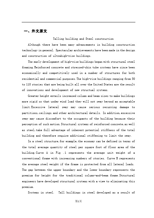
一、外文原文Talling building and Steel construction Although there have been many advancements in building construction technology in general. Spectacular archievements have been made in the design and construction of ultrahigh-rise buildings.The early development of high-rise buildings began with structural steel framing.Reinforced concrete and stressed-skin tube systems have since been economically and competitively used in a number of structures for both residential and commercial purposes.The high-rise buildings ranging from 50 to 110 stories that are being built all over the United States are the result of innovations and development of new structual systems.Greater height entails increased column and beam sizes to make buildings more rigid so that under wind load they will not sway beyond an acceptable limit.Excessive lateral sway may cause serious recurring damage to partitions,ceilings.and other architectural details. In addition,excessive sway may cause discomfort to the occupants of the building because their perception of such motion.Structural systems of reinforced concrete,as well as steel,take full advantage of inherent potential stiffness of the total building and therefore require additional stiffening to limit the sway.In a steel structure,for example,the economy can be defined in terms of the total average quantity of steel per square foot of floor area of the building.Curve A in Fig .1 represents the average unit weight of a conventional frame with increasing numbers of stories. Curve B represents the average steel weight if the frame is protected from all lateral loads. The gap between the upper boundary and the lower boundary represents the premium for height for the traditional column-and-beam frame.Structural engineers have developed structural systems with a view to eliminating this premium.Systems in steel. Tall buildings in steel developed as a result ofseveral types of structural innovations. The innovations have been applied to the construction of both office and apartment buildings.Frame with rigid belt trusses. In order to tie the exterior columns of a frame structure to the interior vertical trusses,a system of rigid belt trusses at mid-height and at the top of the building may be used. A good example of this system is the First Wisconsin Bank Building(1974) in Milwaukee.Framed tube. The maximum efficiency of the total structure of a tall building, for both strength and stiffness,to resist wind load can be achieved only if all column element can be connected to each other in such a way that the entire building acts as a hollow tube or rigid box in projecting out of the ground. This particular structural system was probably used for the first time in the 43-story reinforced concrete DeWitt Chestnut Apartment Building in Chicago. The most significant use of this system is in the twin structural steel towers of the 110-story World Trade Center building in New York Column-diagonal truss tube. The exterior columns of a building can be spaced reasonably far apart and yet be made to work together as a tube by connecting them with diagonal members interesting at the centre line of the columns and beams. This simple yet extremely efficient system was used for the first time on the John Hancock Centre in Chicago, using as much steel as is normally needed for a traditional 40-story building.Bundled tube. With the continuing need for larger and taller buildings, the framed tube or the column-diagonal truss tube may be used in a bundled form to create larger tube envelopes while maintaining high efficiency. The 110-story Sears Roebuck Headquarters Building in Chicago has nine tube, bundled at the base of the building in three rows. Some of these individual tubes terminate at different heights of the building, demonstrating the unlimited architectural possibilities of this latest structural concept. The Sears tower, at a height of 1450 ft(442m), is the world’s tallest building.Stressed-skin tube system. The tube structural system was developed for improving the resistance to lateral forces (wind and earthquake) and thecontrol of drift (lateral building movement ) in high-rise building. The stressed-skin tube takes the tube system a step further. The development of the stressed-skin tube utilizes the façade of the building as a structural element which acts with the framed tube, thus providing an efficient way of resisting lateral loads in high-rise buildings, and resulting in cost-effective column-free interior space with a high ratio of net to gross floor area.Because of the contribution of the stressed-skin façade, the framed members of the tube require less mass, and are thus lighter and less expensive. All the typical columns and spandrel beams are standard rolled shapes,minimizing the use and cost of special built-up members. The depth requirement for the perimeter spandrel beams is also reduced, and the need for upset beams above floors, which would encroach on valuable space, is minimized. The structural system has been used on the 54-story One Mellon Bank Center in Pittburgh.Systems in concrete. While tall buildings constructed of steel had an early start, development of tall buildings of reinforced concrete progressed at a fast enough rate to provide a competitive chanllenge to structural steel systems for both office and apartment buildings.Framed tube. As discussed above, the first framed tube concept for tall buildings was used for the 43-story DeWitt Chestnut Apartment Building. In this building ,exterior columns were spaced at 5.5ft (1.68m) centers, and interior columns were used as needed to support the 8-in . -thick (20-m) flat-plate concrete slabs.Tube in tube. Another system in reinforced concrete for office buildings combines the traditional shear wall construction with an exterior framed tube. The system consists of an outer framed tube of very closely spaced columns and an interior rigid shear wall tube enclosing the central service area. The system known as the tube-in-tube system , made it possible to design the world’s present tallest (714ft or 218m)lightweight concrete bu ilding( the 52-story One Shell Plaza Building in Houston) for the unit price of a traditional shear wall structure of only 35 stories.Systems combining both concrete and steel have also been developed, an examle of which is the composite system developed by skidmore, Owings &Merril in which an exterior closely spaced framed tube in concrete envelops an interior steel framing, thereby combining the advantages of both reinforced concrete and structural steel systems. The 52-story One Shell Square Building in New Orleans is based on this system.Steel construction refers to a broad range of building construction in which steel plays the leading role. Most steel construction consists of large-scale buildings or engineering works, with the steel generally in the form of beams, girders, bars, plates, and other members shaped through the hot-rolled process. Despite the increased use of other materials, steel construction remained a major outlet for the steel industries of the U.S, U.K, U.S.S.R, Japan, West German, France, and other steel producers in the 1970s.二、原文翻译高层结构与钢结构近年来,尽管一般的建筑结构设计取得了很大的进步,但是取得显著成绩的还要属超高层建筑结构设计。
土木外文翻译原文和译文
A convection-conduction model for analysis of thefreeze-thawconditions in the surrounding rock wall of atunnel in permafrost regionsAbstractBased on the analyses of fundamental meteorological and hydrogeological conditions at the site of a tunnel in the cold regions, a combined convection-conduction model for air flow in the tunnel and temperature field in the surrounding has been constructed. Using the model, the air temperature distribution in the Xiluoqi No. 2 Tunnel has been simulated numerically. The simulated results are in agreement with the data observed. Then, based on the in situ conditions of sir temperature, atmospheric pressure, wind force, hydrogeology and engineering geology, the air-temperature relationship between the temperature on the surface of the tunnel wall and the air temperature at the entry and exit of the tunnel has been obtained, and the freeze-thaw conditions at the Dabanshan Tunnel which is now under construction is predicted.Keywords: tunnel in cold regions, convective heat exchange and conduction, freeze-thaw.A number of highway and railway tunnels have been constructed in the permafrost regions and their neighboring areas in China. Since the hydrological and thermal conditions changed after a tunnel was excavated,the surrounding wall rock materials often froze, the frost heaving caused damage to the liner layers and seeping water froze into ice diamonds,which seriously interfered with the communication and transportation. Similar problems of the freezing damage in the tunnelsalso appeared in other countries like Russia, Norway and Japan .Hence it is urgent to predict the freeze-thaw conditions in the surrounding rock materials and provide a basis for the design,construction and maintenance of new tunnels in cold regions.Many tunnels,constructed in cold regions or their neighbouring areas,pass through the part beneath the permafrost base .After a tunnel is excavated,the original thermodynamical conditions in the surroundings are and thaw destroyed and replaced mainly by the air connections without the heat radiation, the conditions determined principally by the temperature and velocity of air flow in the tunnel,the coefficients of convective heat transfer on the tunnel wall,and the geothermal heat. In order to analyze and predict the freeze and thaw conditions of the surrounding wall rock of a tunnel,presuming the axial variations of air flow temperature and the coefficients of convective heat transfer, Lunardini discussed the freeze and thaw conditions by the approximate formulae obtained by Sham-sundar in study of freezing outside a circular tube with axial variations of coolant temperature .We simulated the temperature conditions on the surface of a tunnel wall varying similarly to the periodic changes of the outside air temperature .In fact,the temperatures of the air and the surrounding wall rock material affect each other so we cannot find the temperature variations of the air flow in advance; furthermore,it is difficult to quantify the coefficient of convective heat exchange at the surface of the tunnel wall .Therefore it is not practicable to define the temperature on the surface of the tunnel wall according to the outside air temperature .In this paper, we combine the air flow convective heat ex-change and heat conduction in the surrounding rock material into one model,and simulate the freeze-thaw conditions of the surrounding rock material based on the in situ conditions of air temperature,atmospheric pressure,wind force at the entry and exit of the tunnel,and the conditions of hydrogeology and engineering geology.重庆交通大学土木工程专业(隧道与城市轨道交通工程方向)毕业设计外文翻译Mathematical modelIn order to construct an appropriate model, we need the in situ fundamental conditions as a ba-sis .Here we use the conditions at the scene of the Dabanshan Tunnel. The Dabanshan Tunnel is lo-toted on the highway from Xining to Zhangye, south of the Datong River, at an elevation of 3754.78-3 801.23 m, with a length of 1 530 m and an alignment from southwest to northeast. The tunnel runs from the southwest to the northeast.Since the monthly-average air temperature is beneath 0`}C for eight months at the tunnel site each year and the construction would last for several years,the surrounding rock materials would become cooler during the construction .We conclude that, after excavation, the pattern of air flow would depend mainly on the dominant wind speed at the entry and exit,and the effects of the temperature difference between the inside and outside of the tunnel would be very small .Since the dominant wind direction is northeast at the tunnel site in winter, the air flow in the tunnel would go from the exit to the entry. Even though the dominant wind trend is southeastly in summer, considering the pressure difference, the temperature difference and the topography of the entry and exit,the air flow in the tunnel would also be from the exit to entry .Additionally,since the wind speed at the tunnel site is low,we could consider that the air flow would be principally laminar.Based on the reasons mentioned,we simplify the tunnel to a round tube,and consider that theair flow and temperature are symmetrical about the axis of the tunnel,Ignoring the influence of the air temperature on the speed of air flow, we obtain the following equation:where t ,x ,r are the time ,axial and radial coordinates; U ,V are axial and radial wind speeds; T is temperature; p is the effective pressure(that is ,air pressure divided by air density); v is the kinematic viscosity of air; a is the thermal conductivity of air; L is the length of the tunnel; R is the equivalent radius of the tunnel section; D is the length of time after the tunnel construction;,f S (t), u S (t) are frozen and thawed parts in the surrounding rock materials respectively; f λ,u λand f C ,u C are thermal conductivities and volumetric thermal capacities in frozen and thawed parts respectively; X= (x , r),ξ(t) is phase change front; Lh is heat latent of freezing water; and To is critical freezing temperature of rock ( here we assume To= -0.1℃).2 used for solving the modelEquation(1)shows flow. We first solve those concerning temperature at that the temperature of the surrounding rock does not affect the speed of air equations concerning the speed of air flow, and then solve those equations every time elapse.2. 1 Procedure used for solving the continuity and momentum equations重庆交通大学土木工程专业(隧道与城市轨道交通工程方向)毕业设计外文翻译Since the first three equations in(1) are not independent we derive the second equation by xand the third equation by r. After preliminary calculation we obtain the following elliptic equation concerning the effective pressure p:Then we solve equations in(1) using the following procedures:(i ) Assume the values for U0,V0;( ii ) substituting U0,V0 into eq. (2),and solving (2),we obtain p0;(iii) solving the first and second equations of(1),we obtain U0,V1;(iv) solving the first and third equations of(1),we obtain U2,V2; (v) calculating the momentum-average of U1,v1 and U2,v2,we obtain the new U0,V0;then return to (ii);(vi) iterating as above until the disparity of those solutions in two consecutive iterations is sufficiently small or is satisfied,we then take those values of p0,U0 and V0 as the initial values for the next elapse and solve those equations concerning the temperature..2 .2 Entire method used for solving the energy equationsAs mentioned previously,the temperature field of the surrounding rock and the air flow affect each other. Thus the surface of the tunnel wall is both the boundary of the temperature field in the surrounding rock and the boundary of the temperature field in air flow .Therefore, it is difficult to separately identify the temperature on the tunnel wall surface,and we cannot independently solve those equations concerning the temperature of air flow and those equations concerning the temperature of the surrounding rock .In order to cope with this problem,we simultaneously solve the two groups of equations based on the fact that at the tunnel wall surface both temperatures are equal .We should bearin mind the phase change while solving those equations concerning the temperature of the surrounding rock ,and the convection while solving those equations concerning the temperature of the air flow, and we only need to smooth those relative parameters at the tunnel wall surface .The solving methods for the equations with the phase change are the same as in reference [3].2.3 Determination of thermal parameters and initial and boundaryconditions2.3.1 Determination of the thermal parameters. Using p= 1013.25-0.1088 H ,we calculateair pressure p at elevation H and calculate the air density ρ using formula GTP =ρ, where T is the yearly-average absolute air temperature ,and G is the humidity constant of air. Letting P C be the thermal capacity with fixed pressure, λ the thermal conductivity ,and μ the dynamic viscosity of air flow, we calculate the thermal conductivity and kinematic viscosity using the formulas ρλP C =a and ρμν=. The thermal parameters of the surrounding rock are determined from the tunnel site.2 .3.2 Determination of the initial and boundary conditions .Choose the observed monthly average wind speed at the entry and exit as boundary conditions of wind speed ,and choose the relative effective pressure p=0 at the exit ( that is ,the entry of the dominant wind trend) and ]5[22/)/1(v d kL p ⨯+= on the section of entry ( that is ,the exit of the dominant wind trend ),where k is the coefficient of resistance along the tunnel wall, d = 2R ,and v is the axial average speed. We approximate T varying by the sine law according to the data observed at the scene and provide a suitable boundary value based on the position of the permafrost base and the geothermal gradient of the thaw rock materials beneath the重庆交通大学土木工程专业(隧道与城市轨道交通工程方向)毕业设计外文翻译permafrost base.3 A simulated exampleUsing the model and the solving method mentioned above,we simulate the varying law of the air temperature in the tunnel along with the temperature at the entry and exit of the Xiluoqi No.2 Tunnel .We observe that the simulated results are close to the data observed[6].The Xiluoqi No .2 Tunnel is located on the Nongling railway in northeastern China and passes through the part beneath the permafrost base .It has a length of 1 160 m running from the northwest to the southeast, with the entry of the tunnel in the northwest,and the elevation is about 700 m. The dominant wind direction in the tunnel is from northwest to southeast, with a maximum monthly-average speed of 3 m/s and a minimum monthly-average speed of 1 .7 m/s . Based on the data observed,we approximate the varying sine law of air temperature at the entry and exit with yearly averages of -5℃,-6.4℃ and amplitudes of 18.9℃ and 17.6℃respectively. The equivalent diameter is 5 .8m,and the resistant coefficient along the tunnel wall is 0.025.Since the effect of the thermal parameter of the surrounding rock on the air flow is much smaller than that of wind speed,pressure and temperature at the entry and exit,we refer to the data observed in the Dabanshan Tunnel for the thermal parameters.Figure 1 shows the simulated yearly-average air temperature inside and at the entry and exit of the tunnel compared with the data observed .We observe that the difference is less than 0 .2 `C from the entry to exit.Figure 2 shows a comparison of the simulated and observed monthly-average air temperature in-side (distance greater than 100 m from the entry and exit) the tunnel. We observe that the principal law is almost the same,and the main reason for the difference is the errors that came from approximating the varying sine law at the entry and exit; especially , the maximum monthly-average air temperature of 1979 was not for July but for August.Fig.1. Comparison of simulated and observed air temperature in Xiluoqi No.2 Tunnel in 1979.1,simulated values;2,observed valuesFig.2.The comparison of simulated and observed air temperature inside The Xiluoqi No.2 Tunnel in 1979.1,simulated values;2,observed values4 Prediction of the freeze-thaw conditions for the Dabanshan Tunnel 4 .1 Thermal parameter and initial and boundary conditionsUsing the elevation of 3 800 m and the yearly-average air temperature of -3℃, we calculate the air density p=0 .774 kg/m 3.Since steam exists In the air, we choose the thermal capacity with a fixed pressure of air ),./(8744.10C kg kJ C p = heat conductivity )./(100.202C m W -⨯=λ andand the dynamic viscosity )../(10218.96s m kg -⨯=μ After calculation we obtain the thermal diffusivity a= 1 .3788s m /1025-⨯ and the kinematic viscosity ,s m /1019.125-⨯=ν .Considering that the section of automobiles is much smaller than that of the tunnel and the auto-mobiles pass through the tunnel at a low speed ,we ignore the piston effects ,coming from the movement of automobiles ,in the diffusion of the air.We consider the rock as a whole component and choose the dry volumetric cavity 3/2400m kg d =λ,content of water and unfrozen water W=3% and W=1%, and the thermal conductivity c m W o u ./9.1=λ,c m W o f ./0.2=λ,heat重庆交通大学土木工程专业(隧道与城市轨道交通工程方向)毕业设计外文翻译capacityc kg kJ C o V ./8.0= and d u f W w C γ⨯++=1)128.48.0(,d u u Ww C γ⨯++=1)128.48.0( According to the data observed at the tunnel site ,the maximum monthly-average wind speed is about 3 .5 m/s ,and the minimum monthly-average wind speed is about 2 .5 m/s .We approximate the wind speed at the entry and exit as )/](5.2)7(028.0[)(2s m t t v +-⨯=, where t is in month. The initial wind speed in the tunnel is set to be.0),,0(),)(1(),,0(2=-=r x V R r U r x U a The initial and boundary values of temperature T are set to bewhere f(x) is the distance from the vault to the permafrost base ,and R0=25 m is the radius of do-main of solution T. We assume that the geothermal gradient is 3%,the yearly-average air temperature outside tunnel the is A=-3C 0,and the amplitude is B=12C 0.As for the boundary of R=Ro ,we first solve the equations considering R=Ro as the first type of boundary; that is we assume that T=f(x)⨯3%C 0on R=Ro. We find that, after one year, the heat flow trend will have changed in the range of radius between 5 and 25m in the surrounding rock.. Considering that the rock will be cooler hereafter and it will be affected yet by geothermal heat, we appoximately assume that the boundary R=Ro is the second type of boundary; that is ,we assume that the gradient value ,obtained from the calculation up to the end of the first year after excavation under the first type of boundary value, is the gradient on R=Ro of T.Considering the surrounding rock to be cooler during the period of construction ,we calculatefrom January and iterate some elapses of time under the same boundary. Then we let the boundaryvalues vary and solve the equations step by step(it can be proved that the solution will not depend on the choice of initial values after many time elapses ).1)The yearly-average temperature on the surface wall of the tunnel is approximately equal to the ai4 .2 Calculated resultsFigures 3 and 4 show the variations of the monthly-average temperatures on the surface of the tunnel wall along with the variations at the entry and exit .Figs .5 and 6 show the year when permafrost begins to form and the maximum thawed depth after permafrost formed in different surrounding sections.Fig.3.The monthly-average temperature parison of the monthly- On the surface of Dabanshan Tunnel.I, average temperature on the surface The month,I=1,2,3,,,12 tunnel with that outside the tunnel. 1,inner temperature on the surface ;2,outside air temperatureFig.5.The year when permafrost Fig.6.The maximum thawed depth after Begins to from in different permafrost formed in different years Sections of the surroundingrock重庆交通大学土木工程专业(隧道与城市轨道交通工程方向)毕业设计外文翻译4 .3 Preliminary conclusionBased on the initial-boundary conditions and thermal parameters mentioned above, we obtain the following preliminary conclusions: r temperature at the entry and exit. It is warmer during the cold season and cooler during the warm season in the internal part (more than 100 m from the entry and exit) of the tunnel than at the entry and exit . Fig .1 shows that the internal monthly-average temperature on the surface of the tunnel wall is 1.2℃ higher in January, February and December, 1℃higher in March and October, and 1 .6℃ lower in June and August, and 2qC lower in July than the air temperature at the entry and exit. In other months the infernal temperature on the surface of the tunnel wall approximately equals the air temperature at the entry and exit.2) Since it is affected by the geothermal heat in the internal surrounding section,especially in the central part, the internal amplitude of the yearly-average temperature on the surface of the tunnel wall decreases and is 1 .6℃ lower than that at the entry and exit.3 ) Under the conditions that the surrounding rock is compact , without a great amount of under-ground water, and using a thermal insulating layer(as designed PU with depth of 0.05 m and heat conductivity λ=0.0216 W/m℃,FBT with depth of 0.085 m and heat conductivity λ=0.0517W/m℃),in the third year after tunnel construction,the surrounding rock will begin to form permafrost in the range of 200 m from the entry and exit .In the first and the second year after construction, the surrounding rock will begin to form permafrost in the range of 40 and 100m from the entry and exit respectively .In the central part,more than 200m from the entry and exit, permafrost will begin to form in the eighth year. Near the center of the tunnel,permafrost will appear in the 14-15th years. During the first and second years after permafrost formed,the maximum of annual thawed depth is large (especially in the central part of the surrounding rock section) and thereafter it decreases every year. The maximum of annual thawed depth will be stable until the 19-20th yearsand will remain in s range of 2-3 m.4) If permafrost forms entirely in the surrounding rock,the permafrost will provide a water-isolating layer and be favourable for communication and transportation .However, in the process of construction,we found a lot of underground water in some sections of the surrounding rock .It will permanently exist in those sections,seeping out water and resulting in freezing damage to the liner layer. Further work will be reported elsewhere.重庆交通大学土木工程专业(隧道与城市轨道交通工程方向)毕业设计外文翻译严寒地区隧道围岩冻融状况分析的导热与对流换热模型摘要通过对严寒地区隧道现场基本气象条件的分析,建立了隧道内空气与围岩对流换热及固体导热的综合模型;用此模型对大兴安岭西罗奇2号隧道的洞内气温分布进行了模拟计算,结果与实测值基本一致;分析预报了正在开凿的祁连山区大坂山隧道开通运营后洞内温度及围岩冻结、融化状况.关键词严寒地区隧道导热与对流换热冻结与融化在我国多年冻土分布及邻近地区,修筑了公路和铁路隧道几十座.由于隧道开通后洞内水热条件的变化;,普遍引起洞内围岩冻结,造成对衬砌层的冻胀破坏以及洞内渗水冻结成冰凌等,严重影响了正常交通.类似隧道冻害问题同样出现在其他国家(苏联、挪威、日本等)的寒冷地区.如何预测分析隧道开挖后围岩的冻结状况,为严寒地区隧道建设的设计、施工及维护提供依据,这是一个亟待解决的重要课题.在多年冻土及其临近地区修筑的隧道,多数除进出口部分外从多年冻土下限以下岩层穿过.隧道贯通后,围岩内原有的稳定热力学条件遭到破坏,代之以阻断热辐射、开放通风对流为特征的新的热力系统.隧道开通运营后,围岩的冻融特性将主要由流经洞内的气流的温度、速度、气—固交界面的换热以及地热梯度所确定.为分析预测隧道开通后围岩的冻融特性,Lu-nardini借用Shamsundar研究圆形制冷管周围土体冻融特性时所得的近似公式,讨论过围岩的冻融特性.我们也曾就壁面温度随气温周期性变化的情况,分析计算了隧道围岩的温度场[3].但实际情况下,围岩与气体的温度场相互作用,隧道内气体温度的变化规律无法预先知道,加之洞壁表面的换热系数在技术上很难测定,从而由气温的变化确定壁面温度的变化难以实现.本文通过气一固祸合的办法,把气体、固体的换热和导热作为整体来处理,从洞口气温、风速和空气湿度、压力及围岩的水热物理参数等基本数据出发,计算出围岩的温度场.1数学模型为确定合适的数学模型,须以现场的基本情况为依据.这里我们以青海祁连山区大坂山公路隧道的基本情况为背景来加以说明.大坂山隧道位于西宁一张业公路大河以南,海拔3754.78~3801.23 m ,全长1530 m ,隧道近西南—东北走向. 由于大坂山地区隧道施工现场平均气温为负温的时间每年约长8个月,加之施工时间持续数年,围岩在施土过程中己经预冷,所以隧道开通运营后,洞内气体流动的形态主要由进出口的主导风速所确定,而受洞内围岩地温与洞外气温的温度压差的影响较小;冬季祁连山区盛行西北风,气流将从隧道出曰流向进口端,夏季虽然祁连山区盛行东偏南风,但考虑到洞口两端气压差、温度压差以及进出口地形等因素,洞内气流仍将由出口北端流向进口端.另外,由于现场年平均风速不大,可以认为洞内气体将以层流为主基于以上基本情况,我们将隧道简化成圆筒,并认为气流、温度等关十隧道中心线轴对称,忽略气体温度的变化对其流速的影响,可有如下的方程:其中t 为时间,x 为轴向坐标,r 为径向坐标;U, V 分别为轴向和径向速度,T 为温度,P 为有效压力(即空气压力与空气密度之比少,V 为空气运动粘性系数,a 为空气的导温系数,L 为隧道长度,R 为隧道的当量半径,D 为时间长度)(t S f , )(t S u 分别为围岩的冻、融区域. f λ,u λ分别为冻、融状态下的热传导系数,f C ,u C 分别为冻、融状态下的体积热容量,X=(x,r) , )(t ξ为冻、融相变界面,To 为岩石冻结临界温度(这里具体计算时取To=-0.10C 0),h L 为水的相变潜热.重庆交通大学土木工程专业(隧道与城市轨道交通工程方向)毕业设计外文翻译2 求解过程由方程(1)知,围岩的温度的高低不影响气体的流动速度,所以我们可先解出速度,再解温度.2.1 连续性方程和动量方程的求解由于方程((1)的前3个方程不是相互独立的,通过将动量方程分别对x 和r 求导,经整理化简,我们得到关于压力P 的如下椭圆型方程:于是,对方程(1)中的连续性方程和动量方程的求解,我们按如下步骤进行:(1)设定速度0U ,0V ;( 2)将0U ,0V 代入方程并求解,得0P(3)联立方程(1)的第一个和第二个方程,解得一组解1U ,1V ;(4)联立方程((1)的第一个和第三个方程,解得一组解2U ,2V ;(5)对((3) ,(4)得到的速度进行动量平均,得新的0U ,0V 返回(2) ;(6)按上述方法进行迭代,直到前后两次的速度值之差足够小.以0P ,0U ,0V 作为本时段的解,下一时段求解时以此作为迭代初值.2. 2 能量方程的整体解法如前所述,围岩与空气的温度场相互作用,壁面既是气体温度场的边界,又是固体温度场的边界,壁面的温度值难以确定,我们无法分别独立地求解隧道内的气体温度场和围岩温度场.为克服这一困难,我们利用在洞壁表面上,固体温度等于气体温度这一事实,把隧道内气体的温度和围岩内固体的温度放在一起求解,这样壁面温度将作为末知量被解出来.只是需要注意两点:解流体温度场时不考虑相变和解固体温度时没有对流项;在洞壁表面上方程系数的光滑化.另外,带相变的温度场的算法与文献[3]相同.2. 3热参数及初边值的确定热参数的确定方法: 用p=1013.25-0.1088H 计算出海拔高度为H 的隧道现场的大气压强,再由GT P =ρ计算出现场空气密度ρ,其中T 为现场大气的年平均绝对温度,G 为空气的气体常数.记定压比热为P C ,导热系数为λ,空气的动力粘性系数为μ.按ρλP C =a 和ρμν= 计算空气的导温系数和运动粘性系数.围岩的热物理参数则由现场采样测定.初边值的确定方法:洞曰风速取为现场观测的各月平均风速.取卞导风进曰的相对有效气压为0,主导风出口的气压则取为]5[22/)/1(v d kL p ⨯+=,这里k 为隧道内的沿程阻力系数,L 为隧道长度,d 为隧道端面的当量直径,ν为进口端面轴向平均速度.进出口气温年变化规律由现场观测资料,用正弦曲线拟合,围岩内计算区域的边界按现场多年冻土下限和地热梯度确定出适当的温度值或温度梯度. 3 计算实例按以上所述的模型及计算方法,我们对大兴安岭西罗奇2号隧道内气温随洞曰外气温变化的规律进行了模拟计算验证,所得结果与实测值[6]相比较,基本规律一致.西罗奇2号隧道是位十东北嫩林线的一座非多年冻土单线铁路隧道,全长1160 m ,隧道近西北一东南向,高洞口位于西北向,冬季隧道主导风向为西北风.洞口海拔高度约为700 m ,月平均最高风速约为3m/s,最低风速约为1.7m/s.根据现场观测资料,我们将进出口气温拟合为年平均分别为-5C 0和-6.4C 0,年变化振幅分别为18.9C 0和17.6C 0的正弦曲线.隧道的当量直径为5.8 m,沿程阻力系数取为0.025.由于围岩的热物理参数对计算洞内气温的影响远比洞口的风速、压力及气温的影响小得多,我们这里参考使用了大坂山隧道的资料.图1给出了洞口及洞内年平均气温的计算值与观测值比较的情况,从进口到出口,两值之差都小于0.2C 0.图2给出了洞内 (距进出口l00m 以上)月平均气温的计算值与观测值比较的情况,可以看出温度变化的基本规律完全一致,造成两值之差的主要原因是洞口气温年变化规律之正弦曲线的拟合误差,特别是1979年隧道现场月平均最高气温不是在7月份,而是在8月份.重庆交通大学土木工程专业(隧道与城市轨道交通工程方向)毕业设计外文翻译图1. 比较1979年在西罗奇周家山2号隧道仿真试验与观察的空气温度.1、模拟值;2、观测值图2。
土木工程外文翻译(中英互译版)
使用加固纤维聚合物增强混凝土梁的延性Nabil F. Grace, George Abel-Sayed, Wael F. Ragheb摘要:一种为加强结构延性的新型单轴柔软加强质地的聚合物(FRP)已在被研究,开发和生产(在结构测试的中心在劳伦斯技术大学)。
这种织物是两种碳纤维和一种玻璃纤维的混合物,而且经过设计它们在受拉屈服时应变值较低,从而表达出伪延性的性能。
通过对八根混凝土梁在弯曲荷载作用下的加固和检测对研制中的织物的效果和延性进行了研究。
用现在常用的单向碳纤维薄片、织物和板进行加固的相似梁也进行了检测,以便同用研制中的织物加固梁进行性能上的比拟。
这种织物经过设计具有和加固梁中的钢筋同时屈服的潜力,从而和未加固梁一样,它也能得到屈服台阶。
相对于那些用现在常用的碳纤维加固体系进行加固的梁,这种研制中的织物加固的梁承受更高的屈服荷载,并且有更高的延性指标。
这种研制中的织物对加固机制表达出更大的奉献。
关键词:混凝土,延性,纤维加固,变形介绍外贴粘合纤维增强聚合物〔FRP〕片和条带近来已经被确定是一种对钢筋混凝土结构进行修复和加固的有效手段。
关于应用外贴粘合FRP板、薄片和织物对混凝土梁进行变形加固的钢筋混凝土梁的性能,一些试验研究调查已经进行过报告。
Saadatmanesh和Ehsani〔1991〕检测了应用玻璃纤维增强聚合物(GFRP)板进行变形加固的钢筋混凝土梁的性能。
Ritchie等人〔1991〕检测了应用GFRP,碳纤维增强聚合物〔CFRP〕和G/CFRP板进行变形加固的钢筋混凝土梁的性能。
Grace等人〔1999〕和Triantafillou〔1992〕研究了应用CFRP薄片进行变形加固的钢筋混凝土梁的性能。
Norris,Saadatmanesh和Ehsani〔1997〕研究了应用单向CFRP薄片和CFRP织物进行加固的混凝土梁的性能。
在所有的这些研究中,加固的梁比未加固的梁承受更高的极限荷载。
土木专业外文翻译3
DamA dam is a structure built across, river, or estuary to retain water. Its purposes are to meet demands for water for human consumption, irrigation, or industry; to reduce peak discharge of flood water; to increase available water stored for generating hydroelectric power; or to increase the depth of water in a river so as to improve navigation. An incidental purpose can be to propose can be to provide a lake for recreation.Auxiliary works at a dam may include spillways, gates, or valves to control the discharge of surplus water downstream form the dam; an intake structure conducting water to power station or to canals, tunnels, or pipelines for more distant use; provision for evacuating silt carried into the reservoir; and means for permitting ships or fish to pass the dam. A dam therefore is the central structure in a multipurpose scheme aiming at the conservation of water resources. The multipurpose dam holds special importance in the underdeveloped counties, where a small nation may reap enormous benefits in agriculture and industry from a single dam.Dams fall into several distinct classes, by profile and by building material. The decision as to which type of dam be build depends largely on the foundation conditions in the valley and the construction materials available. Basically, the choice of materials now lies between concrete, soils, and rockfill. Though a number of dams were built in the past of jointed masonry, this practice is now largely obsolete, The monolithic form of concrete dams permits greater variations in profile, according to the extent water pressure is resisted by the deadweight of the structure, is transferred laterally to buttresses, or is carried by horizontal arching across the valley to abutments formed by the sides of the valley.Basic Problems in Dam DesignMost modern dams continue to be of two basic types: masonry (concrete) and embankment (earthfill). Masonry dams are typically used to block streams running through narrow gorges, as in mountainous terrain; though such dams may be very high, the total amount of material required is limited. Embankment dams sre preferred to control broad streams, where only avery large barrier, requiring a great volume of material, will suffice. The choice of masonry or embankment and the precise design depend on the geology and configuration of the site, the functions of the dam, and cost factors.Site investigation and testing. Investigation of a site for a dam includes sinking trial borings to determine the strata. The borings are supplemented by shafts and tunnels which, because of their cost, must be used as sparingly as possible. In the shafts and tunnels, tests can be made to measure strength, elasticity, permeability, and prevailing stresses in strata, with particular attention given to the properties of thin partings, or walls, between the more massive beds, The presence in groundwater of chemical solutions harmful to the materials to be used in the construction of the dam must be assessed. Sources of construction materials need exploration. As dams continue to increase in height, the study of foundation conditions becomes increasingly critical.Models are particularly useful in analysis of arch dams and in verifying analytical stress calculations. Various materials have been used for model tests; on some early tests for Hoover Dam, rubber was employed. The need for accurate reproduction of stress patterns in complex models is met by using material of low elasticity. In a sense, dams themselves are models for future design. The instruments built into them to record movements under load, strains within materials after construction, temperature and pressure changes, and other factors are installed primarily to study the performance of the structure and to warn of possible emergencies, but their value in confirming design assumptions is important.The digital computer has permitted considerable advance in analytical methods of design. Its ability to handle a great volume of data and to solve large sets of simultaneous equations containing many variables ha made practicable the method of Finite Element Analysis. In this method, a complicated structure is divided into a number of separate equilibrium conditions, and strains are rendered compatible, thus leading to a complete analysis of stress and strain distribution throughout the structure.Problems of materials. Each of the two basic dam materials, concrete and earth or rock fill, has a weakness that must be overcome by the proper design of the dam.Weaknesses of concrete.. Concrete is weak in tensile strength; that is, it can be pulled aparteasily. Concrete dams must therefore be designed to place minimum tensile strain on the dam and to make use of concrete’s great compressive strength, or ability to support vertical loads. The chief constituent of concrete, cement, shrinks as it sets and hardens, due to water absorption in the crystalline structure, to evaporation of water to the atmosphere, and to cooling form the higher temperatures reached when the chemical reactions in the cement are in progress during hydration. Because of the large volume of concrete in a dam, shrinkage presents a serious cracking hazard.Various expedients are used to overcome the problem. Concrete is usually cast in separate blocks of limited height. Gaps may be left to permit heat losses and filled in later. Low-heat cements may be used; these are specially blended so that rates of heat evolution are retarded. Cement content can be safely reduced in the interior concrete in the dam, in which strength and resistance to climatic and chemical deterioration are less important. The cement content, and therefore the heat caused by hydrating, can also be reduced by using aggregate (the other major constituent of concrete) of larger stones. Another expedient is to use other fine-grained materials, such as fly ash (pulverized fuel), as filler, reducing the total cement volume in the concrete. Another is to use certain additives, surface-active agents, and air-entraining agents that permit using a lower water-to-cement ratio in mix by ice, circulating water through pipes laid in the concrete, and extracting excess water from surfaces by vacuum.Weaknesses of earth and rock fill. Soils and rock fragments lack the strength of concrete, are much more permeable, and possess less resistance to deterioration and disturbance by flowing water. These disadvantages are compensated for by a much lower cost and by the ability of earth fill to adapt to deformation caused by movements in the dam foundation. This assumes, of course, sufficient usable soil available close to the dam site. In bare mountain country it may be necessary to quarry rock and construct a rockfill rather than an rarthfill dam. Earth fill is of course more economical, and often a suitable borrow area can be found close to the site. Soil consists of solid particles with water and air in between. When the soil is compressed by loading, as occurs in dam construction, some drainage of air and water takes place, causing an increase in pressures between the solid particles. When there is a high rate of seepage, the soil tends to develop differential pressures and reach a condition called quick, in which it behavesas a fluid. Even if it does not reach this condition, there is often some weakening of its structure, and steps must be taken to counter this.The earthquake problem. Many large dams have been built in the seismically active regions of the world, including Japan, the western United States, New Zealand, the Himalayas, and the Middle East. In 1968, the Tokachi earthquake damaged 93 dams in Honshu, the main Japanese Island; all were embankment dams of relatively small height.Despite a great deal of work on the distribution of seismic activity, the measurement of strong ground motions, and the response of dams to such motions, earthquake design of dams remains imprecise. The characteristics of strong ground motions at a given site cannot be predicted, and all types of dams possess some degree of freedom, imperfect elasticity, and imprecise damping. Nevertheless, the digital computer and model testing have given promise of considerable progress. It is now possible calculate the response of a concrete dam to any specified ground motion; this has been done for the Tang-e Soleyman Dam in Iran and the Hendrik Verwoerd Dam in South Africa.There has also been considerable advance in the theoretical estimation of the effects of ground motion on embankment dams.坝大坝是横跨在溪流,河流或河口之间用于储水的建筑物。
土木工程 专业外语词汇大全中英翻译
土木工程专业外语词汇大全中英翻译1. 综合类大地工程geotechnical engineering1. 综合类反分析法back analysis method1. 综合类基础工程foundation engineering1. 综合类临界状态土力学critical state soil mechanics1. 综合类数值岩土力学numerical geomechanics1. 综合类土soil, earth1. 综合类土动力学soil dynamics1. 综合类土力学soil mechanics1. 综合类岩土工程geotechnical engineering1. 综合类应力路径stress path1. 综合类应力路径法stress path method2. 工程地质及勘察变质岩metamorphic rock2. 工程地质及勘察标准冻深standard frost penetration2. 工程地质及勘察冰川沉积glacial deposit2. 工程地质及勘察冰积层(台)glacial deposit2. 工程地质及勘察残积土eluvial soil, residual soil2. 工程地质及勘察层理beding2. 工程地质及勘察长石feldspar2. 工程地质及勘察沉积岩sedimentary rock2. 工程地质及勘察承压水confined water2. 工程地质及勘察次生矿物secondary mineral2. 工程地质及勘察地质年代geological age2. 工程地质及勘察地质图geological map2. 工程地质及勘察地下水groundwater2. 工程地质及勘察断层fault2. 工程地质及勘察断裂构造fracture structure2. 工程地质及勘察工程地质勘察engineering geological exploration 2. 工程地质及勘察海积层(台)marine deposit2. 工程地质及勘察海相沉积marine deposit2. 工程地质及勘察花岗岩granite2. 工程地质及勘察滑坡landslide2. 工程地质及勘察化石fossil2. 工程地质及勘察化学沉积岩chemical sedimentary rock2. 工程地质及勘察阶地terrace2. 工程地质及勘察节理joint2. 工程地质及勘察解理cleavage2. 工程地质及勘察喀斯特karst2. 工程地质及勘察矿物硬度hardness of minerals2. 工程地质及勘察砾岩conglomerate2. 工程地质及勘察流滑flow slide2. 工程地质及勘察陆相沉积continental sedimentation2. 工程地质及勘察泥石流mud flow, debris flow2. 工程地质及勘察年粘土矿物clay minerals2. 工程地质及勘察凝灰岩tuff2. 工程地质及勘察牛轭湖ox-bow lake2. 工程地质及勘察浅成岩hypabyssal rock2. 工程地质及勘察潜水ground water2. 工程地质及勘察侵入岩intrusive rock2. 工程地质及勘察取土器geotome2. 工程地质及勘察砂岩sandstone2. 工程地质及勘察砂嘴spit, sand spit2. 工程地质及勘察山岩压力rock pressure2. 工程地质及勘察深成岩plutionic rock2. 工程地质及勘察石灰岩limestone2. 工程地质及勘察石英quartz2. 工程地质及勘察松散堆积物rickle2. 工程地质及勘察围限地下水(台)confined ground water 2. 工程地质及勘察泻湖lagoon2. 工程地质及勘察岩爆rock burst2. 工程地质及勘察岩层产状attitude of rock2. 工程地质及勘察岩浆岩magmatic rock, igneous rock2. 工程地质及勘察岩脉dike, dgke2. 工程地质及勘察岩石风化程度degree of rock weathering 2. 工程地质及勘察岩石构造structure of rock2. 工程地质及勘察岩石结构texture of rock2. 工程地质及勘察岩体rock mass2. 工程地质及勘察页岩shale2. 工程地质及勘察原生矿物primary mineral2. 工程地质及勘察云母mica2. 工程地质及勘察造岩矿物rock-forming mineral2. 工程地质及勘察褶皱fold, folding2. 工程地质及勘察钻孔柱状图bore hole columnar section3. 土的分类饱和土saturated soil3. 土的分类超固结土overconsolidated soil3. 土的分类冲填土dredger fill3. 土的分类充重塑土3. 土的分类冻土frozen soil, tjaele3. 土的分类非饱和土unsaturated soil3. 土的分类分散性土dispersive soil3. 土的分类粉土silt, mo3. 土的分类粉质粘土silty clay3. 土的分类高岭石kaolinite3. 土的分类过压密土(台)overconsolidated soil3. 土的分类红粘土red clay, adamic earth3. 土的分类黄土loess, huangtu(China)3. 土的分类蒙脱石montmorillonite3. 土的分类泥炭peat, bog muck3. 土的分类年粘土clay3. 土的分类年粘性土cohesive soil, clayey soil3. 土的分类膨胀土expansive soil, swelling soil3. 土的分类欠固结粘土underconsolidated soil3. 土的分类区域性土zonal soil3. 土的分类人工填土fill, artificial soil3. 土的分类软粘土soft clay, mildclay, mickle3. 土的分类砂土sand3. 土的分类湿陷性黄土collapsible loess, slumping loess3. 土的分类素填土plain fill3. 土的分类塑性图plasticity chart3. 土的分类碎石土stone, break stone, broken stone, channery, chat, crushed stone, deritus 3. 土的分类未压密土(台)underconsolidated clay3. 土的分类无粘性土cohesionless soil, frictional soil, non-cohesive soil3. 土的分类岩石rock3. 土的分类伊利土illite3. 土的分类有机质土organic soil3. 土的分类淤泥muck, gyttja, mire, slush3. 土的分类淤泥质土mucky soil3. 土的分类原状土undisturbed soil3. 土的分类杂填土miscellaneous fill3. 土的分类正常固结土normally consolidated soil3. 土的分类正常压密土(台)normally consolidated soil3. 土的分类自重湿陷性黄土self weight collapse loess4. 土的物理性质阿太堡界限Atterberg limits4. 土的物理性质饱和度degree of saturation4. 土的物理性质饱和密度saturated density4. 土的物理性质饱和重度saturated unit weight4. 土的物理性质比重specific gravity4. 土的物理性质稠度consistency4. 土的物理性质不均匀系数coefficient of uniformity, uniformity coefficient4. 土的物理性质触变thixotropy4. 土的物理性质单粒结构single-grained structure4. 土的物理性质蜂窝结构honeycomb structure4. 土的物理性质干重度dry unit weight4. 土的物理性质干密度dry density4. 土的物理性质塑性指数plasticity index4. 土的物理性质含水量water content, moisture content4. 土的物理性质活性指数4. 土的物理性质级配gradation, grading4. 土的物理性质结合水bound water, combined water, held water4. 土的物理性质界限含水量Atterberg limits4. 土的物理性质颗粒级配particle size distribution of soils, mechanical composition of soil 4. 土的物理性质可塑性plasticity4. 土的物理性质孔隙比void ratio4. 土的物理性质孔隙率porosity4. 土的物理性质粒度granularity, grainness, grainage4. 土的物理性质粒组fraction, size fraction4. 土的物理性质毛细管水capillary water4. 土的物理性质密度density4. 土的物理性质密实度compactionness4. 土的物理性质年粘性土的灵敏度sensitivity of cohesive soil4. 土的物理性质平均粒径mean diameter, average grain diameter4. 土的物理性质曲率系数coefficient of curvature4. 土的物理性质三相图block diagram, skeletal diagram, three phase diagram4. 土的物理性质三相土tri-phase soil4. 土的物理性质湿陷起始应力initial collapse pressure4. 土的物理性质湿陷系数coefficient of collapsibility4. 土的物理性质缩限shrinkage limit4. 土的物理性质土的构造soil texture4. 土的物理性质土的结构soil structure4. 土的物理性质土粒相对密度specific density of solid particles4. 土的物理性质土中气air in soil4. 土的物理性质土中水water in soil4. 土的物理性质团粒aggregate, cumularpharolith4. 土的物理性质限定粒径constrained diameter4. 土的物理性质相对密度relative density, density index4. 土的物理性质相对压密度relative compaction, compacting factor, percent compaction, coefficient of compaction4. 土的物理性质絮状结构flocculent structure4. 土的物理性质压密系数coefficient of consolidation4. 土的物理性质压缩性compressibility4. 土的物理性质液限liquid limit4. 土的物理性质液性指数liquidity index4. 土的物理性质游离水(台)free water4. 土的物理性质有效粒径effective diameter, effective grain size, effective size4. 土的物理性质有效密度effective density4. 土的物理性质有效重度effective unit weight4. 土的物理性质重力密度unit weight4. 土的物理性质自由水free water, gravitational water, groundwater, phreatic water4. 土的物理性质组构fabric4. 土的物理性质最大干密度maximum dry density4. 土的物理性质最优含水量optimum water content5. 渗透性和渗流达西定律Darcy s law5. 渗透性和渗流管涌piping5. 渗透性和渗流浸润线phreatic line5. 渗透性和渗流临界水力梯度critical hydraulic gradient5. 渗透性和渗流流函数flow function5. 渗透性和渗流流土flowing soil5. 渗透性和渗流流网flow net5. 渗透性和渗流砂沸sand boiling5. 渗透性和渗流渗流seepage5. 渗透性和渗流渗流量seepage discharge5. 渗透性和渗流渗流速度seepage velocity5. 渗透性和渗流渗透力seepage force5. 渗透性和渗流渗透破坏seepage failure5. 渗透性和渗流渗透系数coefficient of permeability5. 渗透性和渗流渗透性permeability5. 渗透性和渗流势函数potential function5. 渗透性和渗流水力梯度hydraulic gradient6. 地基应力和变形变形deformation6. 地基应力和变形变形模量modulus of deformation6. 地基应力和变形泊松比Poisson s ratio6. 地基应力和变形布西涅斯克解Boussinnesq s solution6. 地基应力和变形残余变形residual deformation6. 地基应力和变形残余孔隙水压力residual pore water pressure6. 地基应力和变形超静孔隙水压力excess pore water pressure6. 地基应力和变形沉降settlement6. 地基应力和变形沉降比settlement ratio6. 地基应力和变形次固结沉降secondary consolidation settlement6. 地基应力和变形次固结系数coefficient of secondary consolidation6. 地基应力和变形地基沉降的弹性力学公式elastic formula for settlement calculation 6. 地基应力和变形分层总和法layerwise summation method6. 地基应力和变形负孔隙水压力negative pore water pressure6. 地基应力和变形附加应力superimposed stress6. 地基应力和变形割线模量secant modulus6. 地基应力和变形固结沉降consolidation settlement6. 地基应力和变形规范沉降计算法settlement calculation by specification6. 地基应力和变形回弹变形rebound deformation6. 地基应力和变形回弹模量modulus of resilience6. 地基应力和变形回弹系数coefficient of resilience6. 地基应力和变形回弹指数swelling index6. 地基应力和变形建筑物的地基变形允许值allowable settlement of building6. 地基应力和变形剪胀dilatation6. 地基应力和变形角点法corner-points method6. 地基应力和变形孔隙气压力pore air pressure6. 地基应力和变形孔隙水压力pore water pressure6. 地基应力和变形孔隙压力系数Apore pressure parameter A6. 地基应力和变形孔隙压力系数Bpore pressure parameter B6. 地基应力和变形明德林解Mindlin s solution6. 地基应力和变形纽马克感应图Newmark chart6. 地基应力和变形切线模量tangent modulus6. 地基应力和变形蠕变creep6. 地基应力和变形三向变形条件下的固结沉降three-dimensional consolidation settlement 6. 地基应力和变形瞬时沉降immediate settlement6. 地基应力和变形塑性变形plastic deformation6. 地基应力和变形谈弹性变形elastic deformation6. 地基应力和变形谈弹性模量elastic modulus6. 地基应力和变形谈弹性平衡状态state of elastic equilibrium6. 地基应力和变形体积变形模量volumetric deformation modulus6. 地基应力和变形先期固结压力preconsolidation pressure6. 地基应力和变形压缩层6. 地基应力和变形压缩模量modulus of compressibility6. 地基应力和变形压缩系数coefficient of compressibility6. 地基应力和变形压缩性compressibility6. 地基应力和变形压缩指数compression index6. 地基应力和变形有效应力effective stress6. 地基应力和变形自重应力self-weight stress6. 地基应力和变形总应力total stress approach of shear strength6. 地基应力和变形最终沉降final settlement7. 固结巴隆固结理论Barron s consolidation theory7. 固结比奥固结理论Biot s consolidation theory7. 固结超固结比over-consolidation ratio7. 固结超静孔隙水压力excess pore water pressure7. 固结次固结secondary consolidation7. 固结次压缩(台)secondary consolidatin7. 固结单向度压密(台)one-dimensional consolidation7. 固结多维固结multi-dimensional consolidation7. 固结固结consolidation7. 固结固结度degree of consolidation7. 固结固结理论theory of consolidation7. 固结固结曲线consolidation curve7. 固结固结速率rate of consolidation7. 固结固结系数coefficient of consolidation7. 固结固结压力consolidation pressure7. 固结回弹曲线rebound curve7. 固结井径比drain spacing ratio7. 固结井阻well resistance7. 固结曼代尔-克雷尔效应Mandel-Cryer effect7. 固结潜变(台)creep7. 固结砂井sand drain7. 固结砂井地基平均固结度average degree of consolidation of sand-drained ground7. 固结时间对数拟合法logrithm of time fitting method7. 固结时间因子time factor7. 固结太沙基固结理论Terzaghi s consolidation theory7. 固结太沙基-伦杜列克扩散方程Terzaghi-Rendulic diffusion equation7. 固结先期固结压力preconsolidation pressure7. 固结压密(台)consolidation7. 固结压密度(台)degree of consolidation7. 固结压缩曲线cpmpression curve7. 固结一维固结one dimensional consolidation7. 固结有效应力原理principle of effective stress7. 固结预压密压力(台)preconsolidation pressure7. 固结原始压缩曲线virgin compression curve7. 固结再压缩曲线recompression curve7. 固结主固结primary consolidation7. 固结主压密(台)primary consolidation7. 固结准固结压力pseudo-consolidation pressure7. 固结K0固结consolidation under K0 condition8. 抗剪强度安息角(台)angle of repose8. 抗剪强度不排水抗剪强度undrained shear strength8. 抗剪强度残余内摩擦角residual angle of internal friction8. 抗剪强度残余强度residual strength8. 抗剪强度长期强度long-term strength8. 抗剪强度单轴抗拉强度uniaxial tension test8. 抗剪强度动强度dynamic strength of soils8. 抗剪强度峰值强度peak strength8. 抗剪强度伏斯列夫参数Hvorslev parameter8. 抗剪强度剪切应变速率shear strain rate8. 抗剪强度抗剪强度shear strength8. 抗剪强度抗剪强度参数shear strength parameter8. 抗剪强度抗剪强度有效应力法effective stress approach of shear strength 8. 抗剪强度抗剪强度总应力法total stress approach of shear strength8. 抗剪强度库仑方程Coulomb s equation8. 抗剪强度摩尔包线Mohr s envelope8. 抗剪强度摩尔-库仑理论Mohr-Coulomb theory8. 抗剪强度内摩擦角angle of internal friction8. 抗剪强度年粘聚力cohesion8. 抗剪强度破裂角angle of rupture8. 抗剪强度破坏准则failure criterion8. 抗剪强度十字板抗剪强度vane strength8. 抗剪强度无侧限抗压强度unconfined compression strength8. 抗剪强度有效内摩擦角effective angle of internal friction8. 抗剪强度有效粘聚力effective cohesion intercept8. 抗剪强度有效应力破坏包线effective stress failure envelope8. 抗剪强度有效应力强度参数effective stress strength parameter8. 抗剪强度有效应力原理principle of effective stress8. 抗剪强度真内摩擦角true angle internal friction8. 抗剪强度真粘聚力true cohesion8. 抗剪强度总应力破坏包线total stress failure envelope8. 抗剪强度总应力强度参数total stress strength parameter9. 本构模型本构模型constitutive model9. 本构模型边界面模型boundary surface model9. 本构模型层向各向同性体模型cross anisotropic model9. 本构模型超弹性模型hyperelastic model9. 本构模型德鲁克-普拉格准则Drucker-Prager criterion9. 本构模型邓肯-张模型Duncan-Chang model9. 本构模型动剪切强度9. 本构模型非线性弹性模量nonlinear elastic model9. 本构模型盖帽模型cap model9. 本构模型刚塑性模型rigid plastic model9. 本构模型割线模量secant modulus9. 本构模型广义冯·米赛斯屈服准则extended von Mises yield criterion 9. 本构模型广义特雷斯卡屈服准则extended tresca yield criterion9. 本构模型加工软化work softening9. 本构模型加工硬化work hardening9. 本构模型加工硬化定律strain harding law9. 本构模型剑桥模型Cambridge model9. 本构模型柯西弹性模型Cauchy elastic model9. 本构模型拉特-邓肯模型Lade-Duncan model9. 本构模型拉特屈服准则Lade yield criterion9. 本构模型理想弹塑性模型ideal elastoplastic model9. 本构模型临界状态弹塑性模型critical state elastoplastic model9. 本构模型流变学模型rheological model9. 本构模型流动规则flow rule9. 本构模型摩尔-库仑屈服准则Mohr-Coulomb yield criterion9. 本构模型内蕴时间塑性模型endochronic plastic model9. 本构模型内蕴时间塑性理论endochronic theory9. 本构模型年粘弹性模型viscoelastic model9. 本构模型切线模量tangent modulus9. 本构模型清华弹塑性模型Tsinghua elastoplastic model9. 本构模型屈服面yield surface9. 本构模型沈珠江三重屈服面模型Shen Zhujiang three yield surface method 9. 本构模型双参数地基模型9. 本构模型双剪应力屈服模型twin shear stress yield criterion9. 本构模型双曲线模型hyperbolic model9. 本构模型松岗元-中井屈服准则Matsuoka-Nakai yield criterion9. 本构模型塑性形变理论9. 本构模型谈弹塑性模量矩阵elastoplastic modulus matrix9. 本构模型谈弹塑性模型elastoplastic modulus9. 本构模型谈弹塑性增量理论incremental elastoplastic theory9. 本构模型谈弹性半空间地基模型elastic half-space foundation model9. 本构模型谈弹性变形elastic deformation9. 本构模型谈弹性模量elastic modulus9. 本构模型谈弹性模型elastic model9. 本构模型魏汝龙-Khosla-Wu模型Wei Rulong-Khosla-Wu model9. 本构模型文克尔地基模型Winkler foundation model9. 本构模型修正剑桥模型modified cambridge model9. 本构模型准弹性模型hypoelastic model10. 地基承载力冲剪破坏punching shear failure10. 地基承载力次层(台)substratum10. 地基承载力地基subgrade, ground, foundation soil10. 地基承载力地基承载力bearing capacity of foundation soil10. 地基承载力地基极限承载力ultimate bearing capacity of foundation soil10. 地基承载力地基允许承载力allowable bearing capacity of foundation soil10. 地基承载力地基稳定性stability of foundation soil10. 地基承载力汉森地基承载力公式Hansen s ultimate bearing capacity formula10. 地基承载力极限平衡状态state of limit equilibrium10. 地基承载力加州承载比(美国)California Bearing Ratio10. 地基承载力局部剪切破坏local shear failure10. 地基承载力临塑荷载critical edge pressure10. 地基承载力梅耶霍夫极限承载力公式Meyerhof s ultimate bearing capacity formula 10. 地基承载力普朗特承载力理论Prandel bearing capacity theory10. 地基承载力斯肯普顿极限承载力公式Skempton s ultimate bearing capacity formula 10. 地基承载力太沙基承载力理论Terzaghi bearing capacity theory10. 地基承载力魏锡克极限承载力公式V esic s ultimate bearing capacity formula10. 地基承载力整体剪切破坏general shear failure11. 土压力被动土压力passive earth pressure11. 土压力被动土压力系数coefficient of passive earth pressure11. 土压力极限平衡状态state of limit equilibrium11. 土压力静止土压力earth pressue at rest11. 土压力静止土压力系数coefficient of earth pressur at rest11. 土压力库仑土压力理论Coulomb s earth pressure theory11. 土压力库尔曼图解法Culmannn construction11. 土压力朗肯土压力理论Rankine s earth pressure theory11. 土压力朗肯状态Rankine state11. 土压力谈弹性平衡状态state of elastic equilibrium11. 土压力土压力earth pressure11. 土压力主动土压力active earth pressure11. 土压力主动土压力系数coefficient of active earth pressure12. 土坡稳定分析安息角(台)angle of repose12. 土坡稳定分析毕肖普法Bishop method12. 土坡稳定分析边坡稳定安全系数safety factor of slope12. 土坡稳定分析不平衡推理传递法unbalanced thrust transmission method12. 土坡稳定分析费伦纽斯条分法Fellenius method of slices12. 土坡稳定分析库尔曼法Culmann method12. 土坡稳定分析摩擦圆法friction circle method12. 土坡稳定分析摩根斯坦-普拉斯法Morgenstern-Price method12. 土坡稳定分析铅直边坡的临界高度critical height of vertical slope12. 土坡稳定分析瑞典圆弧滑动法Swedish circle method12. 土坡稳定分析斯宾赛法Spencer method12. 土坡稳定分析泰勒法Taylor method12. 土坡稳定分析条分法slice method12. 土坡稳定分析土坡slope12. 土坡稳定分析土坡稳定分析slope stability analysis12. 土坡稳定分析土坡稳定极限分析法limit analysis method of slope stability 12. 土坡稳定分析土坡稳定极限平衡法limit equilibrium method of slope stability 12. 土坡稳定分析休止角angle of repose12. 土坡稳定分析扬布普遍条分法Janbu general slice method12. 土坡稳定分析圆弧分析法circular arc analysis13. 土的动力性质比阻尼容量specific gravity capacity13. 土的动力性质波的弥散特性dispersion of waves13. 土的动力性质波速法wave velocity method13. 土的动力性质材料阻尼material damping13. 土的动力性质初始液化initial liquefaction13. 土的动力性质地基固有周期natural period of soil site13. 土的动力性质动剪切模量dynamic shear modulus of soils13. 土的动力性质动力布西涅斯克解dynamic solution of Boussinesq13. 土的动力性质动力放大因素dynamic magnification factor13. 土的动力性质动力性质dynamic properties of soils13. 土的动力性质动强度dynamic strength of soils13. 土的动力性质骨架波akeleton waves in soils13. 土的动力性质几何阻尼geometric damping13. 土的动力性质抗液化强度liquefaction stress13. 土的动力性质孔隙流体波fluid wave in soil13. 土的动力性质损耗角loss angle13. 土的动力性质往返活动性reciprocating activity13. 土的动力性质无量纲频率dimensionless frequency13. 土的动力性质液化liquefaction13. 土的动力性质液化势评价evaluation of liquefaction potential13. 土的动力性质液化应力比stress ratio of liquefaction13. 土的动力性质应力波stress waves in soils13. 土的动力性质振陷dynamic settlement13. 土的动力性质阻尼damping of soil13. 土的动力性质阻尼比damping ratio14. 挡土墙挡土墙retaining wall14. 挡土墙挡土墙排水设施14. 挡土墙挡土墙稳定性stability of retaining wall14. 挡土墙垛式挡土墙14. 挡土墙扶垛式挡土墙counterfort retaining wall14. 挡土墙后垛墙(台)counterfort retaining wall14. 挡土墙基础墙foundation wall14. 挡土墙加筋土挡墙reinforced earth bulkhead14. 挡土墙锚定板挡土墙anchored plate retaining wall14. 挡土墙锚定式板桩墙anchored sheet pile wall14. 挡土墙锚杆式挡土墙anchor rod retaining wall14. 挡土墙悬壁式板桩墙cantilever sheet pile wall14. 挡土墙悬壁式挡土墙cantilever sheet pile wall14. 挡土墙重力式挡土墙gravity retaining wall15. 板桩结构物板桩sheet pile15. 板桩结构物板桩结构sheet pile structure15. 板桩结构物钢板桩steel sheet pile15. 板桩结构物钢筋混凝土板桩reinforced concrete sheet pile15. 板桩结构物钢桩steel pile15. 板桩结构物灌注桩cast-in-place pile15. 板桩结构物拉杆tie rod15. 板桩结构物锚定式板桩墙anchored sheet pile wall15. 板桩结构物锚固技术anchoring15. 板桩结构物锚座Anchorage15. 板桩结构物木板桩wooden sheet pile15. 板桩结构物木桩timber piles15. 板桩结构物悬壁式板桩墙cantilever sheet pile wall16. 基坑开挖与降水板桩围护sheet pile-braced cuts16. 基坑开挖与降水电渗法electro-osmotic drainage16. 基坑开挖与降水管涌piping16. 基坑开挖与降水基底隆起heave of base16. 基坑开挖与降水基坑降水dewatering16. 基坑开挖与降水基坑失稳instability (failure) of foundation pit16. 基坑开挖与降水基坑围护bracing of foundation pit16. 基坑开挖与降水减压井relief well16. 基坑开挖与降水降低地下水位法dewatering method16. 基坑开挖与降水井点系统well point system16. 基坑开挖与降水喷射井点eductor well point16. 基坑开挖与降水铅直边坡的临界高度critical height of vertical slope 16. 基坑开挖与降水砂沸sand boiling16. 基坑开挖与降水深井点deep well point16. 基坑开挖与降水真空井点vacuum well point16. 基坑开挖与降水支撑围护braced cuts17. 浅基础杯形基础17. 浅基础补偿性基础compensated foundation17. 浅基础持力层bearing stratum17. 浅基础次层(台)substratum17. 浅基础单独基础individual footing17. 浅基础倒梁法inverted beam method17. 浅基础刚性角pressure distribution angle of masonary foundation 17. 浅基础刚性基础rigid foundation17. 浅基础高杯口基础17. 浅基础基础埋置深度embeded depth of foundation17. 浅基础基床系数coefficient of subgrade reaction17. 浅基础基底附加应力net foundation pressure17. 浅基础交叉条形基础cross strip footing17. 浅基础接触压力contact pressure17. 浅基础静定分析法(浅基础)static analysis (shallow foundation)17. 浅基础壳体基础shell foundation17. 浅基础扩展基础spread footing17. 浅基础片筏基础mat foundation17. 浅基础浅基础shallow foundation17. 浅基础墙下条形基础17. 浅基础热摩奇金法Zemochkin s method17. 浅基础柔性基础flexible foundation17. 浅基础上部结构-基础-土共同作用分析structure- foundation-soil interactionanalysis 17. 浅基础谈弹性地基梁(板)分析analysis of beams and slabs on elastic foundation 17. 浅基础条形基础strip footing17. 浅基础下卧层substratum17. 浅基础箱形基础box foundation17. 浅基础柱下条形基础18. 深基础贝诺托灌注桩Benoto cast-in-place pile18. 深基础波动方程分析Wave equation analysis18. 深基础场铸桩(台)cast-in-place pile18. 深基础沉管灌注桩diving casting cast-in-place pile18. 深基础沉井基础open-end caisson foundation18. 深基础沉箱基础box caisson foundation18. 深基础成孔灌注同步桩synchronous pile18. 深基础承台pile caps18. 深基础充盈系数fullness coefficient18. 深基础单桩承载力bearing capacity of single pile18. 深基础单桩横向极限承载力ultimate lateral resistance of single pile18. 深基础单桩竖向抗拔极限承载力vertical ultimate uplift resistance of single pile18. 深基础单桩竖向抗压容许承载力vertical ultimate carrying capacity of single pile18. 深基础单桩竖向抗压极限承载力vertical allowable load capacity of single pile18. 深基础低桩承台low pile cap18. 深基础地下连续墙diaphgram wall18. 深基础点承桩(台)end-bearing pile18. 深基础动力打桩公式dynamic pile driving formula18. 深基础端承桩end-bearing pile18. 深基础法兰基灌注桩Franki pile18. 深基础负摩擦力negative skin friction of pile18. 深基础钢筋混凝土预制桩precast reinforced concrete piles18. 深基础钢桩steel pile18. 深基础高桩承台high-rise pile cap18. 深基础灌注桩cast-in-place pile18. 深基础横向载荷桩laterally loaded vertical piles18. 深基础护壁泥浆slurry coat method18. 深基础回转钻孔灌注桩rotatory boring cast-in-place pile18. 深基础机挖异形灌注桩18. 深基础静力压桩silent piling18. 深基础抗拔桩uplift pile18. 深基础抗滑桩anti-slide pile18. 深基础摩擦桩friction pile18. 深基础木桩timber piles18. 深基础嵌岩灌注桩piles set into rock18. 深基础群桩pile groups18. 深基础群桩效率系数efficiency factor of pile groups18. 深基础群桩效应efficiency of pile groups18. 深基础群桩竖向极限承载力vertical ultimate load capacity of pile groups 18. 深基础深基础deep foundation18. 深基础竖直群桩横向极限承载力18. 深基础无桩靴夯扩灌注桩rammed bulb ile18. 深基础旋转挤压灌注桩18. 深基础桩piles18. 深基础桩基动测技术dynamic pile test18. 深基础钻孔墩基础drilled-pier foundation18. 深基础钻孔扩底灌注桩under-reamed bored pile18. 深基础钻孔压注桩starsol enbesol pile18. 深基础最后贯入度final set19. 地基处理表层压密法surface compaction19. 地基处理超载预压surcharge preloading19. 地基处理袋装砂井sand wick19. 地基处理地工织物geofabric, geotextile19. 地基处理地基处理ground treatment, foundation treatment19. 地基处理电动化学灌浆electrochemical grouting19. 地基处理电渗法electro-osmotic drainage19. 地基处理顶升纠偏法19. 地基处理定喷directional jet grouting19. 地基处理冻土地基处理frozen foundation improvement19. 地基处理短桩处理treatment with short pile19. 地基处理堆载预压法preloading19. 地基处理粉体喷射深层搅拌法powder deep mixing method19. 地基处理复合地基composite foundation19. 地基处理干振成孔灌注桩vibratory bored pile19. 地基处理高压喷射注浆法jet grounting19. 地基处理灌浆材料injection material19. 地基处理灌浆法grouting19. 地基处理硅化法silicification19. 地基处理夯实桩compacting pile19. 地基处理化学灌浆chemical grouting19. 地基处理换填法cushion19. 地基处理灰土桩lime soil pile19. 地基处理基础加压纠偏法19. 地基处理挤密灌浆compaction grouting19. 地基处理挤密桩compaction pile, compacted column19. 地基处理挤淤法displacement method19. 地基处理加筋法reinforcement method19. 地基处理加筋土reinforced earth19. 地基处理碱液法soda solution grouting19. 地基处理浆液深层搅拌法grout deep mixing method19. 地基处理降低地下水位法dewatering method19. 地基处理纠偏技术19. 地基处理坑式托换pit underpinning19. 地基处理冷热处理法freezing and heating19. 地基处理锚固技术anchoring19. 地基处理锚杆静压桩托换anchor pile underpinning19. 地基处理排水固结法consolidation19. 地基处理膨胀土地基处理expansive foundation treatment19. 地基处理劈裂灌浆fracture grouting19. 地基处理浅层处理shallow treatment19. 地基处理强夯法dynamic compaction19. 地基处理人工地基artificial foundation19. 地基处理容许灌浆压力allowable grouting pressure19. 地基处理褥垫pillow19. 地基处理软土地基soft clay ground19. 地基处理砂井sand drain19. 地基处理砂井地基平均固结度average degree of consolidation of sand-drained ground 19. 地基处理砂桩sand column19. 地基处理山区地基处理foundation treatment in mountain area19. 地基处理深层搅拌法deep mixing method19. 地基处理渗入性灌浆seep-in grouting19. 地基处理湿陷性黄土地基处理collapsible loess treatment19. 地基处理石灰系深层搅拌法lime deep mixing method19. 地基处理石灰桩lime column, limepile19. 地基处理树根桩root pile19. 地基处理水泥土水泥掺合比cement mixing ratio19. 地基处理水泥系深层搅拌法cement deep mixing method19. 地基处理水平旋喷horizontal jet grouting19. 地基处理塑料排水带plastic drain19. 地基处理碎石桩gravel pile, stone pillar19. 地基处理掏土纠偏法19. 地基处理天然地基natural foundation19. 地基处理土工聚合物Geopolymer19. 地基处理土工织物geofabric, geotextile19. 地基处理土桩earth pile19. 地基处理托换技术underpinning technique19. 地基处理外掺剂additive19. 地基处理旋喷jet grouting19. 地基处理药液灌浆chemical grouting19. 地基处理预浸水法presoaking19. 地基处理预压法preloading19. 地基处理真空预压vacuum preloading19. 地基处理振冲法vibroflotation method19. 地基处理振冲密实法vibro-compaction19. 地基处理振冲碎石桩vibro replacement stone column19. 地基处理振冲置换法vibro-replacement19. 地基处理振密、挤密法vibro-densification, compacting19. 地基处理置换率(复合地基)replacement ratio19. 地基处理重锤夯实法tamping19. 地基处理桩式托换pile underpinning19. 地基处理桩土应力比stress ratio20. 动力机器基础比阻尼容量specific gravity capacity20. 动力机器基础等效集总参数法constant strain rate consolidation test20. 动力机器基础地基固有周期natural period of soil site20. 动力机器基础动基床反力法dynamic subgrade reaction method20. 动力机器基础动力放大因素dynamic magnification factor20. 动力机器基础隔振isolation20. 动力机器基础基础振动foundation vibration20. 动力机器基础基础振动半空间理论elastic half-space theory of foundation vibr ation20. 动力机器基础基础振动容许振幅allowable amplitude of foundation vibration 20. 动力机器基础基础自振频率natural frequency of foundation20. 动力机器基础集总参数法lumped parameter method20. 动力机器基础吸收系数absorption coefficient20. 动力机器基础质量-弹簧-阻尼器系统mass-spring-dushpot system21. 地基基础抗震地基固有周期natural period of soil site21. 地基基础抗震地震earthquake, seism, temblor21. 地基基础抗震地震持续时间duration of earthquake21. 地基基础抗震地震等效均匀剪应力equivalent even shear stress of earthquake 21. 地基基础抗震地震反应谱earthquake response spectrum21. 地基基础抗震地震烈度earthquake intensity21. 地基基础抗震地震震级earthquake magnitude21. 地基基础抗震地震卓越周期seismic predominant period21. 地基基础抗震地震最大加速度maximum acceleration of earthquake21. 地基基础抗震动力放大因数dynamic magnification factor21. 地基基础抗震对数递减率logrithmic decrement21. 地基基础抗震刚性系数coefficient of rigidity21. 地基基础抗震吸收系数absorption coefficient22. 室内土工试验比重试验specific gravity test22. 室内土工试验变水头渗透试验falling head permeability test22. 室内土工试验不固结不排水试验unconsolidated-undrained triaxial test22. 室内土工试验常规固结试验routine consolidation test22. 室内土工试验常水头渗透试验constant head permeability test22. 室内土工试验单剪仪simple shear apparatus22. 室内土工试验单轴拉伸试验uniaxial tensile test22. 室内土工试验等速加荷固结试验constant loading rate consolidatin test22. 室内土工试验等梯度固结试验constant gradient consolidation test22. 室内土工试验等应变速率固结试验equivalent lumped parameter method22. 室内土工试验反复直剪强度试验repeated direct shear test22. 室内土工试验反压饱和法back pressure saturation method22. 室内土工试验高压固结试验high pressure consolidation test22. 室内土工试验各向不等压固结不排水试验consoidated anisotropically undrained test 22. 室内土工试验各向不等压固结排水试验consolidated anisotropically drained test 22. 室内土工试验共振柱试验resonant column test22. 室内土工试验固结不排水试验consolidated undrained triaxial test22. 室内土工试验固结快剪试验consolidated quick direct shear test22. 室内土工试验固结排水试验consolidated drained triaxial test22. 室内土工试验固结试验consolidation test22. 室内土工试验含水量试验water content test22. 室内土工试验环剪试验ring shear test22. 室内土工试验黄土湿陷试验loess collapsibility test22. 室内土工试验击实试验22. 室内土工试验界限含水量试验Atterberg limits test22. 室内土工试验卡萨格兰德法Casagrande s method22. 室内土工试验颗粒分析试验grain size analysis test22. 室内土工试验孔隙水压力消散试验pore pressure dissipation test22. 室内土工试验快剪试验quick direct shear test22. 室内土工试验快速固结试验fast consolidation test22. 室内土工试验离心模型试验centrifugal model test22. 室内土工试验连续加荷固结试验continual loading test22. 室内土工试验慢剪试验consolidated drained direct shear test22. 室内土工试验毛细管上升高度试验capillary rise test22. 室内土工试验密度试验density test22. 室内土工试验扭剪仪torsion shear apparatus22. 室内土工试验膨胀率试验swelling rate test22. 室内土工试验平面应变仪plane strain apparatus22. 室内土工试验三轴伸长试验triaxial extension test22. 室内土工试验三轴压缩试验triaxial compression test22. 室内土工试验砂的相对密实度试验sand relative density test22. 室内土工试验筛分析sieve analysis。
- 1、下载文档前请自行甄别文档内容的完整性,平台不提供额外的编辑、内容补充、找答案等附加服务。
- 2、"仅部分预览"的文档,不可在线预览部分如存在完整性等问题,可反馈申请退款(可完整预览的文档不适用该条件!)。
- 3、如文档侵犯您的权益,请联系客服反馈,我们会尽快为您处理(人工客服工作时间:9:00-18:30)。
Prefabricated ConstructionThe well known expression “time is money” voiced repeatedly in the business world, has greatly influenced the trend towards far more rapid methods of construction. Delays often associated with so it is understandable that prefabricated construction has found favour in both industry and commerce. Such construction is even more justified in an attempt to solve the serious problem of providing sufficient houses and flats quickly enough to meet the needs of an ever expanding population. Already, tremendous strides forward have been made in this sector of building. The disruption of road and rail traffic, so often experienced when a flyover, an underpass or a service is being constructed, can be minimized in those constructions incorporating prefabrication.Prefabrication is by no means a new idea, but in the past, unimaginative uniformity in design, together with limited materials, led to a natural distaste for this form of construction in this field, as a far more variety in the shapes and sizes of prefabricated units. In fact, nowadays, there remains very little in the world of building and civil engineering that cannot be constructed effectively and attractively by means of prefabricated units.Housing manufacturing-assembling building. This new technology is how going on » As mentioned above, the site is the scene of construction materials shipped from the factory to the semi-finished products, construction units to the scene to do a certain type treatment, and the assembly of semi-finished housing. Construction sites no longer gong, carpenters, steel workers and other types of work-share then fine, construction workers from past and more complex trades role for a single change in the profile of train She, electric drills and other tools of the assembly role. This assembly manufacturing housing has been to avoid the shortcomings of the traditional building and construction very quickly, can be completed in the near future. Housing for manufacturing enterprises, workers significantly reduced labor intensity,cross-operation to facilitate an orderly manner; housing assembly for each procedure can be like the installation of the equipment as check their accuracy and to ensure the quality of manufactured housing, construction, to reduce the noise, Reduce material stacked venue is conducive to the protection of the environment because of industrial production and assembly at the scene of the standard so that manufacturers reduce the cost of housing, and easily meet the room decoration and equipment installation requirements. Therefore, the assembly of manufactured housing for the many advantages of traditional housing construction methods can not be compared.Generally speaking, prefabricated construction in relation to buildings divided into two classes. Where the prefabricated units are entirely or almost entirely produced in a factory and transported to the site, the method of construction is known as factory industrialized building or system building. On the other hand, if the component are mainly produced by the contractor in a yard adjacent to the site, it is known as on-site industrialized building.Many large building contractors have developed their own organizations of system building for houses and flats, and have often been successful in securing contracts in direct competition with traditional building.The main advantage of factory industrialized building is that the prefabricated units can be produced to a very high standard of precision and a consistently high quality. Consequently, the tolerance margins, which are so necessary in traditional building methods, can be greatly reduced. Of course, careful planning and diligent supervision by the designer, together with the utmost standardization, are essential to attain these objectives. The working conditions in a factory are far more amenable than those on a site, and this permits continuous production. Since unskilled labor is mainly employed in the production of the units, construction should prove to be less costly.To gain the maximum advantage from this system, there must always be clear liaison between the factory and site organizations. The units should be delivered precisely when they are required and site manpowerand plant should be ready to incorporate them into the construction on their arrival. The failure of proper co-ordination results in unnecessary delay, which defeats the principal object of this method.Effective transport is an essential factor in the factory system, if it is to function as an economical operation. The transportation of large units can often be a serious handicap, although lightweight materials have to a certain extent alleviated the problem of abnormally heavy loads. The on-site system has a distinct advantage in this respect, in that no transport problem exists. Proper co-ordination between the site and the adjoining unit-producing yard will provide units, as and the standards attained in many production yards are very high. Temporary buildings are often erected and production methods are fast becoming highly mechanized.Concrete, whether ordinary or lightweight, has for some time been the principal material used for producing prefabricated units, both for buildings and civil engineering projects. In the construction of houses, blocks o f multi-storey flats, office blocks and similar buildings, numerous proprietary systems have been introduced in recent years, using concrete units, for practically every section of the building. illustrates the general arrangement of a typical block of multi-storey flats composed almost entirely of factory-made concrete units. Details of the intersections of various units are shown in both alternative system for multi-storey flats and similar large buildings is to erect a framework of load-bearing reinforced concrete horizontal perimeter beam units and vertical mullion units. Between these are fixed concrete external cladding panels. Quite often, factory-made units are delivered complete with window and door frames, service ducts, insulation etc…….and invariably they are finished to receive decorations. This reduces site works considerably.预制装配式结构众所周知“时间就是金钱”。