VFS5110-4DZB-06 SMC电磁阀
SMC 系列多回转阀门电动装置

型
代 号
号
d
1
d2
d3
n-d4
d6 max
h1
h2
h3
h4
h5
SMC-3
415
2
6
0
-
0 0
060 124
356
8-M30
127
5
32 238 45
4
SMC-4
476
3
0
0
-
0 0
060 124
406
8-M36
127
8
64 263 54
5
法兰号 F35 F40
57 230 50 50
SMC-5法 兰连 接 形 式尺 寸 (无法兰代号)
数量 材料
图样标记
重量 比例
共
张
第
张
天H3
H2
L1ma x 电机
95 L2m ax
SMC-3、 4、 5外 形 尺 寸
代号 L1 L2 B1 B2 B3 H1 H2 H3 H4 D
型号 SMC-3 838 540 204 350 724 272 207 400 5 610 SMC-4 923 565 238 410 816 274 250 500 7 5 610 SMC-5 807 955 324 456 1018 308 245 445 / 760
050 075
140
SMC-0 210
1
3
0
0
0
1
0 0
5 0
0
165
SMC-1 300
2
0
0
-
0 0
050 114
254
SMC-2 350
SMC电磁阀-50-VFE电磁阀样本
!"#$%&'L
!
!
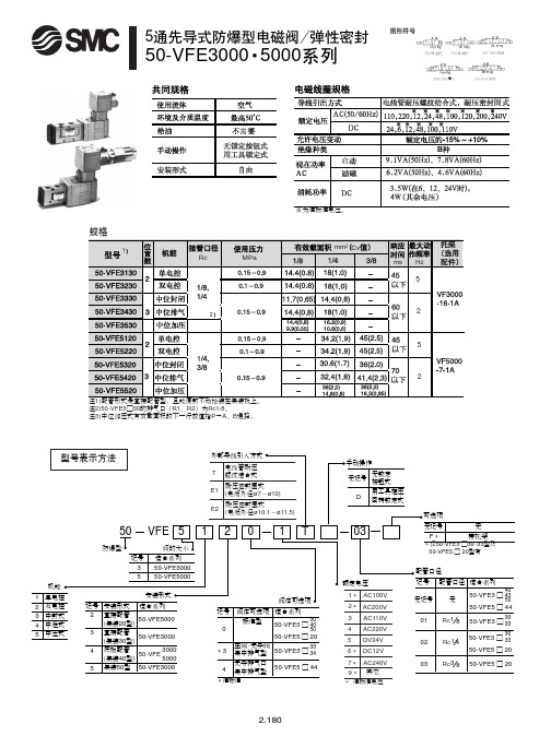
50-VFE3000 5000
泄
圈
需
启
※为准标准电压。
规格
1
mm2 Cv Rc MPa ms Hz
5
2
2
5
2
注1)配管形式是直接配管型,且能原封不动地装在集装板上。 注2)50-VFE3□30的排气口(R1、R2)为Rc1/8。 注3)中位加压式有效截面积的下一行数值指P→A、B通路。
VFE 5
阀的大小 适合系列 50-VFE3000 50-VFE5000 安装形式
1
2
0
1
T
03
无记号 F*
无 带托架
*仅50-VFE3 □30 · 33型及 50-VFE5 □ 20型有
配管口径 额定电压 阀体可选项 记号 0 阀体可选项 适合系列 30 标准型 50-VFE3 □ 40
50
记号ቤተ መጻሕፍቲ ባይዱ无记号 01 02 03
回 转 部
盖可在360°内回转 注)从外部拧入固定盖的螺钉 盖
2-Rc1/8 (R1、R2 通口)
M5 × 0.8 (PE 通口)
耐压密封圈式引入方式
50-VFE3130- □ E- □□(-F)
手动操作 (非锁式) 2-Rc 1/4、1/8 (A、 B 通口) 接线盒可转动范围 注)外部拧入固定接线盒位置的螺钉
6* DC12V 7* AC240V 9* 其它
* 准标准电压
*准标准
2.180
5
!"#$%&': 50-VFE3000 !"=E F 50-VFE3000 !"/2 !
电磁阀规格表

ZCT-6ZA ZCT-6ZA 81127300.1230 91127300.1440 2231006ET
全佳 全佳 全佳
G1/2 DN15 PN0.025-1.6MPa 220V/AC 50Hz G1/2 DN14 PN0.025-1.6MPa 220V/AC 50Hz G1/2 DN6 PN0-0.4MPa 24V/DC
SMC VCW21-4D-5-02F(品牌:SMC) 全佳 欧凯 2231006HT OK6203A-B06-C2-G1/4-D110-304 ZCT-6
G1/2 DN6 PN0-0.6MPa 220V/AC 50-60Hz B06-C2-G1/4-D110-304 DN3 0~12bar 80℃DC110V
6 7 8 9 10
全佳 自力 自力
2231015BHT
G1/2 DN10 PN0.03-1.0MPa 220V/AC 50-60Hz AC380V AC220V G1/4 G1/4 DN6 DN6 0.6MPa 0.6MPa
宁波全佳气动元件制造有限公司 上海自力电磁阀厂 上海自力电磁阀厂 宁波全佳气动元件制造有限公司 宁波全佳气动元件制造有限公司 宁波全佳气动元件制造有限公司
电磁阀规格表序号品牌规格制造商自力zct6zcsac220vg14dn6005mpa上海自力电磁阀厂2231006htg12dn6pn006mpa220vac5060hz宁波全佳气动元件制造有限公司铁路优选ok6203ab06c2g14d110304上海欧凯电磁阀制造有限公司zct6余姚市仪表四厂2231015bhtg12dn10pn00310mpa220vac5060hz宁波全佳气动元件制造有限公司船用优选自力zct6zaac380vg14dn606mpa上海自力电磁阀厂船用保温台等自力zct6zaac220vg14dn606mpa上海自力电磁阀厂811273001230g12dn15pn002516mpa220vac50hz宁波全佳气动元件制造有限公司911273001440g12dn14pn002516mpa220vac50hz宁波全佳气动元件制造有限公司112231006etg12dn6pn004mpa24vdc宁波全佳气动元件制造有限公司ksqia660df60ksqa4520df20ksqa4520adf20aksqa4520cdf20cksqa4520ddf20dvcw214d502f品牌
SMC电动阀类产品说明书
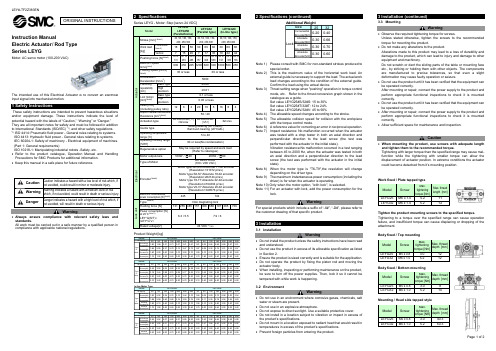
Instruction ManualElectric Actuator / Rod Type Series LEYGMotor: AC servo motor (100-200 VAC)The intended use of thisElectrical Actuator is to convert an electrical input signal into mechanical motion.1 Safety InstructionsThese safety instructions are intended to prevent hazardous situations and/or equipment damage. These instructions indicate the level of potential hazard with the labels of “Caution,” “Warning” or “Danger.” They are all important notes for safety and must be followed in addition to International Standards (ISO/IEC) *1), and other safety regulations. *1)ISO 4414: Pneumatic fluid power - General rules relating to systems. ISO 4413: Hydraulic fluid power - General rules relating to systems.IEC 60204-1: Safety of machinery - Electrical equipment of machines. (Part 1: General requirements)ISO 10218-1: Manipulating industrial robots -Safety. etc.∙ Refer to the product catalogue, Operation Manual and Handling Precautions for SMC Products for additional information. ∙ Keep this manual in a safe place for future reference.CautionCaution indicates a hazard with a low level of risk which, ifnot avoided, could result in minor or moderate injury.WarningWarning indicates a hazard with a medium level of riskwhich, if not avoided, could result in death or serious injury.DangerDanger indicates a hazard with a high level of risk which, ifnot avoided, will result in death or serious injury.Warning∙ Always ensure compliance with relevant safety laws and standards.All work must be carried out in a safe manner by a qualified person in compliance with applicable national regulations.2 SpecificationsSeries LEYG - Motor: Step [servo 24 VDC]Product Weight [kg]30501001502002503003050100150200250300Incremental E ncoder[S2] 1.80 1.99 2.31 2.73 3.07 3.41 3.67 1.81 2.02 2.26 2.69 2.95 3.27 3.51AbsoluteE ncoder[S6] 1.86 2.05 2.37 2.79 3.13 3.47 3.73 1.87 2.08 2.32 2.75 3.01 3.33 3.57AbsoluteE ncoder[T6] 1.80 2.00 2.40 2.80 3.10 3.50 3.70 1.90 2.10 2.30 2.70 3.00 3.30 3.60Absolute E ncoder[V6]1.701.902.202.603.003.303.601.701.902.202.602.903.203.4030501001502002503003050100150200250300Incremental E ncoder[S2] 3.24 3.50 4.05 4.80 5.35 5.83 6.28 3.24 3.51 3.90 4.64 5.06 5.56 5.96AbsoluteE ncoder[S6] 3.18 3.44 3.99 4.74 5.29 5.77 6.22 3.18 3.45 3.84 4.58 5.00 5.50 5.90AbsoluteE ncoder[T6] 3.20 3.40 4.00 4.70 5.30 5.70 6.20 3.20 3.40 3.80 4.60 5.00 5.50 5.90Absolute E ncoder[V6]3.103.404.004.705.305.706.203.103.403.804.505.005.505.90In-line Motor Type30501001502002503003050100150200250300IncrementalE ncoder[S2] 1.83 2.02 2.34 2.76 3.10 3.44 3.70 1.84 2.05 2.29 2.72 2.98 3.30 3.54AbsoluteE ncoder[S6] 1.89 2.08 2.40 2.82 3.16 3.50 3.76 1.90 2.11 2.35 2.78 3.04 3.36 3.60AbsoluteE ncoder[T6] 1.90 2.10 2.40 2.80 3.10 3.50 3.70 1.90 2.10 2.30 2.80 3.00 3.30 3.60Absolute E ncoder[V6]1.701.902.202.603.003.303.601.702.002.202.602.903.203.4030501001502002503003050100150200250300Incremental E ncoder[S2] 3.26 3.52 4.07 4.82 5.37 5.85 6.30 3.26 3.53 3.92 4.66 5.08 5.58 5.98AbsoluteE ncoder[S6] 3.20 3.46 4.01 4.76 5.31 5.79 6.24 3.20 3.47 3.86 4.60 5.02 5.52 5.92AbsoluteE ncoder[T6] 3.20 3.40 4.00 4.70 5.30 5.80 6.20 3.20 3.40 3.80 4.60 5.00 5.50 5.90Absolute E ncoder[V6]3.203.404.004.705.305.806.203.203.403.804.605.005.505.90Stroke[mm] TypeofMotorLEYG32M LEYG32L Stroke[mm] TypeofMotorSeriesSeriesLEYG25M LEYG25L LEYG25M LEYG25L Stroke[mm] SeriesLEYG32M LEYG32L Stroke[mm] TypeofMotorTypeofMotorSeries2 Specifications (continued)A dditional Weight2532Incremental E ncoder[S2]0.200.40Absolute E ncoder[S6]0.300.66Absolute E ncoder[T6]0.300.70Absolute E ncoder[V6]0.300.60Size LockNote 1) Please consult with SMC for non-standard strokes produced tospecial order.Note 2) This is the maximum value of the horizontal work load. Anexternal guide is necessary to support the load. The actual work load changes according to the condition of the external guide. Confirm the load using the actual device.Note 3) Thrust setting range when "pushing" operation in torque controlmode, etc. Refer to the thrust conversion graph shown in the catalogue as a guide.Set value LEYG25#S/32#S: 15 to 30% Set value LEYG25#T/32#T: 12 to 24% Set value LEYG25#V/32#V: 45 to 90%Note 4) The allowable speed changes according to the stroke.Note 5) The allowable collision speed for collision with the workpiecewith the torque control mode.Note 6) A reference value for correcting an error in reciprocal operation. Note 7) Impact resistance: No malfunction occurred when the actuatorwas tested with a drop tester in both an axial direction and perpendicular direction to the lead screw (the test was performed with the actuator in the initial state).Vibration resistance:No malfunction occurred in a test ranging between 45 to 2000 Hz, when the actuator was tested in both an axial direction and a perpendicular direction to the lead screw (the test was performed with the actuator in the initial state).Note 8) When the motor type is "T6-T9",the resolution will changedepending on the driver type.Note 9) The maximum instantaneous power consumption (including thedriver) is for when the actuator is operating.Note 10) Only when the motor option, "with lock", is selected.Note 11) For an actuator with lock, add the power consumption for thelock.WarningFor special products which include a suffix of “-X#”, “-D#”, please refer to the customer drawing of that specific product.3 Installation3.1 InstallationWarning∙ Do not install the product unless the safety instructions have been read and understood.∙ Do not use the product in excess of its allowable specification as listed in Section 2.∙ Ensure the product is sized correctly and is suitable for the application. ∙ Do not operate the product by fixing the piston rod and moving the actuator body.∙ When installing, inspecting or performing maintenance on the product, be sure to turn off the power supplies. Then, lock it so it cannot be tampered with while work is happening.3.2 EnvironmentWarning∙ Do not use in an environment where corrosive gases, chemicals, salt water or steam are present.∙ Do not use in an explosive atmosphere.∙ Do not expose to direct sunlight. Use a suitable protective cover.∙ Do not install in a location subject to vibration or impact in excess of the product’s specifications .∙ Do not mount in a location exposed to radiant heat that would result in temperatures in excess of the product’s specifications. ∙ Prevent foreign particles from entering the product.3 Installation (continued)3.3 MountingWarning∙ Observe the required tightening torque for screws.Unless stated otherwise, tighten the screws to the recommended torque for mounting the product.∙ Do not make any alterations to the product.Alterations made to this product may lead to a loss of durability and damage to the product, which can lead to injury and damage to other equipment and machinery.Do not scratch or dent the sliding parts of the table or mounting face etc., by striking or holding them with other objects. The components are manufactured to precise tolerances, so that even a slight deformation may cause faulty operation or seizure.∙ Do not use the product until it has been verified that the equipment can be operated correctly.After mounting or repair, connect the power supply to the product and perform appropriate functional inspections to check it is mounted correctly.∙ Do not use the product until it has been verified that the equipment can be operated correctly.∙ After mounting or repair, connect the power supply to the product and perform appropriate functional inspections to check it is mounted correctly.∙ Allow sufficient space for maintenance and inspection.Caution∙ When mounting the product, use screws with adequate length and tighten them to the recommended torque.Tightening with larger torque than the specified range may cause mal-function while the tightening with smaller torque can allow the displacement of actuator position. In extreme conditions the actuator could become detached from it’s mounting position.Work fixed / Plate tapped typeTighten the product mounting screws to the specified torque.Tightening to a torque over the specified range can cause operation failure, and insufficient torque can cause displacing or dropping of the attachment.Body fixed / Top mountingBody fixed / Bottom mounting Mounting / Head side tapped styleModel Screw Max.tighteningtorque [Nm]Max. thread depth [mm] LEYG25 M5 x 0.8 3.0 12LEYG32 M6 x 1.0 5.2 12 Model Screw Max.tighteningtorque [Nm]Max. thread depth [mm] LEYG25 M5 x 0.8 3.0 40.3LEYG32 M6 x 1.0 5.2 50.3ORIGINAL INSTRUCTIONSModelLEYG25 LEYG25D (Parallel/In-line )LEYG32 (Parallel type) LEYG32D (In-line type) A c t u a t o r Stroke [mm] Note1)30, 50, 100, 150, 200, 250,300 30, 50, 100, 150, 200, 250,300 30, 50, 100, 150,200, 250,300 Work load [kg] HorizontalNote 2)18 50 50 30 60 60 30 60 60 Vertical 7 15 29 7 17 35 10 22 44Pushing force [N] Note3)65 to 131 127 to 255 242 to 485 79 to 157 154 to 308 294 to 588 98 to 197 192 to 385 368 to 736Maximum Speed[mm/s]Note4)900 450 225 1200 600 300 1000 500 250 Pushing Speed [mm/s]Note5)35 or less 30 or less Acceleration / Deceleration [mm/s 2] 5000 Positioningrepeatability [mm] Basic type ±0.02 Highprecision ±0.01Lost motion [mm] Note6) Basic type 0.1 or lessHigh precision 0.05 or lessLead [mm](including pulley ratio)12 6 3 20 10 5 16 8 4 Impact resistance/vibrationResistance [m/s 2] Note7)50 / 20 Actuation type Ball screw and Belt [1:1] / Ball screw Ball screw and Belt[1.25:1] Ball screwGuide typeSliding bearing (LEYG#M), Ball bush bearing (LEYG#L) Operating temperature range [℃] 5 to 40 Operating humidity range [%RH] 90 or less(No condensation) Regenerative optionMay be required by speed and work load(Refer to catalogue)E l e c t r i c a l Motor output/size 100W /☐40 200W /☐60 Type of MotorAC servo motor (100 / 200 VAC) Encoder Note8) Motor type S2-S3:Incremntal 17-bit encoder(Resolution:131072 p/rev)Motor type S6-S7:Absolute 18-bit encoder (Resolution:262144 p/rev)Motor type T6-T7:Absolute 22-bit encoder(Resolution:4194304 p/rev) Motor type V6-V7:Absolute 20-bit encoder (Resolution:1048576 p/rev) Maximum instantaneous power consumption [W] Note9) 445 724 L o c k u n i tType Note10) Non magneting lock Holding force [N] 131 255 485 157 308 588 197 385 736 Power consumption [W] at 20 ℃ Note11) LEY*G(S/T)* /LEY*G V * 6.3 / 5.5 7.9 / 6 Rated voltage[V] 24 VDC 0-10% Model Screw Max.tighteningtorque [Nm]Max. thread depth [mm] LEYG25 M5 x 0.8 3.0 8 LEYG32 M6 x 1.0 5.2 10Model Screw Max.tighteningtorque [Nm] Max. thread length [mm]LEYG25 M6 x 1.05.2 11 LEYG32 M6 x 1.0 5.2 123 Installation (continued)3.4 LubricationCaution∙SMC products have been lubricated for life at manufacture, and do notrequire lubrication in service.∙If a lubricant is used in the system, refer to catalogue for details.∙The recommended grease is lithium grade No.2Applied Region Grease Pack Number Weight [g]Piston rodGuideGR-S-010 10GR-S-020 20∙For products which include a “25A-” prefix the recommended grease islow condensation grease.Applied Region Grease Pack Number Weight [g]Piston rodGuideGR-D-010 104 Wiring4.1 WiringWarning∙Adjustment, mounting or wiring changes should not be carried outbefore disconnecting the power supply to the product.Electric shock, malfunction and damage can result.∙Do not disassemble the cables.∙Use only specified cables.Use only specified cables otherwise there may be risk of fire anddamage.∙Do not connect or disconnect the wires, cables and connectors whenthe power is turned on.Caution∙Wire the connector correctly and securely.Check the connector for polarity and do not apply any voltage to theterminals other than those specified in the Operation Manual.∙Take appropriate measures against noise.Noise in a signal line may cause malfunction. As a countermeasureseparate the high voltage and low voltage cables, and shorten thewiring lengths, etc.∙Do not route input/output wires and cables together with power or highvoltage cables.The product can malfunction due to noise interference and surgevoltage from power and high voltage cables close to the signal line.Route the wires of the product separately from power or high voltagecables.∙Take care that actuator movement does not catch cables.∙Operate with all wires and cables secured.∙Avoid bending cables at sharp angles where they enter the product.∙Avoid twisting, folding, rotating or applying an external force to thecable.Risk of electric shock, wire breakage, contact failure and loss of controlof the product can result.∙Select “Robotic cables”in applications where cables are movingrepeatedly (encoder/ motor/ lock).Refer to the relevant operation manual for the bending life of the cable.∙Confirm correct insulation.Poor insulation of wires, cables, connectors, terminals etc. can causeinterference with other circuits. Also there is the possibility thatexcessive voltage or current may be applied to the product causingdamage.∙R efer to the auto switch references in “Best Pneumatics“ when an autoswitch is to be used4.2 Actuator Ground connectionCaution∙The Actuator must be connected to ground to shield the actuator fromelectrical noise. The screw and cable with crimping terminal andtoothed washer should be prepared separately by the user.4 Wiring (continued)4.3 Wiring of Actuator to ControllerAC servo motor driverWarningUse only specified cables otherwise there may be risk of fire and damage5 How to Order∙For standard products, refer to the catalogue on the SMC website(URL: https://) for the how to order information.6 Outline Dimensions∙For standard products, refer to the catalogue on the SMC website(URL: https://) for outline dimensions.7 Maintenance7.1 General MaintenanceCaution∙Not following proper maintenance procedures could cause the productto malfunction and lead to equipment damage.∙If handled improperly electricity and compressed air can be dangerous.∙Maintenance of electromechanical and pneumatic systems should beperformed only by qualified personnel.∙Before performing maintenance, turn off the power supply and be sureto cut off the supply pressure. Confirm that the power has beendischarged and the air is released to atmosphere.∙After installation and maintenance, apply operating pressure andpower to the equipment and perform appropriate functional andleakage tests to make sure the equipment is installed correctly.∙If any electrical or pneumatic connections are disturbed duringmaintenance, ensure they are reconnected correctly and safety checksare carried out as required to ensure continued compliance withapplicable national regulations.∙Do not make any modification to the product.∙Do not disassemble the product, unless required by installation ormaintenance instructions.∙Incorrect handling can cause an injury, damage or malfunction of theequipment and machinery, so ensure that the procedure for the task isfollowed.∙Always allow sufficient space around the product to complete anymaintenance and inspection.7 Maintenance (continued)7.2 Periodical Maintenance∙Maintenance should be performed according to the table below:AppearanceCheckBelt CheckInspection before daily operation ✓Inspection every six months* ✓✓Inspection every 1,000 km* ✓✓Inspection every 5 million cycles* ✓✓*whichever of these occurs first.∙Following any maintenance, always perform a system check. Do notuse the product if any error occurs, as safety cannot be assured ifcaused by any un-intentional malfunction.7.3 Appearance Check∙The following items should be visually monitored to ensure that theactuator remains in good condition and there are no concerns flagged;・Loose Screws,・Abnormal level of dust or dirt,・Visual flaws / faults,・Cable connections,・Abnormal noises or vibrations.7.4 Belt Check∙If one of the 6 conditions below are seen, do not continue operatingthe actuator, contact SMC immediately.・Tooth shaped canvas is worn out.Canvas fibre becomes “fuzzy”, rubber is removed, and the fibre gainsa white colour. The lines of fibre become very unclear.・Peeling off or wearing of the side of the belt.The corner of the belt becomes round and frayed, with threadsbeginning to stick out.・Belt is partially cut.Belt is partially cut. Foreign matter could be caught in the teeth andcause flaws.・Vertical line of belt teeth.Flaw which is made when the belt runs on the flange.・Rubber back of the belt is softened and sticky.・Crack on the back of the belt.8 Limitations of Use8.1 Limited warranty and disclaimer/compliance requirements∙Refer to Handling Precautions for SMC Products.9 Product disposalThis product should not be disposed of as municipal waste. Check yourlocal regulations and guidelines to dispose of this product correctly, inorder to reduce the impact on human health and the environment.10 ContactsRefer to or www.smc.eu for your local distributor /importer.URL : http// (Global) http// (Europe)'SMC Corporation, 4-14-1, Sotokanda, Chiyoda-ku, Tokyo 101-0021, JapanSpecifications are subject to change without prior notice from the manufacturer.© 2021 SMC Corporation All Rights Reserved.Template DKP50047-F-085M24VDC(5) Lock cable(4) Encoder cable(3) Motor cable(1) Electric Actuator(2) DriverHostcontroller,etc(6) I/O Connector。