弯曲力矩曲率分析,由开视.doc
材力第7章 弯曲变形分析
AC段:
1(x)
1 EI
M1(x)dx
C1
1 EI
1 16
qlx2
C1
v1(x)
1 EI
1(x)dx
D1
1 EI
1 48
qlx3
C1x
D1
CB段:
2 (x)
1 EI
M 2 (x)dx
C2
1 EI
[1 16
qlx2
1 6
q(x
l 2
)3
]
C2
v2 (x)
1 EI
2 (x)dx
D2
1 EI
[1 48
7
【例7-1】 【解】
1)先求弯矩方程
AC段 CB段
b M 1 (x) l Px, (0 x a)
M
2
(x)
b l
Px
P(xC段
1 ( x)
1 EI
M1 ( x)dx
C1
Pbx2 2EIl
C1
v1(x)
1 ( x)dx
D1
1 EI
Pb 6l
x3
C1x
D1
CB段
2 ( x)
1 EI
M 2 (x)dx
C2
P EI
[b 2l
x2
1 2
(x
a)2 ]
C2
v2 (x)
2 (x)dx
D2
P EI
[b 6l
x3
1 6
(x
a)3] C2x
D2
2020年10月17日星期六
北京邮电大学自动化学院
8
【例7-1】 【解】
3)用边界条件和连续条件确定四
个积分常数C1、D1、C2、D2 。
《弯矩曲率关系》课件

曲率的定义
曲率:描述曲线弯曲程度的量, 定义为曲线上任一点处切线方向 角的变化量与经过的弧长的比值
。
在数学上,曲率是用来衡量曲线 上某一点附近的小弧段弯曲程度
的量。
对于直线,其曲率为0;对于圆 ,其曲率是一个常数,等于圆的
半径倒数。
曲率的计算
曲率计算公式:K = lim(Δs->0) [Δs / (Δt)^2] / lim(Δt>0) [Δs / Δt]
在机械工程中的应用
传动系统设计
在机械传动系统中,弯矩曲率关系对于齿轮、轴等部件的设计和优化具有指导意义。了解弯矩与曲率的关系有助 于提高传动系统的效率和稳定性。
疲劳分析
在机械部件的疲劳分析中,弯矩曲率关系是评估其疲劳寿命的重要因素之一。通过对弯矩和曲率的变化规律进行 分析,可以预测部件的疲劳寿命和潜在的疲劳断裂风险。
在工程结构中,弯矩和曲率是密切相关的。例如,在桥梁、建筑和机械设计中,需 要考虑到结构的弯曲程度和弯矩之间的关系。
当结构受到外力作用时,会发生弯曲变形,曲率会发生变化,同时弯矩也会随之改 变。因此,在设计时需要考虑到结构的承载能力和稳定性。
了解弯矩与曲率的关系有助于工程师更好地设计结构,确保其安全性和稳定性。
需要研究弯矩曲率关系在不同温度、湿度等环境 条件下的变化规律。
需要探索弯矩曲率关系在复合材料、智能材料等 新型材料中的应用。
对学习者的建议
学习者应该深入理解弯矩和曲 率的定义及测量方法。
学习者应该掌握弹性力学和 材料力学的基本原理,以便 更好地理解弯矩曲率关系。
学习者可以通过实验和实践来 加深对弯矩曲率关系的理解和
应用。THANΒιβλιοθήκη S感谢观看详细描述
弯矩是材料力学中一个重要的概念,用于描述弯曲变形过程 中截面所受到的力矩作用。在材料受到弯曲时,截面上会产 生剪力和弯矩,弯矩的大小与剪力和中性轴距离有关。
利用弯矩-曲率(M-Φ)曲线评价截面性能

1. 点击主菜单的文件> 打开项目打开名称为‘M-Phi_Model.mcb’ 的模型文件。 2. 点击主菜单的模型> 材料和截面特性 > 截面确认已定义的两个截面
| 确认矩形截面 |
| 确认任意形状截面 |
5
03.选择材料本构模型
1. 混凝土材料本构
本例题中混凝土的材料本构使用的Kent & Park Model. Modified Kent & Park Concrete Model是 Scott etal.(1982)等在Kent & Park(1973)提出的基本模型基础上考虑横向钢筋的约束效果提出的修 正模型,模型不仅概念清楚而且能够比较准确的反映混凝土的材料特性。
复制和粘贴
| 输入钢筋 |
11
05.任意形状截面性能评价
2. 弯矩-曲率关系曲线
计算已经输入了钢筋的矩形截面的弯矩-曲率曲线。
在主菜单中选择模型 > 材料和截面特性 > 弯矩-曲率曲线 1. 勾选“显示理想模型”选项 2. 在“用户自定义曲率(理想化模型)”选项中输入‘0.002’ 3. 点击“计算”键
弯曲变形分析word版

第六章弯曲变形分析梁是机械与工程结构中最常见的构件。
本章内容包括梁的内力、平面弯曲中横截面上的正应力和切应力分布规律,以及梁的变形计算。
6.1 梁的内力●梁的概念当杆件受到矢量方向垂直于轴线的外力或外力偶作用时,其轴线将由直线变为曲线,如图6–1(a)。
以轴线变弯为主要特征的变形形式称为弯曲,凡是以弯曲变形为主的杆件,工程上称为梁,如车辆的轮轴、房屋的梁及桥梁等。
在分析计算中,通常用梁的轴线代表梁,如图6–1(b)。
图6–1 梁图6–2 对称弯曲在工程实际中,大多数梁都具有一个纵向对称面;而外力也作用在该对称面内。
在这种情况下,梁的变形对称于纵向对称面,且变形后的轴线也在对称面内,即所谓的对称弯曲,如图6–2。
它是弯曲问题中最基本、最常见的情况。
图6–3 梁的约束图6–4 三类静定梁本章只讨论梁的对称弯曲。
图6–3表示了梁的三种常见约束形式及相应的约束力:可动铰支座(图6–3(a)),固定铰支座(图6–3(b))和(平面)固定端约束(图6–3(c))。
在以上三种约束方式下,有三种常见的梁形式,如图6–4所示。
图6–4(a)为简支梁,两端分别为固定铰支座和活动铰支座;图6–4(b)为悬臂梁,一端固定端约束,一端自由;图6–4(b)为外伸梁,它是具有一个或两个外伸部分的简支梁。
这三种梁都是静定梁。
作用在梁上的外载荷,常见的有集中力偶M (图6–5(a))、分布载荷q (图6–5(b))和集中力F (图6–5(c))。
在实际问题中,q 为常数的均布载荷较为常见。
● 梁的剪力与弯矩在4.2中已经介绍了求杆件内力的通用方法,即截面法。
具体到梁,其内力分量为剪力和弯矩,规定当剪力相对于横截面的转向为顺时针为正,使杆件发生上凹下凸的弯矩为正,如图4–5(b)和(c)。
例6–1:如图6–6所示悬臂梁,受均布载荷q ,在B 点处受矩为2qa M =的力偶作用,试绘梁的剪力图与弯矩图。
解:设固定端的约束力和约束力偶为C R 和C M ,则由平衡方程00=-=∑qa R F C y ,qa R C =05.102=--⋅=∑C C M qa qa a m ,221qa M C = 以杆件左端为坐标原点,以B 为分界面,将梁分为AB 和BC 两段。
材料力学弯矩曲率关系推导
材料力学弯矩曲率关系推导一、概述在材料力学中,弯矩曲率关系是非常重要的一个概念。
它描述了杆件在受到弯曲作用时的变形情况,是理解和分析结构力学问题的基础。
本文将从基本概念入手,介绍弯矩曲率关系的推导过程,并给出实际应用案例。
二、基本概念1. 弯矩弯矩是指杆件在受到弯曲作用时所产生的内力。
通常用M表示,单位为牛米(N·m)。
2. 曲率曲率是指杆件在受到弯曲作用时所产生的变形程度。
通常用ρ表示,单位为米(m)。
3. 弯矩曲率关系弯矩和曲率之间存在着一定的关系,称为弯矩曲率关系。
它描述了当外力作用于杆件上时,杆件内部所产生的应力和变形情况。
三、推导过程1. 假设条件为了方便推导,我们假设杆件为梁形截面,并且只受到纵向载荷和垂直于截面平面方向的剪力和弯矩作用。
2. 基本方程根据材料力学的基本原理,我们可以得到以下方程:σ = M·y/I其中,σ表示截面内的应力,M表示弯矩,y表示距离中性轴的距离,I表示截面惯性矩。
3. 推导过程为了推导出弯矩曲率关系,我们需要对上述方程进行求导。
具体过程如下:dσ/dy = M/Id^2σ/dy^2 = d(M/I)/dy = -M/ I^2 · dI/dy其中,dσ/dy表示应力沿截面高度方向的变化率(即曲率),d^2σ/dy^2表示曲率沿截面高度方向的变化率(即弯矩曲率关系)。
由于I是与截面形状和尺寸有关的常数,在计算时可以视为已知量。
因此,我们可以将上式改写为:d^2σ/dy^2 = -M/ I^2 · dI/dx这就是弯矩曲率关系的基本公式。
它表明了当外力作用于杆件上时,杆件内部所产生的应力和变形情况之间存在着一定的联系。
四、实际应用1. 弯曲分析利用弯矩曲率关系,我们可以对杆件的弯曲情况进行分析。
通过计算杆件所受的弯矩和曲率,可以得出杆件内部应力和变形情况,从而判断其是否满足设计要求。
2. 结构设计在结构设计中,弯矩曲率关系也是一个非常重要的概念。
弯管力矩计算公式
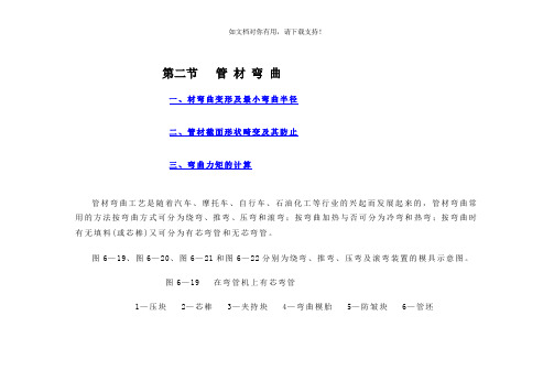
第二节管材弯曲一、材弯曲变形及最小弯曲半径二、管材截面形状畸变及其防止三、弯曲力矩的计算管材弯曲工艺是随着汽车、摩托车、自行车、石油化工等行业的兴起而发展起来的,管材弯曲常用的方法按弯曲方式可分为绕弯、推弯、压弯和滚弯;按弯曲加热与否可分为冷弯和热弯;按弯曲时有无填料(或芯棒)又可分为有芯弯管和无芯弯管。
图6—19、图6—20、图6—21和图6—22分别为绕弯、推弯、压弯及滚弯装置的模具示意图。
图6—19在弯管机上有芯弯管1—压块2—芯棒3—夹持块4—弯曲模胎5—防皱块6—管坯图6—20 型模式冷推弯管装置 图6—21 V 形管件压弯模1—压柱 2—导向套 3—管坯 4—弯曲型模 1—凸模 2—管坯 3—摆动凹模图6—22 三辊弯管原理1—轴 2、4、6—辊轮 3—主动轴 5—钢管一、材弯曲变形及最小弯曲半径管材弯曲时,变形区的外侧材料受切向拉伸而伸长,内侧材料受到切向压缩而缩短,由于切向应力θσ及应变θε沿着管材断面的分布是连续的,可设想为与板材弯曲相似,外侧的拉伸区过渡到内侧的压缩区,在其交界处存在着中性层,为简化分析和计算,通常认为中性层与管材断面的中心层重合,它在断面中的位置可用曲率半径ρ表示(图6—23)。
管材的弯曲变形程度,取决于相对弯曲半径D R 和相对厚度D t (R 为管材断面中心层曲率半径,D 为管材外径,t 为管材壁厚)的数值大小,D R 和D t 值越小,表示弯曲变形程度越大(即D R 和D t 过小),弯曲中性层的外侧管壁会产生过度变薄,甚至导致破裂;最内侧管壁将增厚,甚至失稳起皱。
同时,随着变形程度的增加,断面畸变(扁化)也愈加严重。
因此,为保证管材的成形质量,必须控制变形程度在许可的范围内。
管材弯曲的允许变形程度,称为弯曲成形极限。
管材的弯曲成形极限不仅取决于材料的力学性能及弯曲方法,而且还应考虑管件的使用要求。
对于一般用途的弯曲件,只要求管材弯曲变形区外侧断面上离中性层最远的位置所产生的最大伸长应变m ax 不致超过材料塑性所允许的极限值作为定义成形极限的条件。
弯管力矩计算公式
弯管力矩计算公式弯管力矩是指在弯曲过程中作用在弯管上的力的力矩,也可以理解为弯管的变形能力。
在工程设计和计算中,弯管力矩是非常重要的参数之一、本文将详细介绍弯管力矩的计算公式及其相关知识。
弯管力矩的计算公式可以根据不同的情况进行推导和应用。
在开始计算之前,我们需要了解一些常用的参数,包括弯管的材料特性、几何尺寸和载荷类型等。
首先,弯管的材料特性包括弯曲模量(弯管材料抵抗弯曲的能力)和弯曲应力。
弯曲模量通常由材料力学试验得出,其单位为帕斯卡(Pa),表示为E。
弯曲应力是指材料在弯曲过程中受到的应力,其单位也为帕斯卡,表示为σ。
其次,几何尺寸是指弯管本身的长度、曲率半径和壁厚等参数。
长度通常表示为L,曲率半径表示为R,壁厚表示为t。
根据以上参数,下面是一些常用的弯管力矩计算公式:1.弯管的弯曲模量(E)和弯曲应力(σ)的关系:σ=E*ε式中,ε为弯曲应变,即材料在弯曲过程中的形变程度。
2.弯管的弯曲应变(ε)和弯曲角度(θ)的关系:ε=(R/L)*θ式中,R为曲率半径,L为弯管长度,θ为弯曲角度。
3.弯管的弯曲力(M)和弯曲应力(σ)的关系:M=σ*W式中,W为弯曲截面的抵抗力矩4.弯管的弯曲截面的抵抗力矩(W)的计算公式:W=(π*D*t^2)/4式中,D为弯管的外径,t为弯管的壁厚。
需要注意的是,以上公式仅适用于一些简化的情况,如弯管为圆环形状,并且弯曲过程中没有发生塑性变形等。
在实际工程和设计中,通常会根据具体情况选择适当的公式进行计算。
弯管力矩的计算对于工程设计和结构分析至关重要。
通过合理计算和分析弯管力矩,可以确保弯管在预期工况下的安全性和可靠性。
因此,在进行弯管设计和选材时,弯管力矩的计算是不可或缺的重要一环。
工程力学中的弯曲和扭转问题的解析

工程力学中的弯曲和扭转问题的解析工程力学作为一门研究物体受力和力的效应的学科,涵盖了广泛的领域。
其中,弯曲和扭转问题是工程力学中的重要内容。
本文将就工程力学中的弯曲和扭转问题展开解析。
一、弯曲问题的解析当一个横截面直径较小,受到一个外力作用时,就会出现弯曲现象。
在工程中,我们常常需要计算和分析杆件的弯曲情况,以便设计出稳定且符合实际需求的结构。
弯曲问题的解析可以采用梁理论。
梁理论是一种基于假设的方法,即假设杆件是一维的、线弹性的,并且横截面上的应力是均匀的。
在解析弯曲问题时,首先需要确定外力作用下的弯矩分布。
然后,可以利用梁理论中的方程,例如欧拉-伯努利方程或蒙薩漢方程,来计算杆件受力、应变和位移的分布。
最后,根据梁的受力平衡条件,可以得到横截面上的剪力分布和弯曲变形的方程。
通过这些计算和分析,我们可以得出关于杆件在弯曲条件下的各种特性,例如最大弯矩、最大剪力和挠度等。
二、扭转问题的解析扭转是指杆件受到一个扭矩作用时的变形情况。
扭转问题的解析是工程中另一个重要的内容,尤其是在设计机械结构和柔性轴承时。
扭转问题的解析可以采用圆柱弹性理论。
圆柱弹性理论是一种假设杆件是圆柱形的、同轴的,并且材料满足胡克定律的理论方法。
在解析扭转问题时,首先需要确定杆件受到的扭矩分布。
然后,可以利用圆柱弹性理论中的方程,例如圆柱弹性方程和剪应力方程,来计算杆件受力和位移的分布。
最后,根据杆件的受力平衡条件和位移约束条件,可以得到关于杆件扭转情况的各种特性,例如最大剪应力、转角和扭转刚度等。
三、综合应用弯曲和扭转问题在实际工程中常常同时存在。
例如,柱子在受到向下的压力时会发生弯曲和扭转。
在这种情况下,我们需要将弯曲和扭转问题综合起来进行分析。
综合应用时,可以通过梁理论和圆柱弹性理论相结合的方法来解析问题。
首先,需要确定杆件的受力情况,包括弯矩和扭矩的分布。
然后,可以利用梁理论和圆柱弹性理论中的方程来计算杆件受力、应变和位移的分布。
- 1、下载文档前请自行甄别文档内容的完整性,平台不提供额外的编辑、内容补充、找答案等附加服务。
- 2、"仅部分预览"的文档,不可在线预览部分如存在完整性等问题,可反馈申请退款(可完整预览的文档不适用该条件!)。
- 3、如文档侵犯您的权益,请联系客服反馈,我们会尽快为您处理(人工客服工作时间:9:00-18:30)。
用OpenSees进行截面弯矩-曲率分析,分析结果可用于SAP2000自定义铰属性Moment Curvature ExampleFrom OpenSeesWikiThis next example covers the moment-curvature analysis of a rectangular reinforced concrete section. In this example a Zero Length element with the fiber discretization of the cross section is used. In addition to providing understanding as to the creation of a fiber section, the example introduces Tcl language features such as variable and command substitution, expression evaluation and the use of procedures.Here is the file: MomentCurvature.tclNOTE:1.The lines in the dashed boxes are lines that appear in theinput file.2.all lines that begin with # are comments, they are ignored bythe program (interpreter) but are useful for documenting thecode. When creating your own input scripts you are highlyencouraged to use comments.Tcl BasicsIn the tcl script that is to be presented, variables, expressions and procedures are used.A variable is a symbolic name given to some known or unknown quantity or information, for the purpose of allowing the name to be used independently of the information it represents. In Tcl a variable once set (with the set command) can then be subsequently using the syntax of $variable. The following tcl example sets the variable v to be 2.0, and then prints to the screen a message saying what the value of v is.set v 3.0puts "v equals $v"Expressions can be evaluated using the expr command. When using the expr command, most mathematical functions found in any programming language can be used, e.g. sin(), cos(), max(), min(), abs(),... It is also typical to combine an expression command, with a set command. To do this, the expr command is enclosed in square brackets []'s. The following example demonstrates the setting of a variable v to be 3.0, the setting of another variable sum to be the result of adding whatever the value of the variable v is to 2.0, and finally the printing to the screen of a message saying what the current value of sum is.Typically, the result of an expression is then set to another variable. A simple example to add 2.0 to a parameter and print the result is shown below:set v 3.0set sum [expr $v + 2.0]puts "sum equals $sum"; # print the sumMomentCurvature.tcl ScriptThe file contains 2 parts. The first part contains a procedure named MomentCurvature, and the second part contains the creation of thesection and the subsequent calling of the procedure.NOTES:1.Typically useful procedures such as MomentCurvature would beplaced in a separate file. This is done so that other scriptscan also use them. It is only placed in the same file here tolimit the number of downloads for the reader of this article.2.In the referenced file, the procedure proceeds the calling ofthe procedure. It must always be thus. In this article wediscuss the section generation first.Section DefinitionFor the zero length element, a section discretized by concrete and steel is created to represent the behaviour. UniaxialMaterial objects are created which define the fiber stress-strain relationship's. There is confined concrete in the core, unconfined concrete in the cover region, and reinforcing steel.The dimension of the section are as shown in the figure. The section depth is 24 inches, the width 15 inches, and there is 1.5inch cover all around. Strong axis bending is about the z-axis. The section is separated into confined and unconfined concrete regions, for which separate discretizations will be generated, Reinforcing steel is placed around the boundary of th confined and unconfined regions. The fiber discretization is shown below:The following are the commands that generate the section and perform the moment curvature analysis. The model and analysis commands are contained in the MomentCurvature procedure. These are contained in a seperate file which are "sourced"" by the main script.# units: kip, in# Remove existing modelwipe# Create ModelBuilder (with two-dimensions and 3 DOF/node)model BasicBuilder -ndm 2 -ndf 3# Define materials for nonlinear columns# ------------------------------------------# CONCRETE tag f'c ec0 f'cu ecu# Core concrete (confined)uniaxialMaterial Concrete01 1 -6.0 -0.004 -5.0 -0.014# Cover concrete (unconfined)uniaxialMaterial Concrete01 2 -5.0 -0.002 0.0 -0.006# STEEL# Reinforcing steelset fy 60.0; # Yield stressset E 30000.0; # Young's modulus# tag fy E0 buniaxialMaterial Steel01 3 $fy $E 0.01# ------------------------------------------# set some paramatersset colWidth 15set colDepth 24set cover 1.5set As 0.60; # area of no. 7 bars# some variables derived from the parametersset y1 [expr $colDepth/2.0]set z1 [expr $colWidth/2.0]# Define cross-section for nonlinear columnssection Fiber 1 {# Create the concrete core fiberspatch rect 1 10 1 [expr $cover-$y1] [expr $cover-$z1] [expr $y1-$cover] [expr $z1-$cover]# Create the concrete cover fibers (top, bottom, left, right)patch rect 2 10 1 [expr -$y1] [expr $z1-$cover] $y1 $z1patch rect 2 10 1 [expr -$y1] [expr -$z1] $y1 [expr $cover-$z1]patch rect 2 2 1 [expr -$y1] [expr $cover-$z1] [expr $cover-$y1] [expr $z1-$cover]patch rect 2 2 1 [expr $y1-$cover] [expr $cover-$z1] $y1 [expr $z1-$cover]# Create the reinforcing fibers (left, middle, right)layer straight 3 3 $As [expr $y1-$cover] [expr $z1-$cover] [expr $y1-$cover] [expr $cover-$z1]layer straight 3 2 $As 0.0 [expr $z1-$cover] 0.0 [expr $cover-$z1] layer straight 3 3 $As [expr $cover-$y1] [expr $z1-$cover] [expr $cover-$y1] [expr $cover-$z1]}# Estimate yield curvature# (Assuming no axial load and only top and bottom steel)set d [expr $colDepth-$cover] ;# d -- from cover to rebarset epsy [expr $fy/$E] ;# steel yield strainset Ky [expr $epsy/(0.7*$d)]# Print estimate to standard outputputs "Estimated yield curvature: $Ky"# Set axial loadset P -180set mu 15; # Target ductility for analysisset numIncr 100; # Number of analysis increments# Call the section analysis procedureMomentCurvature 1 $P [expr $Ky*$mu] $numIncrMoment Curvature ProcedureThe Tcl procedure to perform the moment-curvature analysis follows. The procedure takes as input the tag of the section to be analyzed, the axial load, P, to be applied, the max curvature to be evaluated and the number of iterations to achieve this max curavature.The procedure first creates the model which consists of two nodes, boundary conditions, and a ZeroLengthSection element. A depiction of the geometry is as shown in the top most figure above. The image on the left shows an edge view of the element, with local z-axis coming out of the page. Node 1 is completely restrained, with the applied loads acting at Node 2. An axial load, P, is applied to the section during the moment curvature analysis.After the model has been created, the analysis is performed. A single load step is first performed for the axial load, then the integrator is changed to DisplacementControl to impose nodal displacements, which map directly to section deformations. A reference moment of 1.0 is defined in a Linear time series. For this reference moment, the DisplacementControl integrator will determine the load factor needed to apply the imposed displacement. A node recorder is defined to track the momentcurvature results. The load factor is the moment, and the nodal rotation is in fact the curvature of the element with zero thickness.proc MomentCurvature {secTag axialLoad maxK {numIncr 100} } { # Define two nodes at (0,0)node 1 0.0 0.0node 2 0.0 0.0# Fix all degrees of freedom except axial and bendingfix 1 1 1 1fix 2 0 1 0# Define element# tag ndI ndJ secTagelement zeroLengthSection 1 1 2 $secTag# Create recorderrecorder Node -file section$secTag.out -time -node 2 -dof 3 disp# Define constant axial loadpattern Plain 1 "Constant" {load 2 $axialLoad 0.0 0.0}# Define analysis parametersintegrator LoadControl 0.0system SparseGeneral -piv; # Overkill, but may need the pivoting!test NormUnbalance 1.0e-9 10numberer Plainconstraints Plainalgorithm Newtonanalysis Static# Do one analysis for constant axial loadanalyze 1# Define reference momentpattern Plain 2 "Linear" {load 2 0.0 0.0 1.0}# Compute curvature incrementset dK [expr $maxK/$numIncr]# Use displacement control at node 2 for section analysisintegrator DisplacementControl 2 3 $dK# Do the section analysisanalyze $numIncr}ResultsWhen you run this script, you should see the following printed to the screen:In addition, your directory should contain the following a file section1.out. A plot of this file using the following matlab commandsload section1.outplot(section1(:,2),sections1(:,1)xlabel("Curvature 1/in")ylabel("Moment kip-in")will produce the following:。