An Audio Frequency Model of a 2×25 kV Traction Line for High Speed Railway Systems
喀呖声测试标准
喀呖声测试标准
喀呖声(Click)测试是一种用于评估电子设备音频噪声的测试方法,通常用于音频设备、耳机、扬声器等产品的质量检测。
以下是一些常见的喀呖声测试标准:
1. IEC 60268-2:这是国际电工委员会(IEC)制定的音频设备测试标准,其中包含了喀呖声测试的要求。
该标准规定了测试信号、测试条件和测试方法,以评估音频设备在不同频率范围内的喀呖声水平。
2. ANSI/CTA-2034:这是美国国家标准协会(ANSI)和消费技术协会(CTA)共同制定的标准,适用于电视、音频设备和其他消费电子产品的喀呖声测试。
该标准规定了测试信号、测试条件和测试方法,以评估设备在不同音频频率下的喀呖声水平。
3. ITU-R BS.1770:这是国际电信联盟(ITU)制定的音频质量评估标准,其中包含了喀呖声测试的要求。
该标准提供了一种客观的方法来测量和评估音频信号中的喀呖声水平。
这些标准通常涵盖了测试信号的生成、测试设备的要求、测试环境的条件以及测试结果的报告和评估方法等方面。
通过遵循这些标准进行喀呖声测试,可以确保测试结果的准确性和可重复性,有助于评估音频设备的噪声水平和质量。
具体的喀呖声测试标准可能会因产品类型、应
用领域和地区而有所差异,因此在进行喀呖声测试时,应根据适用的标准进行选择和应用。
2005-49-EC

COMMISSION DIRECTIVE2005/49/ECof25July2005amending,for the purposes of their adaptation to technical progress,Council Directive72/245/EEC relating to the radio interference(electromagnetic compatibility)of vehicles and Council Directive 70/156/EEC on the approximation of the laws of the Member States relating to the type-approval ofmotor vehicles and their trailers(Text with EEA relevance)THE COMMISSION OF THE EUROPEAN COMMUNITIES,Having regard to the Treaty establishing the European Community,Having regard to Council Directive70/156/EEC of6February 1970on the approximation of the laws of the Member States relating to the type-approval of motor vehicles and their trailers(1),and in particular Article13(2)thereof,Having regard to Council Directive72/245/EEC relating to the radio interference(electromagnetic compatibility)of vehicles(2), and in particular Article4thereof,Whereas:(1)Directive72/245/EEC is one of the separate directivesunder the type-approval procedure established byDirective70/156/EEC.(2)In order to improve safety of vehicles by encouragingdevelopment and deployment of technologies utilisingautomotive short-range radar equipment,theCommission has harmonised by Commission Decision2004/545/EC of8July2004on the harmonisation ofradio spectrum in the79GHz range for the use ofautomotive short-range radar equipment in theCommunity(3)and by Commission Decision2005/50/EC of17January2005on the harmonisationof the24GHz range radio spectrum band for the time-limited use by automotive short-range radar equipmentin the Community(4),the use of two radio spectrumfrequency bands.(3)The79GHz range radio spectrum band has been iden-tified as the most suitable band for long-term devel-opment and deployment of automotive short-rangeradar.Accordingly Decision2004/545/EC designatedand made available for automotive short-range radarequipment the79GHz range radio spectrum band ona non-interference and non-protected basis.However,thetechnology in the79GHz range radio spectrum band isstill under development and is not immediately availableon a cost-effective basis.(4)The time-limited use of the24GHz range radiospectrum band for automotive short-range radarsequipment has been permitted by Decision2005/50/EC.The technology using this frequency bandis available in the short-term at a reasonable cost,whichwill make it possible to quickly evaluate the effectivenessof the deployment of automotive short-range radarequipment as regards road safety.However,the use ofradars of that technology has to be limited to avoidinterference with other applications that use the24GHz range radio spectrum band.(5)Decision2005/50/EC permits the use of24GHz radarequipment only when originally installed in new vehiclesor when replacing one so installed and for a periodending30June2013at the latest.However,accordingto Article5of Decision2005/50/EC,that date may beadvanced.(6)In accordance with Decision2005/50/EC,Member Stateshave to set up a monitoring system aiming to quantifythe number of vehicles equipped with24GHz short-range radars equipment registered in their territory.It istherefore necessary to provide Member States with theappropriate means to carry out this monitoring.(7)Directive72/245/EEC should therefore be amendedaccordingly.(8)The amendments to Directive72/245/EEC have animpact on Directive70/156/EEC.It is thereforenecessary to amend that directive accordingly.ENL194/12Official Journal of the European Union26.7.2005(1)OJ L42,23.2.1970,p1.Directive as last amended by CommissionDirective2004/104/EC(OJ L337,13.11.2004,p.13).(2)OJ L152,6.7.1972,p.15.Directive as last amended by Directive2004/104/EC.(3)OJ L241,13.7.2004,p.66.(4)OJ L21,25.1.2005,p.15.(9)The measures provided for in this Directive are inaccordance with the opinion of the Committee for Adap-tation to Technical Progress established by Article13ofDirective70/156/EEC,HAS ADOPTED THIS DIRECTIVE:Article1Amendment to Directive72/245/EEC Directive72/245/EEC is amended as follows:1.In Annex I,the following points are inserted after point2.1.12.2:‘2.1.13.“24GHz short-range radar equipment”means a radar as defined in Article2(2)of CommissionDecision2005/50/EC(*),and satisfying theperformance requirements of Article4of thatDecision.2.1.14.“79GHz short-range radar equipment”means aradar as defined in Article2(b)of CommissionDecision2004/545/EC(**),and satisfying theperformance requirements of Article3of thatDecision.___________(*)OJ L21,25.1.2005,p.15.(**)OJ L241,13.7.2004,p.66.’2.In Annex II A,the following points are inserted after point12.2.7:‘12.7.1.vehicle equipped with a24GHz short-range radar equipment:Yes/No(strike out which is notapplicable)12.7.2.vehicle equipped with a79GHz short-range radarequipment:Yes/No(strike out which is notapplicable)’.3.In the appendix to Annex III A the following points areinserted after point1.3:‘1.3.1.vehicle equipped with a24GHz short-range radar equipment:Yes/No(strike out which is notapplicable)1.3.2.vehicle equipped with a79GHz short-range radarequipment:Yes/No(strike out which is notapplicable)’.Article2Amendment to Directive70/156/EEC Directive70/156/EEC is amended as follows.1.In Annexes I and III,the following points are inserted afterpoint12.6.4:‘12.7.1.vehicle equipped with a24GHz short-range radar equipment:Yes/No(strike out which is notapplicable)12.7.2.vehicle equipped with a79GHz short-range radarequipment:Yes/No(strike out which is notapplicable)’.2.In Annex IX on Side2of all models of the Certificate ofconformity(COC),item50is replaced by the following:‘50.Remarks50.1.vehicle equipped with a24GHz short-range radarequipment:Yes/No(strike out which is not applicable)50.2.vehicle equipped with a79GHz short-range radarequipment:Yes/No(strike out which is not applicable)50.3.Other remarks......................................................................’.Article3Transitional provisions1.With effect from1July2006,if the provisions laid down in Directive72/245/EEC,as amended by this Directive,are not fulfilled,Member States,on grounds related to electromagnetic compatibility:(a)shall consider certificates of conformity which accompanynew vehicles in accordance with the provisions of Directive 70/156/EEC to be no longer valid for the purposes of Article7(1)of that Directive;(b)may refuse the registration,sale or entry into service of newvehicles.Existing approvals for vehicles not fitted with24GHz or 79GHz short-range radar equipment remain unchanged.2.With effect from1July2013,Member States shall prohibit the registration,sale or entry into service of vehicles equipped with24GHz short-range radar equipment.EN26.7.2005Official Journal of the European Union L194/133.In case the reference date in Article2(5)of Decision 2005/50/EC is modified in accordance with Article5of that Decision,Member States shall prohibit the registration,sale or entry into service of vehicles equipped with24GHz short-range radar equipment after the modified reference date.Article4Transposition1.Member States shall adopt and publish,by30June2006 at the latest,the laws,regulations and administrative provisions necessary to comply with this Directive.They shall forthwith communicate to the Commission the text of those provisions and a correlation table between those provisions and this Directive.They shall apply those provisions from1July2006.When Member States adopt those provisions,they shall contain a reference to this Directive or be accompanied by such reference on the occasion of their official publication.Member States shall determine how such reference is to be made.2.Member States shall communicate to the Commission the texts of the main provisions of national law,which they adopt in the field governed by this Directive.Article5Entry into forceThis Directive shall enter into force on the twentieth day following that of its publication in the Official Journal of the European Union.Article6AddresseesThis Directive is addressed to the Member States.Done at Brussels,25July2005.For the CommissionGünter VERHEUGENVice-PresidentENL194/14Official Journal of the European Union26.7.2005。
Phase Angle Voltmeter 2500A 说明书

Phase Angle VoltmeterModel 2500AGraphical, Color DisplayIsolated inputs0.020º Phase Accuracy0.001° Phase ResolutionOn board reference generator80 dB harmonic rejectionWide frequency responseIEEE-488, USBDescriptionThe Model 2500A PAV replaces the very popular Model 2500. With the latest and most advanced DSP technology, this instrument provides a new level of performance and user friendliness. In addition, the 2500A PAV is considerably less expensive than other “traditional” PAVs. By keeping classic measurements, at- the-touch-of-a-button, the Model 2500A behaves more like an instrument and less a computer. The unit is extremely easy to use yet contains a host of features and performance characteristics that set it apart from all others.Specifically targeted at Synchro/Resolver and LVDT/RVDT applications this instrument makes measurements of Phase Angle, In-Phase, Quadrature, Fundamental and Total a breeze. All parameters can be displayed simultaneously on a bright color high resolution graphical display. The Model 2500A even includes a built-in oscilloscope for viewing input waveforms.Isolated inputs allow null, ratio and gain measurements of key parameters and a reference offset facilitates bridging measurements. A sensitive null meter is also included. An optional on-board reference generator has enough power to drive most LVDT/Synchro references. This feature can eliminate the need for an external reference; although the unit can be used with an external generator if so desired. The Model 2500A also includes pre-defined LVDT/RVDT functions such as (A-B)/(A+B) and (A-B)/Ref.But the 2500A PAV goes further. By using an external shunt, it can also, measure power, power factor, THD, harmonics, and can be used to calculate impedance.Typical DisplaysMultifunction DisplayIn Phase with null meterOscilloscopeSpecificationsChannels 2, galvanically isolated Measurement Total,Fundamental, In-phase,Quadrature, Ratio, Frequency andPhase plus Null MeterVoltage Input RangesResolution20mV rms to 630V rms in ½ decaderanges or Autoranging5 digits voltage,6 digits phase Phase Input Ranges 0.00º - 360º or ±180ºFrequency Range, Total 20Hz to 2MHzFrequency Range, Fundamental Modes20Hz to 100KHzDC Recorder Output: +/- 10VDC full scaleVoltage Accuracy: % of scale +% of Range/Over frequency and Voltage rangeRange 20-2K 2K-5K 5K-20K 20K-50K 50K-100K 100K-300K 300K-2M 20mV 0.06+0.05 0.09+0.10 0.09+0.10 0.3+0.20 1.5+0.50 - - 63mV 0.06+0.05 0.09+0.10 0.09+0.10 0.3+0.20 0.04+0.50 - - 200mV-20V 0.05+0.05 0.05+0.10 0.10+0.10 0.20+0.20 0.40+0.50 1.2+1.0 4.5+1.063V 0.05+0.05 0.05+0.10 0.10+0.10 0.20+0.20 0.40+0.50 1.2+1.0 - 200V-630V 0.12+0.05 0.12+0.10 0.12+0.10 0.40+0.20 1.20+0.50 - -Fundamental modes to 100KHz. Add 30µV to Total mode specs .Phase Accuracy20Hz to 2KHz ±0.02º 2kHz to 5kHz ±0.03º 5kHz to10kHz ±0.04º 10kHz to 20kHz ±0.05º 20kHz to 50kHz ±0.10º 50kHz to 100kHz ±0.20ºCommon Mode Rejection Ratio (CMRR)5Hz to 1KHz : 126dB1kHz to 5kHz: 110dB 5kHz to 32 kHz: 100dB 32kHz to 150KHz: 91dBHarmonic Rejection 80dB (even and odd) Max input 650Vrms Input impedance 1 M // 30pF (excluding. Leads) Coupling AC Nulling Sensitivity 1 µV*Accuracy can be improved significantly by using voltage tracking loop mode. Consult factory for details.Optional Signal Generator Frequency 20Hz to 20KHzAccuracy* Frequency ±0.05%; Amplitude ±5% (to 100kHz), no load Output Voltage 10mV to 115Vrms Output Current0 to 12.00V 0.5A 12.01 to 30.00V 0.2A 30.01 to 120V0.05AOptions: Orderinginformationexample: 01:SignalGenerator Model2500A with signal generator and 02: Front and Rear Inputs trigger output: Order: 2500A-01-03 03: Isolated Trigger Output‡Šƒmƒ”ƒ@ƒGƒ“ƒ^ƒvƒ‰ƒCƒY“ú–{‘•‘ã—•“X•§105-0004 “Œ‹ž“s•`‹æ•V‹´6-2-9 •Ü“cƒrƒ‹T EL 03(3437)9281 FAX 03(3437)9611 URL:www.nova-ent.co.jpE-mail:****************.jp。
使用DMR和DSDPlus入门说明书

Andrew Milluzzi, KK4LWR125 SE 16th Ave., Apt L202, Gainesville, FL 32601; *******************Getting Started withDMR and DSDPlus This simple tutorial can help get you started on digital modulation.Digital modulations are becoming quitepopular in Amateur Radio. Technologies likeDMR, D-STAR, and System Fusion havemade the technology accessible and a newplatform for experimentation. Recently therewas much buzz about the Tytera MD-380,an inexpensive digital mobile radio (DMR)handheld transceiver. Technologies suchas the RTL-SDR — software defined radiobased on the RTL chip set — have broughtsoftware defined radio to the masses.C ombining these two technologies canenable additional experimentation.Recently the Gator Amateur RadioClub, W4DFU, at the University of Floridainstalled a DMR repeater for Gainesvilleand the surrounding area. This repeater is agreat resource for students and Technicianclass operators to talk all over the worldusing UHF locally. It is easy to get startedwith DMR by just listening to typical DMRcontacts. Depending on the talk group, someare quick, others are well organized nets. One option to decode DMR is to purchase a radio. Another is constructing a receiver from an RTL-SDR, an antenna, and some software.What is DMR?DMR stands for Digital Mobile Radio. Sometimes it is called MotoTURBO, the DMR product produced by Motorola Solutions. Like D-STAR or System Fusion, DMR digitizes voice using a vocoder and sends the information via digital packet. Unlike D-STAR and System Fusion, DMR uses TDMA (Time Division Multiple Access) with two time slots in 12.5 kHz. This enables one DMR repeater to act as two on a given frequency.What is DSDPlus?DSDPlus is an application that runs on aWindows computer that can decode multipledigital modes.1 Similar to the open sourceDSD program, DSDPlus takes an audiostream from a radio and can generate text oraudio. The main difference for the scope ofthis tutorial is that the open source programmust be compiled from source code, whileDSDPlus offers a Windows binary.Hardware SetupMy decoding setup requires just a fewpieces of physical hardware, seen in Figure1, and a some virtual hardware. The firstthing you need is a DMR source. I alreadyhad purchased a Tytera MD-380 handheldtransceiver, since I am quite interested inthe ongoing firmware experimentationcommunity. Y ou might already have a DMRsource, via other hams and perhaps a localrepeater. If you do decided to purchase aDMR radio, Motorola Solutions and Hyteraeach make some outstanding radios. BothC onnect Systems and Tytera make somemore inexpensive options.The second needed piece of hardware is aradio to connect to your computer. Y ou coulduse a VHF/UHF radio and a sound card tointerface with your computer. However, Iopted for an RTL-SDR for this project. AnRTL-SDR is essentially an inexpensive TVtuner USB dongle for your computer. Itcan be purchased for less than $20 and cancover 50 MHz to 1.7 GHz. Your Windows Figure 1 — DMR decoding setup using a Tytera MD-380 handheld transceiver, a laptop computer, and an RTL-SDR dongle. [Andy Milluzzi, KK4LWR, photo]QEX March/April 2017 1920 QEX March/April 2017operating system will most likely need a special driver to use the card as an SDR. Y ou can install the correct driver with assistance from the Zadig web page.2 The Zadig website has a simple guide for installing the WinUSB driver. This tutorial will assume you are using an RTL-SDR with the appropriate driver. The final needed hardware component for this tutorial is virtual. The DSD software needs a way to pass the audio. If you are using your computer sound card and an external radio, then you can skip this hardware. I recommend a VB-Audio Virtual Cable as a free solution.3 When you download and install the software, you should notice a new audio input and output device on your computer that acts as a sound card.Setting up DSDPlus SuiteDownload the latest version of DSDPlus and DSDPlus DLL package from the DSDPlus web page.4 Extract the contents of the DSDPlus zip file and the DLL zip file to a folder. Y ou should see a few dozen files. For this tutorial, we will focus on FMP-VC.bat and VC.bat. In DSDPlus two programs must be configured: FMP and DSDPlus. FMP is a basic narrowband FM tuner for an SDR. DSDPlus is the decoder.With all the files extracted, open a command prompt. In the Windows environment, this can be done by pressing the Windows key on your keyboard and typing C MD. Once open, navigate to the folder containing the DSDPlus files. Another option in Windows 8 or Windows 10 is to click on the File menu in your Explorer window. One of the options listed is open a command prompt. If done from the DSDPlus folder, you will not need to navigate.Setting up FMPOpen the file FMP-VC.bat. Y ou will see several parameters. Modify this script for our use by configuring the four parameters “–I”, “–o”, “–P”, and “–f”. The “–i” parameter followed by number (without a space) indicates which SDR to use as an input. For the SDR we can assume it is the only one on your computer, so set it to “–i1”. The “–o” parameter followed by a number is the output audio device. The “–P” parameter is the parts-per million (ppm) correction for your SDR. The “–f” parameter is the frequency in megahertz.To determine the values for the other parameters requires some knowledge about your setup. Let’s first tackle the output audio source. Each computer is different. The best way to determine the audio output is to observe what FMP sees. For this next part, you might find it helpful to unplug theSDR from the computer; if it is plugged inFigure 3 — Screen capture of FMP successfully running, controlling the SDR. Note thecommand prompt window showing the correct ppm correction and frequency.Figure 2 — Running FMP .EXE produces this text. Note the listed audio output devices.the program will launch. Type “FMP .EXE” in your command prompt window. Without an SDR plugged in, the application should fail to launch, but will still list the audio devices. For this program, we need to feed the output to our virtual audio port input. On my computer it is “Audio output device #2” seen in Figure 2.QEX March/April 2017 21Setting the ppm correction for your SDR is specific to your device. You can experiment by leaving it at 0.0. Alternatively you can use another SDR program such as SDR# from the AIRSPY web page to find the ppm correction.5 My device required a ppm correction of +75.The last parameter to set is the frequency to monitor. I do not want to clog the larger DMR network with my testing traffic, so I generated my own signals on 446.075 MHz, one of the UHF simplex frequency. DMR is mostly on UHF in the United States. Once the system is working, you can change the frequency to a local repeater.If done correctly, your FMP-VC.bat should look like:“FMP –i1 –o2 –P75 –f446.075”.Plug in your SDR tuner and run the script. Y ou should see several windows pop up. Y our computer screen should look like Figure 3. Save the changes to FMP-VC.bat. Y ou can close FMP by pressing the ESC key.Setting up DSDPlusC onfigure the DSDPlus script with a similar process. Open the VC.bat file and observe the various parameters. The parameters that start with a “w”:“–wsl”, “–wss”, “–wel”, and “–wcl”control where the windows are launched. Y ou can set these as you like.We must configure the audio as we did before by launching DSDPlus from our opencommand prompt. Unfortunately, there isFigure 5 — A screen capture of several windows of DSDPlus while decoding.Figure 4 — Running DSDPlus lists both input and output audio devices.no way to stop the program from opening all the windows, so you might need to move the various windows out of the way to see the command prompt and get your results. On my computer I got the results shown in Figure 4.The input should be set to the virtual audio cable output. The output must be your system speakers. In my case this results in input device #1 and output device #1 respectively. This enables me to hear anyone calling. A few other parameters must be set to make DMR work. The first parameter, “–rv”, tells DSDPlus that we expect voice. DSDPlus must also be set to decode DMR/MotoTURBO, since DSDPlus can do much more than just DMR — DSDPlus documentation indicates that it decodes D-STAR, except audio. It also can also decode P25 Phase 1 and NEXEDGE.To enable DMR we need to pass the “–fr” parameter. We also need to tell DSDPlus which of the two time slots we want tomonitor. This is done via passing “–1” or “–2” after the “–fr” parameter. Those are the only required parameters to make it work. You can record what DSDPlus decodes using the “–Pwav” parameter to save the audio as a wave file. Y ou might also discover a “–v3” parameter in the sample provided by DSDPlus. This enables verbose logging and I recommend using it, especially for debugging your scripts.When you are done, you should have a VC.bat script similar to:“DSDPlus –fr –1 –rv -Pwav –i1 –o1 –v3 –wsl400.210 –wss100.200 –wel172.522 –wcl528.0 >>VC.log”.Run VC.bat along with FMP-VC.bat and you should be able to decode DMR audio.Figure 5 is a screen capture containing several windows of information from my test transmission. If you look at the “DSD+ DMR VC Channel Activity” window you can see my target was Talk Group 99. The signal came from my radio programmed with 3112746, my DMR-MARC registered radio number. “The DSD+ VC event log” also reflects this same information. The “DSD...” window shows a trace of the audio signal. The most useful information comes from the command prompt script, lower left window. Y ou can also see DSDPlus initially locked on my signal before getting regular information. This is because my simplex mode has an “always” admit criteria. If we tweak our script to use slot two, the information for my signal would look the same in the command prompt, but no audio would play. This is because DSDPlus is expecting time slot two to provide the audio. We can also see my radio ID and the talk group in this window.Test Radio SetupTesting was done on low power andsimplex. I programmed my Tytera MD-380to use the standard Talk Group 99, TimeSlot 1, and Color Code 1, as found on theAmateur Radio guide on the DMR-MARCweb page.6 I also have the channel admitcriteria set to “always” since there is nosignal with which to sync up.ResultsThe setup easily decodes my DMR testsignals from my MD-380. Figure 5, showsthat DSDPlus is successfully decodingthe incoming DMR voice packets. Thesoftware successfully identifies key packetinformation, such as talk group, device ID,and so on. The audio output is clear and easyto understand. The software saves a “.wavfile” of the audio, enabling me to mute thespeakers while testing to avoid feedback.With the setup working correctly, I haveconfigured an old computer with the RTL-SDR to act as a DMR monitor for W4DFUrepeater. I used the time slot selection ofDSD+ to limit monitoring to time slot 2 (toavoid hearing the near constant traffic onNorth America or World Wide talk groups).This lets me hear local traffic and just a fewlarger area talk groups. The W4DFU repeateris part of the K4USD network. Details fortime slots and talk groups can be found atthe K4USD web page.7 I live a few milesfrom the W4DFU repeater and the smallstock antenna that came with the RTL-SDRis easily able to pick up the repeater frommy desk.Next StepsLike many hams, I am always learningsomething new. I love the challenge ofmastering a new technology. I am far froman expert on DMR, but I am having fundiscovering the features of this digital mode.This SDR scanner project is just one way togain a better understanding of DMR whilealso enabling a way to connect with otherusers.This tutorial was just the tip of the icebergin terms of software defined radio. Whilescanning DMR with DSDPlus is nothingnew, the software can be intimidating. Wehave just scratched the surface in whatDSDPlus can do and hopefully this willencourage you to experiment with all thefeatures or get started with DMR. Most of theDSDPlus documentation is in text files withthe software. Give it a try and see what youcan come up with!Andy Milluzzi, KK4LWR, is an AmateurExtra licensed ham, first licensed in 2012. Heis president of the Gator Amateur Radio Club,W4DFU, at the University of Florida. Andyis 2012 alumnus, receiving a BS in ComputerEngineering and a BS in Software Engineering,of the Rose-Hulman Institute of Technology inTerre Haute, Indiana. He is a PhD candidateand 2013 alumnus, receiving a MS inElectrical and Computer Engineering, at theUniversity of Florida in Gainesville, Florida.Andy loves how Amateur Radio affords himthe ability to tinker and relax, while stillincorporating his passion for engineering.Notes/2zadig.akeo.ie/3vb-audio.pagesperso-orange.fr//download-2//download//media/Amateur_Radio_Guide_to_DMR_Rev_I_20150510.pdf22 QEX March/April 2017。
《高频电子技术(第2版)》电子教案 课程思政PPT 4.3 振荡器的频率和振幅稳定度

4.3 振荡器的频率和振幅稳定度
三、提高频率稳定度的主要措施
1. 减小外界因素变化的影响
将决定振荡频率的主要元件或整个振荡器置于恒温槽 采用高稳定度直流稳压电源 采用金属屏蔽罩
采用减震器 采用密封工艺减小大气压力和湿度的影响
在振荡器和负载之间加缓冲器
EXIT
高频电子线路
4.3 振荡器的频率和振幅稳定度
主要由于器件老化。
短期频率稳定度 一天之内振荡频率的相对变化量 主要由于温度、电源电压等外界因素变化
瞬时频率稳定度 秒或毫秒内振荡频率的相对变化量
由电路内部噪声或突发性干扰引起。
EXIT
高频电子线路
4.3 振荡器的频率和振幅稳定度
4.3.1 频率稳定度
一、频率稳定度的概念
中波广播电台发射机的频率稳定度为 105
三、提高频率稳定度的主要措施
1. 减小外界因素变化的影响 2. 提高谐振回路的标准性
谐振回路在外界因素变化时,保持其谐振频率不变 的能力,称为谐振回路的标准性。
回路标准性越高,频率稳定度越好。
EXIT
高频电子线路
4.3 振荡器的频率和振幅稳定度
三、提高频率稳定度的主要措施
1. 减小外界因素变化的影响
EXIT
高频电子线路
4.3 振荡器的频率和振幅稳定度
二、导致频率不稳定的因素
外因: 温度、电源电压和负载等外界因素的影响
主要利用谐振回路的相频特性实现。振荡频率 处相频特性曲线越陡,稳频效果越好。
内因: 振荡电路的稳频能力 1. 提高回路Q值;2. 使振荡频率接近回路谐振频率。
EXIT
高频电子线路
高频电子线路
4.3 振荡器的频率和振幅稳定度
Kidde K85001-0642 火警报警器说明书
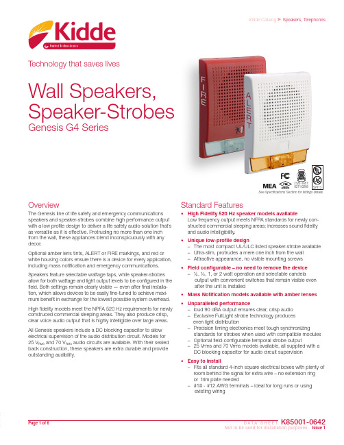
Page 1 of 6 D A T A S H E E TK85001-0642Not to be used for installation purposes. Issue 1Kidde Catalog u Speakers, TelephonesTechnology that saves livesStandard Features• High Fidelity 520 Hz speaker models availableLow frequency output meets NFPA standards for newly con-structed commercial sleeping areas; increases sound fidelity and audio intelligibility.• Unique low-profile design– The most compact UL/ULC listed speaker-strobe available – Ultra-slim, protrudes a mere one inch from the wall – Attractive appearance, no visible mounting screws • Field configurable – no need to remove the device – ¼, ½, 1, or 2 watt operation and selectable candelaoutput with convenient switches that remain visible even after the unit is installed • Mass Notification models available with amber lenses • Unparalleled performance– loud 90 dBA output ensures clear, crisp audio – Exclusive FullLight strobe technology produces even light distribution– Precision timing electronics meet tough synchronizing standards for strobes when used with compatible modules – Optional field-configurable temporal strobe output– 25 Vrms and 70 Vrms models available, all supplied with a DC blocking capacitor for audio circuit supervision • Easy to install– Fits all standard 4-inch square electrical boxes with plenty of room behind the signal for extra wire – no extension ring or trim plate needed– #18 - #12 AWG terminals – ideal for long runs or using existing wiringOverviewThe Genesis line of life safety and emergency communications speakers and speaker-strobes combine high performance output with a low profile design to deliver a life safety audio solution that’s as versatile as it is effective. Protruding no more than one inch from the wall, these appliances blend inconspicuously with any decor.Optional amber lens tints, ALERT or FIRE markings, and red or white housing colors ensure there is a device for every application, including mass notification and emergency communications. Speakers feature selectable wattage taps, while speaker-strobes allow for both wattage and light output levels to be configured in the field. Both settings remain clearly visible — even after final installa-tion, which allows devices to be easily fine-tuned to achieve maxi-mum benefit in exchange for the lowest possible system overhead.High fidelity models meet the NPFA 520 Hz requirements for newly construced commercial sleeping areas. They also produce crisp, clear voice audio output that is highly intelligible over large areas.All Genesis speakers include a DC blocking capacitor to allow electrical supervision of the audio distribution circuit. Models for 25 V RMS and 70 V RMS audio circuits are available. With their sealed back construction, these speakers are extra durable and provide outstanding audibility.Wall Speakers, Speaker-StrobesGenesis G4 Series0211/0285See Specifications Section for listings details.High Fidelity ModelsGenesis G4HF Series High Fidelity appliances provide highly intel-ligible voice audio output. They are also effective in areas subjectto high levels of ambient noise. These appliances are approved foruse in sleeping areas under conditions described below.Sleeping Room ApplicationsGenesis G4HF Series High Fidelity appliances are ideal for hotels,dormitories, and other residential occupancies where audibleoutput must meet the 520 Hz signaling characteristics required byNFPA 72.In sleeping areas, always ensure that the wattage tap of thespeaker is set sufficiently high so that the sound pressure reachesat least 75 dBA-fast at the pillow.These appliances are part of an end-to-end audio system ap-proved for use in sleeping areas when used in conjunction withapproved audio hardware and a factory-supplied 520 Hz tone.Check the System Compatibility List for other 520 Hz signalingrequirements.NOTE: Speakers driven by third-party audio systemsare not UL approved for use in sleeping rooms.Genesis mass notificationappliances bring the samehigh-performance life safetyfeatures and unobtrusivedesign to mass notificationapplications. Standard mod-els are available with clear oramber lenses and optionalALERT housing labels, theyare ideal for applicationsthat require differentiation between life safety and mass notificationalerts. Appliances with red, green or blue lenses are available.Field ConfigurationGenesis speakers may be set for ¼, ½, 1, or 2 watt operation. Thewattage setting is visible through a small window on the bottomof the device and is changed by simply sliding the switch until thedesired setting appears in the window. The speaker does not haveto be removed to change the wattage.Genesis speaker-strobes feature selectable candela output. Theoutput setting is visible through a small window on the bottom ofthe device and is changed by simply sliding the switch until thedesired setting appears in the window. The speaker-strobe doesnot have to be removed to change the output.To change strobe to temporalUse the Candela Switch and theWattage switch to set desired operation.Genesis speaker-strobes may also be configured for temporalflash. This battery-saving feature is intended for private modesignaling only. To set the device for temporal flash, snip the circuitboard as shown in the Jumper Locations diagram above.WARNING: These devices will not operate without electrical power.As fires frequently cause power interruptions, we suggest you dis-cuss further safeguards with your local fire protection specialist.Page 2 of 6D A T A S H E E T K85001-0642Not to be used for installation purposes. Issue 1Page 3 of 6 D A T A S H E E TK85001-0642Not to be used for installation purposes. Issue 1Installation and MountingAll models are intended for indoor wall mounted applications only. Speakers and speaker-strobes are flush mounted to a North-American 4” square electrical box, 21/8” (54 mm) deep or a Euro-pean 100 mm square box. Signals may be surface mounted to a Genesis surface-mount box (see ordering information for details).Two tabs at the top of the signal unlock the cover to facilitate mounting. The shallow depth of Genesis devices leaves room behind the signal for extra wiring. Once installed with the cover in place, no mounting screws are visible.Kidde recommends that these speaker-strobes always be installed in accordance with the latest recognized edition of national and lo-cal codes. Refer to installation sheet for mounting height informa-tion.WiringField wiring is connected to Genesis signals with terminals that ac-commodate #18 to #12 AWG (0.75 mm² to 2.5 mm²) wiring.Light outputPer cent of UL rating versus angle11223344556677889910112233445566778899108590Minium UL required candela light output24 Vdc 55 (65)78 (86)153 (159)196 (203)31 Vdc 45 (53)63 (69)120 (124)151 (157)20 Vfwr 56 (106)79 (147)147 (264)197 (342)24 Vfwr 50 (95)68 (130)121 (225)155 (283)27 Vfwr44 (84)60 (115)107 (200)137 (251)Light output switch settings for UL 1971 listed models are selectable by numeric candela value. Light output for Mass Notification (ECS/MNS) appliances is selectable by A, B, C, or D designations.Sound level outputUL 1480: Sound level output at 10 ft (3.05 m) measured in a reverberant room using 400 to 4,000 Hz band limited pink noise. ULC-S541: Sound level output at 10 ft (3.05 m) measured in anechoic chamber using 0 to 4,000 Hz band limited pink noise.G4 Standard Frequency ModelsUL 1480: Sound level output at 10 ft (3.05 m) measured in a reverber-ant room using 400 to 4,000 Hz band limited pink noise.1/2 Watt 83 dBA 1 Watt 86 dBA 2 Watt89 dBAAmber95 cd65 cd26 cd13 cdSpecificationsClear Strobe Output Rating UL 1971: 15 cd (fixed 15/75 cd models)UL 1638, ULCS526: 75 cd (fixed 15/75 cd models)Amber Strobe Output Rating UL 1638: 13 (D), 26 (C), 65 (B), 95 (A)Strobe Operating Voltage16 - 33 Vdc Regulated, 16-33 V Full wave rectified (UL Voltage Designations “Regulated 24” and “24 fwr”) Strobe Flash Rate One flash per second.Strobe Flash Synchronization All strobes: one flash per second (fps) within 200 milliseconds over 30 minutes on common circuit. All strobes: Synchronization source required to comply with UL 1971 synchronization standard. Temporal setting (private mode only): synchronized to temporal output on the same circuit.Synchronization Sources FACPs: VM and VS Series life safety systems, FX Series fire alarm control panels. Moduels: GSA-CC1S, GSA-MCC1S, SIGA-CC2A, GSA-MCC2A, EG1M-RM. Power supplies: MIRBPS6A, MIRBPS10A, APS6A, APS10A.Strobe Lens Material PolycarbonatePage 4 of 6D A T A S H E E T K85001-0642Not to be used for installation purposes. Issue 1Page 5 of 6 D A T A S H E E TK85001-0642Not to be used for installation purposes. Issue 1Ordering InformationLife safety Appliances G4-S2WhiteNoneNoneSpeaker only models25 Volt (Selectable ¼, ½, 1, or 2watt)1.5 lbs. (0.68 kg)G4HFWN-S2üG4R-S2 RedG4HFRN-S2üG4F-S2WhiteFIREG4HFWF-S2üG4RF-S2 Red G4HFRF-S2üEG4-S2VMWhiteNoneClearSelectable 15, 30, 75, or 110 cdG4HFWN-S2VMC üEG4R-S2VMRedG4HFRN-S2VMC üEG4F-S2VMWhiteFIREG4HFWF-S2VMC üEG4RF-S2VM Red G4HFRF-S2VMC üG4-S7WhiteNoneNoneSpeaker only models70 V (Selectable ¼, ½, 1, or 2watt)G4HFWN-S7üG4R-S7RedG4HFRN-S7üG4F-S7WhiteFIREG4HFWF-S7üG4RF-S7Red G4HFRF-S7üEG4-S7VMWhiteNoneClearSelectable 15, 30, 75, or 110 cdG4HFWN-S7VMC üEG4R-S7VMRed G4HFRN-S7VMC üEG4F-S7VMWhite FIRE G4HFWF-S7VMC üG4HFRF-S7VMC üRed EG4F-S7V1575White FIREClear15/75 cd¹EG4RF-S7V1575RedMass Notification Appliances G4WA-S2VMA*WhiteALERTAmberSelectable 13, 26, 65, or 95 cd 25 Volt (Selectable ¼, ½, 1, or 2watt)1.5 lbs. (0.68 kg)G4HFWA-S2VMA*üG4WA-S2VMC ClearSelectable15, 30, 75, or 110 cd G4HFWA-S2VMC üG4WN-S2VMA*NoneAmber Selectable 13, 26, 65, or 95 cd G4HFWN-S2VMA*üG4WN-S2VMC Clear15, 30, 75, or 110 cdG4WA-S2ALERT NoneSpeaker only models G4HFWA-S2üG4WN-S2NoneG4WA-S7VMA*WhiteALERTAmberSelectable 13, 26, 65, or 95 cd 70 V (Selectable ¼, ½, 1, or 2watt)G4HFWA-S7VMA*üG4WA-S7VMC ClearSelectable15, 30, 75, or 110 cd G4HFWA-S7VMC üG4WN-S7VMA*NoneAmber Selectable 13, 26, 65, or 95 cd G4HFWN-S7VMA*üG4WN-S7VMC Clear15, 30, 75, or 110 cdG4WA-S7ALERT None Speaker only modelsG4HFWA-S7üG4WN-S7None* Not approved for fire alarm applicationsTechnology that saves livesContact us...Email:*****************.comWeb: /EngineeredSystems Kidde is a UTC brand.1016 Corporate Park DriveMebane, NC 27302© 2016 United Technologies Corporation. All rights reserved.AccessoriesEG1M-RM Synchronization Output Module (1-gang)0.2 (0.1) GSA-CC1S Intelligent Synchronization Output Module (2-gang)0.5 (0.23) GSA-MCC1S Synchronization Output Module (Plug-in UIO)0.18 (0.08) EG4B Surface mount box, white0.7 (0.32) EG4RB Surface mount box, red0.7 (0.32)Page 6 of 6D A T A S H E E T K85001-0642Not to be used for installation purposes. Issue 110-11-16。
AM6200 95高功率中高频扬声器系统说明书
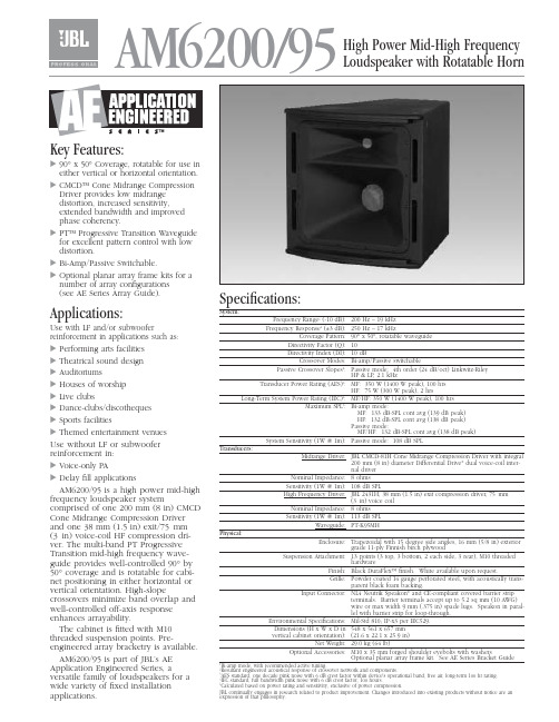
AM6200/95High Power Mid-High Frequency Loudspeaker with Rotatable HornKey Features:᭤90°x 50°Coverage, rotatable for use in either vertical or horizontal orientation. ᭤CMCD™ Cone Midrange Compression Driver provides low midrange distortion, increased sensitivity,extended bandwidth and improved phase coherency.᭤PT™ Progressive Transition Waveguide for excellent pattern control with low distortion.᭤Bi-Amp/Passive Switchable.᭤Optional planar array frame kits for a number of array configurations (see AE Series Array Guide).Applications:Use with LF and/or subwooferreinforcement in applications such as:᭤Performing arts facilities ᭤Theatrical sound design ᭤Auditoriums᭤Houses of worship ᭤Live clubs᭤Dance-clubs/discotheques ᭤Sports facilities᭤Themed entertainment venues Use without LF or subwoofer reinforcement in:᭤Voice-only PA᭤Delay fill applicationsAM6200/95 is a high power mid-high frequency loudspeaker systemcomprised of one 200 mm (8 in) CMCD Cone Midrange Compression Driver and one 38 mm (1.5 in) exit/75mm (3in) voice-coil HF compression dri-ver. The multi-band PT Progressive Transition mid-high frequency wave-guide provides well-controlled 90°by 50°coverage and is rotatable for cabi-net positioning in either horizontal or vertical orientation. High-slopecrossovers minimize band overlap and well-controlled off-axis response enhances arrayability.The cabinet is fitted with M10threaded suspension points. Pre-engineered array bracketry is available.AM6200/95 is part of JBL’s AE Application Engineered Series, aversatile family of loudspeakers for a wide variety of fixed installation applications.Specifications:System:Frequency Range 1(-10 dB):200 Hz – 19 kHz Frequency Response 1(±3 dB):250 Hz – 17 kHzCoverage Pattern:90°x 50°, rotatable waveguide Directivity Factor (Q):10Directivity Index (DI):10 dBCrossover Modes:Bi-amp/Passive switchablePassive Crossover Slopes 2:Passive mode: 4th order (24 dB/oct) Linkwitz-Riley HP & LP, 2.1 kHzTransducer Power Rating (AES)3:MF: 350 W (1400 W peak), 100 hrs HF: 75 W (300 W peak), 2 hrsLong-Term System Power Rating (IEC)4:MF/HF: 350 W (1400 W peak), 100 hrs Maximum SPL 5:Bi-amp mode:MF: 133 dB-SPL cont avg (139 dB peak)HF: 132 dB-SPL cont avg (138 dB peak)Passive mode:MF/HF: 132 dB-SPL cont avg (138 dB peak)System Sensitivity (1W @ 1m):Passive mode: 108 dB SPLTransducers:Midrange Driver:JBL CMCD-81H Cone Midrange Compression Driver with integral200 mm (8 in) diameter Differential Drive ®dual voice-coil inter-nal driverNominal Impedance:8 ohms Sensitivity (1W @ 1m):108 dB SPLHigh Frequency Driver:JBL 2431H, 38 mm (1.5 in) exit compression driver, 75mm(3in) voice coilNominal Impedance:8 ohms Sensitivity (1W @ 1m):113 dB SPLWaveguide:PT-K95MHPhysical:Enclosure:Trapezoidal with 15 degree side angles, 16 mm (5/8 in) exteriorgrade 11-ply Finnish birch plywoodSuspension Attachment:13 points (3 top, 3 bottom, 2 each side, 3 rear), M10 threadedhardwareFinish:Black DuraFlex™ finish. White available upon request.Grille:Powder coated 14 gauge perforated steel, with acoustically trans-parent black foam backing.Input Connector:NL4 Neutrik Speakon ®and CE-compliant covered barrier stripterminals. Barrier terminals accept up to 5.2 sq mm (10 AWG)wire or max width 9 mm (.375 in) spade lugs. Speakon in paral-lel with barrier strip for loop-through.Environmental Specifications:Mil-Std 810; IP-x3 per IEC529.Dimensions (H x W x D in 548 x 561 x 657 mm vertical cabinet orientation):(21.6 x 22.1 x 25.9 in)Net Weight:29.0 kg (64 lb)Optional Accessories: M10 x 35 mm forged shoulder eyebolts with washersOptional planar array frame kit. See AE Series Bracket GuideBi-amp mode, with recommended active tuning.Resultant engineered acoustical response of crossover network and components. AES standard, one decade pink noise with 6 dB crest factor within device's operational band, free air, long-term 100 hr rating.IEC standard, full bandwidth pink noise with 6 dB crest factor, 100 hours.Calculated based on power rating and sensitivity, exclusive of power compression.JBL continually engages in research related to product improvement. Changes introduced into existing products without notice are anexpression of that philosophy.᭤AM6200/95 High Power Mid-High Frequency Loudspeaker with Rotatable HornHorizontal 1/3 Octave PolarsSS AM6200/95CRP 5M 10/04᭤AM6200/95 High Power Mid-High Frequency Loudspeaker with Rotatable HornVertical 1/3 Octave PolarsJBL Professional8500 Balboa Boulevard, P.O. Box 2200Northridge, California 91329 U.S.A.©Copyright 2002 JBL ProfessionalAHarman International Company。
ROTEC 齿轮轮速度传感器说明书

The ROTEC sensors described here are designed for non-contact measurement of the rotational speed of a toothed wheel. Each sensor consists of two magnetoresistive elements and a permanent magnet enclosed in a stainless steel cylindrical housing with M10x1 outer thread. The sensor itself is entirely passive. For operation it requires an accompanying electronic unit which converts its analogue output to a TTL signal. The sensor ex-hibits minimal temperature dependence and its operation is not impaired by dirt or oil fi lms. The output signal amplitude is independent of the rotational speed. A variety of lengths and designs is available.TECHNICAL SPECIFICATIONS• Gearwheel frequency from ROTEC-sensors: 0,1 Hzup to 20 kHz• Frequency of the DSA: < 70 kHz • ferromagnetic target wheel module 0.6 to 2.4 pitch 1.9 mm to 7.7 mm • sensing gap: 0 to 5 mm• temperature range: -15°C to + 80°C(for high temperature sensors up to + 120°C)• min. sensitivity of DSA: 5 mV• max. input-voltage DSA: 10 VThe sensor‘s stainless steel cylindrical housing has an M10x1 outer thread. The target wheel should have a gear module in the range 0.6 to 2.4 mm, a pitch be-tween 1.9 and 7.7 mm and a thickness of at least 5 mm. A sensing gap from sensor to wheel of up to 5 mm is allowed for. Di erential magnetoresistive sen-sors need to be carefully positioned for both optimal adjustment of orientation w.r.t. the target wheel and setting of sensing distance.It is recommended to use the DSA only with ROTEC-sensors.When it is technically neccesary to use non-ROTEC-sensors, please be sure that the sensor’s output volt-age must not exceed the limitation of -10 V to +10 V, as this will cause unplausible signals at the analog scope-output and may damage the device.MEASUREMENT PRINCIPLE:rotecSPEED SENSORSMEASUREMENTSYSTEMSStandard Speed SensorsSensor Type A Sensor Type C Di erential Sensor Adapter Sensor Type BCable for Sensor Type B and CHigh temperature versionsrotecSPEED SENSORSMEASUREMENTSYSTEMS。
- 1、下载文档前请自行甄别文档内容的完整性,平台不提供额外的编辑、内容补充、找答案等附加服务。
- 2、"仅部分预览"的文档,不可在线预览部分如存在完整性等问题,可反馈申请退款(可完整预览的文档不适用该条件!)。
- 3、如文档侵犯您的权益,请联系客服反馈,我们会尽快为您处理(人工客服工作时间:9:00-18:30)。
An Audio Frequency Model of a 2x25 kV Traction Line for High Speed Railway SystemsRICHARD BARTONI Railway EngineerC orso Itali a, 8 300100 RomeITALYREGINA LAMEDICAFull ProfessorMARIA CARMEN FALVOPhD StudentDepartment of Electrical EngineeringUniversity of Rome La SapienzaVia Eudossiana, 1800184 RomeITALYEUGENIO FEDELIRFI Technical ManagerVia M arsala, 900100 RomeITALYAbstract: - The new Italian high-speed railway lines are characterised by a 2x25 kV – 50 Hz electrification standard. Train operation is carried out by the innovative ERTMS level II signalling system that is supported by audio frequency track circuits (AF-TC). The choice of the audio frequency is due to the necessity of eliminating the interference problems between 50 Hz traction currents and track circuit operation.The paper illustrates the audio frequency models, implemented in Alternative Transient Program (ATP), of both the electrification system and the track circuits. Interferences between traction harmonic currents and track circuit operation, compromising the system availability degree and the transportation regularity, are here analysed. The main results, concerning system resonance frequencies and rail current distribution, are presented and discussed.Key-Words: High Speed Railway Lines, Track Circuits, Audio Frequency, Harmonic Currents, Resonance Frequency1IntroductionThe new Italian high-speed railway lines are characterised by a typical 2x25 kV – 50Hz electrification system [1]. In this context train operation is carried out by the innovative ERTMS level II signalling system that is supported by audio frequency track circuits (AF-TC). This choice avoids any possible interference between 50 Hz traction currents and track circuit operation. In spite of that, interferences are possible because of the harmonic currents that are injected in the line by the motor drive equipment. This element is not anyway sufficient to determine an improper operation of the track circuit that is exclusively possible in the case that rail currents in the audio frequency model; section 4 summarizes the simulation results. Finally section 5 shows the conclusions.2System DescriptionAs far as line electrification is concerned, the Italian high speed railway network adopts a typical 2x25 kV –50 Hz configuration, as shown in figure 1, that includes HV/55 kV double secondary transformers, 55/27,5 kV autotransformers, contact wire (CW), messenger (M), feeders (FD), rail return wires (RW) and ground wirestrack circuit operational bands are unbalanced and amplified.In this case track circuits can be affected by unexpected occupations that may compromise the system availability degree and the transportation regularity. In the light of that, an analysis of both the resonance frequencies and the rail current distribution turns out quite useful and important.Alternative Transient Program (ATP) models have been then implemented with the aim to analyse the audio frequency behaviour of the electrification system [2]. In the paper section 2 reports the system description; section 3 includes the explanation of theThe characteristic geometrical disposition of anembankment/cutting line section is illustrated in figure 2; similar configurations are valid for viaduct line sections and tunnel sections where differences regard basically the position of feeders, returns wires (RW) simulate the audio frequency behaviour of the real system.Two models have been studied. The former (Model 1), representing both the electrification system and the track circuits [5], is based on 10-meter multipoles while frequency track circuits (AF-TC) of which the layout isA lumped parameter model, assuming the overall resistance is concentrated every L meters of line, represents rail-to-ground leakage. A value of 0.025 S/km has been in particular chosen for rail leakage conductance. As far as ballast, its conductivity does obviously vary with both the maintenance activities and the weather conditions.The ATP rail model (referred to a UNI 60 track section) has been moreover artificially modified in order to take into account the results of laboratory tests and to give consequently a more realistic representation of the inner resistance and inductance [6]-[7]. A similar model has been assumed for the ground wire.As far as track circuit model is concerned, coupling units and track loops are represented by Thevenin Main trackside components of the AF-TC are track coupling units, capacitive compensators, and S joints (track loops). Track coupling units interface track signals with receiver and transmitter circuits, and provide for tuning to the track circuit carrier frequency. S joints carry out the signal separation between adjacent track circuits.3 Audio Frequency Electrical ModelAlternative Transient Program (ATP), implementing the Carson Pollaczek theory, has been used in order toequivalent circuit in transmission and by specific impedance in reception.The capacitive compensators are placed every 100 m while the impedance bonds (see figure 5) are placedIn order to complete the traction line model, an equivalent circuit of the HV/55 kV - 50 Hz powertransformer has been represented in ATP as in figure 6.A similar model is implemented for the 55/27,5 kVFig.8 – Magnitude and Phase of Thevenin Impedance -Frequency in Model 1 for Train at km 16Fig.9 - Thevenin Impedance – Frequency – Train PositionFinally figure 7 reports the AF train model: the audiofrequency train operation has been represented by aharmonic current generator (10 A) with frequenciesfrom 1.9 kHz to 17.0 kHz. An ideal 1:1 transformer hasbeen introduced between the current generator and thecontact line in order to overcome an ATPimplementation limit. The model has been applied toeach specific operational frequency in the range 1.9in Model 2A comparison between these results shows a substantialmatch of both the resonance frequencies and therelevant impedances. The differences in the values offigures 8 and 9 are essentially due to a differentfrequency sampling (500 Hz for Model 1 and 100 Hzfor Model 2). It is then possible and convenient toadopt the simplified Model 2, not including therepresentation of the track circuits, in order to detectand analyse the resonance frequencies and the currentdistribution.4.2 Resonance Frequency AnalysisFigures 10 and 11 illustrate the impedance values as afunction of the frequency and the kilometric point, fortwo specific line sections:4Results4.1Comparison between the modelsThe results of the application of the two above-described models are illustrated in figures 8 and 9. Fig.10 – Impedance – Frequency - Train Positionfor Embankment/Cutting Line SectionFig.11 – Impedance – Frequency - Train Positionfor natural tunnel line sectionThese figures show the existence of different resonance frequencies. In particular it is possible to discern a substantial decrease in the resonance impedance peak values as the frequency increases. It can be justified by the increase in the line conductor resistance caused by the skin effect.It is moreover worthwhile noting that the first parallel resonance frequency of the natural tunnel line section (around 1700 Hz) is out of the first frequency band(190042300 Hz). Fig.13 – Impedance Magnitudeand PhaseThe analysis of the frequency spectra of the different line section typologies shows similar profiles and substantially equivalent impedance values. Somedifferences can however be detected around the parallel resonance frequencies.Figure 12 illustrates the superimposition between the track circuit operational frequencies and the simulation results obtained for a typical embankment/cutting line section with train at km 20.Fig.12 – Comparison between FrequenciesThe first parallel resonance frequency for this configuration (train at km 20) is within the range1800⎪2000 Hz that overlaps with the first track circuit band (190042300 Hz). Moreover the first harmonic band of the motor units is around 2000 Hz. For all these reasons this situation can be quite critical.As the frequency increases above the first parallel resonance, the impedance shows a capacitive behaviour till the amplitude reaches a minimum valuecorresponding to a series resonance that is a resonance between longitudinal and transversal line parameters. The last detected parallel resonance frequency is around 15300 Hz that is within the frequency band 15300⎪15700 Hz of the track circuits.Impedance magnitude and phase at 1950 Hz are shown in figure 13 as a function of train position.at 1950 Hz - Train PositionThe magnitude increases with the train distance from the substation while impedance phase doesn ’t vary. It means that the first resonance frequency does not depend on the train position. This result matches with the evidences of studies on similar railway lines [8]-[9]. Figure 14 shows the impedance magnitude and phase at 12500 Hz.Fig.14 - Impedance Magnitude and Phaseat 12500 Hz - Train PositionTheir profiles are symmetrical with respect to the electric section centre, at km 12. The inversion of the phase sign as train position varies, means that the resonance frequency oscillates around 12500 Hz. The particular profile of the impedance magnitude can be explained by the consideration that, for this specific frequency, each half section corresponds to half a wavelength.This behaviour is even shown by simulations that do not include transformers and autotransformers. Figure 15 shows the disappearance of the resonance frequencies other than 12500 Hz, meaning theirdependence from the discontinuities introduced by the electrical transformer.The resonance behaviour around 6250 Hz is justifiedby the /2 operation of the overall line section.Fig.17 – Rail Currents in the First Track at 1950 HzFig. 15 - Impedance Magnitude - Frequency with Transformers and Autotransformers DisconnectedThe last detected parallel resonance frequency is around 15300 Hz. At this frequency the phase curve, reported in figure 16, shows that the resonance frequency is mildly dependent on the train position. It is however worthwhile noting that traction harmonic current amplitude is not high in this frequency range.Fig.16 - Impedance Magnitude and Phaseat 15300 Hz - Train Position4.3 Current Distribution AnalysisCurrent unbalance in the rails can cause problems with track circuit operation and it is then considered a disturbance estimation parameter.The analysis of an embankment/cutting line section is hereby illustrated; the results can be anyway extended to the other line sections. The simulations have shown a significant unbalance around the parallel resonance frequencies.The first studied frequency is 1950 Hz. A 10A current generator, simulating the train, has been placed at km 20 on the first track. For this case figure 17 shows the rail currents in the first track. Similar values have been calculated for the second track. The current unbalance increases as the distance from the substation decreases. This phenomenon can be considered an effect of both the current induction and the line geometrical dissymmetry.Some discontinuities can be detected every 1500 meters that is where the impedance bonds are connected. A more consistent gap near the centre of the electric line section is caused by the autotransformer operation.A comparison can be made with the results obtained for a non-resonant frequency, at 4150 Hz for example. In this case figures 18 and 19 show an irrelevant current unbalance (about 1%) and a significant attenuation of the current magnitude.Fig. 18 - Rail Currents in the First Track – 4150 HzFig. 19 – Rail Currents in the Second Track - 4150 Hz5 ConclusionsReferences:[1] Lucio Mayer, Impianti Ferroviari, CIFI, Roma The present study has concerned the detection of an[2] [3] ATP User Guide Council Directive 96/48/EC - 23 July 1996 on The audio frequency model of the electrification system of a 2x25 kV high-speed railway line. The objective was to analyse the interference problems between the traction loads and the audiofrequency track circuits supporting the innovative ERTMS level II signalling system. The model allows estimating system resonance frequencies that can be compared with motor unit interoperability of the trans-European high-speed rail system , Official Journal L 235 , 17/09/1996[4] Commission Decision 2002/731/EC 30 May 2002 on The technical specification for interoperability relating to the control-command and signalling subsystem of the trans- European high-speed rail system , Official Journal L 245, 12/9/2002 harmonic spectra and track circuit operational[5] M.C. Falvo, E. Fedeli, R. Lamedica, A simulation frequency bands. Rail current distribution has been moreover studied by model implementation in order to detect possible problems in the track circuit operation. Results have shown a substantial independence ofsystem resonance frequencies from both the line section model of audio-frequency track circuits, Proceedings SPRTS Conference , October 2005[6] A. Mariscotti, P. Pozzobon, Measurement of the Internal Impedance of Traction Rails at Audiofrequency, IEEE Transaction on Instrumentation and Measurement, Vol. 53, n. 3, June 2004 typology and the train position. Simulations have [7] A. Mariscotti, Distribution of the Traction Return moreover shown an evident rail current unbalance around the system resonance frequencies.Next steps will regard the validation of the audio frequency model by a test campaign.AcknowledgementsThis work was supported by RFI (Rete Ferroviaria Italiana) in the frame of a Research Project of the Department of Electrical Engineering in University of Rome La Sapienza (January-June 2005)Current in AC and DC Electric Railways Systems, IEEE Transaction on Instrumentation and Measurement , Vol. 18 n. 4, October 2003[8] N. Ciaccio, R. Lamedica, A. Prudenzi, P. Verde,Harmonic resonances in railway systems electrified at 2x25 kV – 50 Hz, Proceedings 7th IEEE Conference on Harmonics and Quality of Power, (ICHQP VII), 2000[9] P. Cesario, G. Sciutto, C. Rossi, B. Mellit, Digital simulation of oscillatory overvoltage problems in AC railroad electrification, Proceedings IEE InternationalConference on Main Line Railway Electrification , September 1989, pp. 356-362。