Kopie von 10_01_Mold_delivery_checklist
Ipex+2010的印后加工

自2006年4月上届I p e x展会以来,印后加工领域已发生了显著的变化。
印刷者需求的改变,以及近两年的经济危机,都给印后加工带来很大的影响。
印刷方面最大的发展是数字印刷量的巨大增长。
传统胶印量在不断下跌,而数字印刷特别是彩色数字印刷量显著增长。
如今,数字印刷的质量已经远远高于上届I p e x 展会时的水平,施乐i G e n4,惠普Indigo,柯达Nexpress和奥西这些高速数字印刷机所生产的数字印刷品,不但质量可以与胶印相媲美,而且承印物的范围比胶印更加广泛。
对印后设备供应商来说,这些新的客户需求意味着对设备产生了新的要求。
过去的几年中,大家普遍感觉到印后设备的自动化程度和作业准备速度都提高了。
Friedheim公司是Hunkeler、施耐德、MBO及沃伦贝格设备的英国总代理,其总经理Peter Morris认为,自动化程度和作业准备速度的提高并不能满足未来的需求。
他说:“由于越来越多的印件转向按需印刷和按需装订,将对自动化印后装订设备的速度提出更高的要求,也将有更多的传统印刷品装订设备用于数字印刷品的装订。
另外,我们将看到更多的多功能装订设备出现在市场上,这些设备多以单机操作为主,不再连接到流水线当中。
如果厂家配备了一台上千万元的高档数字印刷机,不可能不投资相应的装订设备使自己的生产能力更完备。
”这种观点为很多业内人士所赞同。
海德堡英国公司印后市场经理Mark Hogan说:“经济不景气时,很多印刷加工厂都尽可能将印件在本工厂内完成而减少外发。
印后Duplo DCMBO公司M7多功能自动折页机PRINTING FIELD 2010.04加工厂如果想在这种环境中存活下来,必须装备自己以提供印刷厂所不能提供的专业印后加工服务。
”英国专业覆膜设备生产商A u-t o b o n d近两年的快速发展,正好印证了H o g a n先生的说法。
此前,Autobond覆膜机多销售给专业印后加工厂,而近两年来印刷厂的采购数量大幅增长。
Desigo PX Automation stations modular series PXC..

CM1N9222en_192022-05-11Smart Infrastructures92229222P 01Desigo™ PXAutomation stations modular seriesPXC....D PXC...-E.D PXA40-…∙Freely programmable modular automation stations for HVAC and building services plants.∙Communications – BACnet/IP– BACnet/LonTalk∙BTL label (BACnet communications is BTL tested)∙Comprehensive management and system functions (alarm management,time schedules, trends, access protection, etc.)∙Connection of TX-I/O modules with any data point mix∙Connection of TX Open modules for the integration of third-party devices ∙Integration of L ON M ARK ®-compatible devices ∙Integrated web server for generic operation∙For stand-alone applications, or for use within a device or system network ∙Scalable range of touch panels and local and remote operating devicesValidityThis data sheet is valid for firmware Desigo V6.1 and higher.For older devices / firmware see data sheet CM1N9222en_13.FunctionsModular, freely programmable automation stations for HVAC and building controlsystems.∙Management functions (alarm management with alarm routing, schedulers,trend functions, remote management, access protection with individually defineduser profiles and categories).∙For stand-alone applications or for use within a device or system network.∙BTL-tested BACnet communications on LonTalk, PTP or IP, compliant withBACnet standard (Rev. 1.12 -for Desigo V6.0 and later) including B-BC profile.∙AMEV profiles AS-A and AS-B to recommendation "BACnet 2011 - Version 1.2(for Desigo V6.0 and later)".∙Freely programmable, using the D-MAP programming language (closeresemblance to CEN standard 11312). All function blocks, available in libraries,can be graphically connected.∙Engineering and commissioning using the Desigo Xworks Plus tool.∙Connection of field devices to a customized mix of TX-I/O modules.∙Connection of installed PTM-I/O modules – the perfect solution to migrate legacysystems.∙Connection of TX Open modules to integrate third-party devices such asvariable speed drives, pumps or energy counters.∙Connection of detached I/O islands with integration.∙Connection of LonMark® compatible devices∙Low voltage protection and start-up management to protect the devices againstfluctuating voltage.∙Scalable range of touch panels, Web solutions and operator units.Modular automation station with connected TX-I/O modulesOverview of automation stations – modular seriesConnection of TX-I/O modules, TX Open modules, PTM-I/O modules via PXX-PBUS and LonWorks devices via PXX-L11/12.Activation of generic Web operation with PXA40-W1BACnet/IP PXC00-E.D PXC50-E.D PXC100-E.D PXC200-E.DBACnet/LonTalk PXC00.D PXC50.D PXC100.D PXC200.DNumber of physical data–80200350points TX-I/ONumber of TX Open–555Modules for e.g. Modbus,M-BusNumber of data points–4006001000(TX-I/O and TX Open)Number LonWorks60 or 120 1060 or 1201)60 or 1201)Devices via PXX-Lx1)In concurrent use with TX-I/O modules, the number of devices is reduced inrelation to capacityExtension capabilities of the automation stationsTXM1.. : The flexible range of TX-I/O modules for signaling, measuring,counting, switching, and positioning. The I/O modules with local manual control on the module housing permit the operator to control the equipment manually directly from the cabinet.TX-I/O devices 1)TypeData sheet Digital input module 8 or 16 I/O points TXM1.8D,TXM1.16D CM2N8172Universal module without / with local operation and LCDTXM1.8U,TXM1.8U-ML CM2N8173Super universal mod. without / with local operation and LCD TXM1.8X,TXM1.8X-ML CM2N8174Relay module without / with local operationTXM1.6R,TXM1.6R-M CM2N8175Resistance measuring module (for Pt100 4-wire)TXM1.8P CM2N8176Relay module bistable TXM1.6RL CM2N8177Triac moduleTXM1.8T CM2N8179Power supply module 1.2 A, Fused 10A TXS1.12F10CM2N8183Bus interface module,Fused 10ATXS1.EF10CM2N81831)TXM1... und TX Open modules require TXS1.12F10power supply modules.TX Open : Flexible TX Open platform to integrate third-party systems anddevices such as Modbus or M-Bus. Tested integrations solutions and appli-cations based on our large know how.TX Open devices 1)TypeData sheet TX Open module up to 40 data points TXI2-S.OPEN CM1N8187TX Open moduleup to 160 data pointsTXI2.OPEN CM1N81871)TXM1... und TX Open modules require TXS1.12F10power supply modules.PXX-L11/12.. : Extension modules allow for flexibly connecting LonWorksdevices such as room controllers and third- party devices.PXX-.. devices 2)Type Data sheet Integration of max. 60 devices (PXC50..D: max. 10 devices)PXX-L11CM1N9282Integration of max. 120 devices (PXC50..D: max. 10 devices)PXX-L12CM1N92822)A high number of LonWorks devices reduces the performance of the PXC for connected TX-I/O or PTM-I/O data points respectively.PXX-PBUS : The extension module allows connecting installed PTM-I/Omodules to PXC50/100/200…D automation stations, making them the perfect solution to migrate legacy systems.PXX-.. device Type Data sheet PBUS extension module PXX-PBUS CM1N9283Note:One supply module TXS1.12F10 is required as bus supply for the P-bus for each P-bus strand. A TXS1.12F10 can supply max. 64 load units (1 LU = 12.5 mA, DC 24 V)Limits of the PXX-PBUS extension module:∙DB (Function blocks instances): 1500∙Trends: 100∙Local BACnet references. 100To prevent high cycle times of the PXX-PBUS extension module:∙Only use PXC100-(E).D controllers together with PXX PBUS; do not use PXC 200 controllers.∙Do not connect PXX-L11 or PXX-L12 or PX Web modules (WO-W2) together with PXX-PBUS on the same controller.∙Do not use WebServer functionality on PXC, when using PXX-PBUS.∙Do not extend existing applications from PXC128-U or PXC64-U with new functionality.TXA1.IBE : Remote IO Islands with IntegrationEasy to use solution via simple adapter for remote TX-I/O and TX Open. No programming/ parameterization required.Device Type Data sheet Island bus expansion module TXA1.IBE CM2N8184Device combinations with the automation stationsDesigo Control PointDeviceType Data sheet BACnet touch panels with integrateddata management and web serverfunctionality:7.0 "10.1 ", 15.6 "PXM30.EPXM40.E, PXM50.EA6V10933111A6V10933114 BACnet/IP web server with standardfunctionalityBACnet/IP web server with enhancedfunctionalityPXG3.W100-1PXG3.W200-1A6V10808336Client touch panels with datamanagement in the PXG3.Wx00-1web server7.0 "10.1 ", 15.6 "PXM30-1PXM40-1,PXM50-1A6V10933111A6V10933114 Operator units for automation stationsType Data sheet Local operating unit PXM10CM1N9230 Network operator unit in aBACnet/IP network1)PXM20-E CM1N9234Network operator unit in aBACnet/LonTalk network1)PXM20CA1N9231Cable (3 m) between PXM10 orPXM20 and PXC....DPXA-C1--1) In the case of a PXC....D automation station, one PXM10 and one PXM20operator unit may be connected, but not twice the same type.AccessoryAdapter for Firmware download PXA-C2Mechanical designThe compact construction enables the automation stations to be mounted on astandard mounting rail.PXC....D5671Plastic housing2Cover to interface for extension module3Front cover or PXM40-W1 option module4Plug-in terminal block with screw terminals (operating voltage)5Interface for network, operator units, tool, etc.6LED display for devices and system status7Island bus connector (not on PXC00…)8Slider for mounting on DIN rail9Battery for real time clock (Lithium Type CR2032 or optionally BR2032):Backup during power breakdown.10Battery for trend data and present parameters (Lithium Type FR6/AA):Backup during power breakdown.11Reset pin: Pressing the pin forces a restart.12Firmware pin: If the pin is pressed during restart (reset), the present DMAPprogram is deleted from the FLASH.13Service pin: To identify the automation station in the IP network / LonWorksnetwork during commissioning.1)If one of the batteries has low charge the "BAT" LED lights up ant the automation station sends a system event.Remaining battery life after a "Low batt" event:∙ Battery for real time clock (Type CR2032 or optionally BR2032): several days.∙ Battery for trend data and present parameters (Type AA Lithium): approx. 15hrs. Alkaline: several days.∙ As long as there is an external power supply, the battery may be removed for unlimited time.∙ To prevent hardware damage by electrostatic discharge (ESD), a wrist strap with earth cable must be used during the battery change.∙ Note the special disposal notes on Li batteries.∙ Devices Series A: Do not replace an alkaline battery with a Lithium battery!*)Wink command pattern:9222z02Battery changeSTOPCaution!Technical dataGeneral device data Operating voltage AC 24 V ± 20% (SELV / PELV) orAC 24 V class 2 (US)Safety extra-low voltage SELV orExtra-low voltage PELVHD 384Operating frequency50/60 HzEnergy consumption Max. 24 VA (same for all types)Internal fuse 5 AOperating data Processor Motorola Power PC MPC885Storage64MB SDRAM / 32MB FLASH(96MB total)Accuracy class0.5Data backup in event of power failure Battery Backup of realtime clock∙Lithium Type CR2032 (optionallyBR2032) (field replaceable)Battery operation (cumulative): 10 yearsWithout load: 10 yearsBattery Backup of SDRAM 1x AA:(field replaceable)∙Lithium Type FR6/AA:Devices series B and later∙Alkaline: Devices series BBattery operation (cumulative): min. 2 weeksWithout load: Lithium 10 yearsWithout load: Alkaline 4 yearsCommunication interfaces PXC....D PXC...-E.DBuilding Level Network L ON W ORKS FTT Transceiver(screw terminals(B))10 Base-T / 100 Base-TX IEEE802.3, Auto-sensing (RJ45(D))Local communication (HMI) (RJ45(C))∙PXM20 (BACnet/LonTalk) *) Connection cable max. 3 mLocal communication (HMI, Tool) (RJ45(E))∙PXM10 (serial)∙PXM20 (BACnet/LonTalk) *)∙FW Download Tool Connection cable max. 3 mLocal communication (HMI) (RJ45(G))∙PXM10 (serial)Connection cable max. 3 m∙PXM10 (serial)Connection cable max. 3 mUSB host interface (Modem)∙RS232 modem (via USB-RS232adapter PXA-C3)∙RS232 modem (via USB-RS232adapter PXA-C3)USB device interface(for future applications)(for future applications)Ethernet interfaceInterface type100BaseTX, IEEE 802.3 compatible Bit rate10 / 100 MBit/s, autosensingProtocol BACnet on UDP/IPPin RJ45 socket, screenedL ON W ORKS bus interfaceNetwork TP/FT-10Baud rate78 kBit/sProtocol BACnetInterface chip Echelon Processor TMPN3150B1AFIsland bus interface (CD, CS )Protection Short-circuit proof Short-circuit proof*) only ONE PXM20 per automation stationPlug-in screw terminal Power supply, bus, signals Solid or stranded conductors0.25…2.5 mm2 or 2 x 1.5 mm2Simple cable lengths, cable types (see Installation Guide PX, CA110396)Connection cable Ethernet and PXM20-E Max. 100 mCable type Standard at least CAT5UTP (Unshielded Twisted Pair)or STP (Shielded Twisted Pair) Connection cable L ON W ORKS bus See Installation Guide CA110396 Cable type CAT5Connection cable PXM10Max. 3 mConnection cables for island bus See CM110562Protection data Housing protection standard IP 20 to EN 60529Protection class III to EN 60730-1Ambient conditions Normal operation To IEC 60721-3-3Environmental conditions Class 3K5Temperature0...50 °CHumidity5…95 % r.h. (non-condensing)Mechanical conditions Class 3M2Transport To IEC 60721-3-2Environmental conditions Class 2K3Temperature-25…70 °CHumidity5…95 % r.h. (non-condensing)Mechanical conditions Class 2M2Standards, guidelines and approvals Product standard EN 60730-1Automatic electrical controls forhousehold and similar useProduct family standard EN 50491-x General requirements for Home andBuilding Electronic Systems (HBES)and Building Automation and ControlSystems (BACS)Electromagnetic compatibility (Applications) For use in residential, commerce,light-industrial and industrialenvironmentsEU conformity (CE)CM1T9222xx *)UL certification (US)UL916/FCC CFR 47 Part 15 Class BRCM-conformity (EMC)CM1T9222en_C1 *)EAC conformity Eurasia conrformityAMEV: Supports profiles AS-A and AS-B asof AMEV guideline "BACnet in publicbuildings"BACnet 2011 en, V1.1Environmental compatibility Product environmental declaration (containsdata on RoHS compliance, materials compo-sition, packaging, environmental benefit,disposal)CM1E9222 *)Dimensions See “Dimensions”Weight Excluding packaging With packagingAll types0,489 kg0,531 kg*) The documents can be downloaded from /bt/download.Connection terminals and interfacesPXC....DPXC...-E.D1, 224 V ~, Operating voltage AC 24 VPlug-in screw terminal block 3Functional ground(A)USB host interface (for modem via PXA-C3 adapter cable)4,5 (B) CLA, CLB L ON W ORKS bus Plug-in screw terminal blocks(C)HMI RJ45 interface (L ON W ORKS) for operator unit PXM20 (tool as well)(D)RJ45 interface for Ethernet(Operator unit PXM20-E can be connected to hub/switch)(E)HMI / Tool RJ45 interface (L ON W ORKS and serial) for PXM10, PXM20 and tool(F)USB device interface (for future applications)(G)HMI RJ45 interface (serial) for operator unit PXM10Pin assignment for RJ45 plugPin descriptionPin description9222z 128 7 6 5 4 3 2 11. L ON W ORKS Data A (CLA)2. L ON W ORKS Data B (CLB)3. G0 / GND4.G / Plus5. Unused6. Unused7. Unused8.UnusedRJ45 socket screened, standard connection in accordance with AT&T2569222z 128 7 6 5 4 3 2 11. Tx+2. Tx –3. Rx +4.Unused5. Unused6. Rx –7. Unused8.Unused9222z 128 7 6 5 4 3 2 11. L ON W ORKS Data A (CLA)2. L ON W ORKS Data B (CLB)3. GND4.+24 V max. 300 mA (PXM20)5. Unused6. Unused7. COM1 / TxD 8. COM1 / RxD9222z 128 7 6 5 4 3 2 11. unused2. unused3. G0 / GND4. G / Plus5. Unused6. *)7. COM1/TxD 8. COM1/RxD*) 6Unused(PXC….D)Connected to pin 8(PXC…-E.D)Connection diagramsSee Planning and Installation Guide TX-I/O, CM110562.Plug (C)"HMI" (L ON W ORKS )Plug (D)EthernetPlug (E)"HMI / Tool"(L ON W ORKS and serial)Plug (G)"HMI" (serial)Connecting TX-I/O modules and field devicesDimensionsAll dimensions in mmAutomation stations, system controllers PXC….DDisposalThe device is considered electrical and electronic equipment for disposal interms of the applicable European Directive and may not be disposed of asdomestic garbage.∙Dispose of the device through channels provided for this purpose.∙Comply with all local and currently applicable laws and regulations.∙Dispose of empty batteries in designated collection points.Lithium batteries: May catch fire, explode or leak. Do not short circuit,charge, disassemble, dispose of in fire, heat above 100 °C, or expose towater.Disposal: Seal battery terminals with tape.Issued by:Siemens Switzerland Ltd Smart Infrastructure Global Headquarters Theilerstrasse 1aCH-6300 Zug+41 58 724-2424/buildingtechnologies© Siemens Switzerland Ltd 2009 Delivery and technical specifications subject to change。
DPP2607 DataSheet

PIXEL DATA
I/F
24
FRONT END PROCESSING
DPP2607
VIDEO-GRAHPICS PROCESSING
FRAME MEMORY CONTROLLER
16 DDR
MOBILE DDR DRAM
PLL
CLOCKS & RESETS
CONFIGURATION CONTROL
10/07/09
DATE
10/07/09
DATE
3/24/10
DATE
3/24/10
DATE
3/25/10
TEXAS INSTRUMENTS
INCORPORATED
(c) COPYRIGHT 2009 TEXAS INSTRUMENTS UNPUBLISHED, ALL RIGHTS RESERVED
− Supports 1Hz to 60Hz Frame Rates
• WVGA, VGA & nHD DMD Display Support
− Supports Pixel Clock up to 33.5 MHz
− DMD bit-plane generation & formatting
− Supports Landscape & Portrait orientations
DRAWING NUMBER
ቤተ መጻሕፍቲ ባይዱ2510465
REVISION
D
POST OFFICE BOX 655474 DALLAS, TEXAS 75265
Sheet 3
DPP2607 DLP® PICO PROCESSOR
DLPS011 – APRIL 2012
西门子凯姆尼茨工厂采用自动化小型零件拣选系统说明书
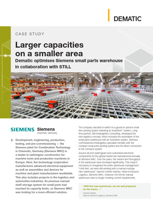
SiemensChemnitz, GermanyLarger capacities on a smaller areaDematic optimises Siemens small parts warehouse in collaboration with STILLThe company decided to switch to a goods-to-person small item picking system featuring an AutoStore ™ system. Long-time partner, Still Intralogistics Consulting, developed the new logistics concept, which included the automation of the small parts warehouse with an AutoStore system. Siemens commissioned intralogistics specialist Dematic with thecompact small parts picking system and the direct connection to the conveyor system.Around 46,000 switchgears and customised electroniccomponents for the global market are manufactured annually at Siemens WKC. Over the years, the volume and throughput in the warehouse have increased significantly. This made it necessary to reorganise the entire warehouse management: “Until then, we were still working with a manual modular rack warehouse,” reports Carsten Sambo, Head of Inbound Logistics, Siemens WKC. However, the former manual warehouse was no longer meeting current requirements.Development, engineering, production,testing, and pre-commissioning — theSiemens plant for Combination Technology in Chemnitz, Germany (Siemens WKC) is a leader in switchgear construction for machine tools and production machines in Europe. Here, the technology corporation manufactures advanced electrical equipment as well as assemblies and devices formachine and plant manufacturers worldwide. This also includes projects in the logistics and automotive industries. Its previous manual shelf storage system for small parts hadreached its capacity limits, so Siemens WKC was looking for a more efficient solution.“With the new warehouse, we are well prepared for the future ...”Carsten SamboHead of Inbound Logistics, Siemens WKCC A S E S T UD YAutomation of the Production Warehouse with AutoStoreSiemens initiated the search for a new solution: “Our goal was to make planning and production as efficient as possible. At the same time, the lead time was to be reduced and, of course, the costs were to be lowered,” explains Sambo. The new storage systems, including the conveyor technology, needed to be installed on the same floor space in the existing building and during ongoing operations.Long-time partner, Still Intralogistics Consulting, took on the initial planning of the logistics concept. This included automating the small parts warehouse with an AutoStoresystem to improve the supply of small parts to production. “We already had very good experience with an AutoStore storage system at a Siemens plant in Bad Neustadt (EWN),” explains Sambo. It accommodates up to four times more stock than the previous manual system. After only a short introductory phase, the Siemens WKC also achieved improved picking performance with 75 retrieval positions per hour (previously only 30 retrieval positions per hour). With the help of thesystem, this performance will increase by at least another 15 per cent.As a global distribution partner for AutoStore, Dematic was brought in for its extensive experience and expertise. Siemens commissioned Dematic (a sister company of STILL in the KION Group) as a system integrator to implement the AutoStore system and connect it using Dematic conveyor technology for automation that optimizes the material flow for production supply. A major advantage of this unit load picking solution is that it requires very little space. Siemens can use the space gained for storing larger material items, such as enclosures for switchgear. STILL supplied a racking system for around 12,000 storage locations and 2,100 square metres of platform space as part of the overall logistics concept. Capacities significantly increasedThe conveyor system implemented by Dematic has two levels. In the goods receiving area, incoming parcels are first scanned and transported to the upper level via a lift. There, the goods are automatically and randomly distributed to the eight transfer stations. Empty AutoStore totes from the lower level go to the workstations. The totes are loaded with inventory and conveyed to the automatic small parts store. A scale checks the weight of the totes to ensure that they do not exceed the permissible maximum weight of 30 kilograms. Transfer cells automatically deliver the totes into the AutoStore system where the mobile robots can then take the inventory and store it. The compact AutoStore system itself occupies an area of only 760 square metres. It contains a total of more than 45,000 bins, which are divided into different compartments and can thus hold several different products.With a request comes from production, the picking process starts — the provision of goods to the internal logistics, which prepares the materials according to production requirements and makes them available for production. The inventory for the orders are collected by the 34 mobile robots that travel on top of the AutoStore system. They pick the boxes from the grid and bring them to the port, where employees can carry out their picking activities without interruption. Previously, they had to travel long distances to pick the individual items. With the same number of employees, Siemens can now handle more orders in less time. “The system is highly efficient and with significantly fewer errors in the picking process,” says CarstenSambo.TECHNICAL DATA • 8 Transfer Stations• AutoStore ® foot print: 760 suqare metres • 45,000 bins • 34 robots • 5 picking ports•7.000 different picking positions dailyp o w e r t h e f u t u r e o f c o m m e r c e d e m a t i c .c o m2O r d e r -N o . C E _C S -1080-E N | 09/21 +49 69 583025-0CUSTOMER BENEFITS • Four times more stock in the same floor space• No more unproductive walking routes • Lower error rate• Decentralised organisation of robots minimises downtime• Modular design allows for easy expandability •Forecasting function and night shift reallocation allows faster access to the required goodsABOUT THE CUSTOMERThe Siemens Systems Engineering Plant (WKC) in Chemnitz has a long tradition in controlcabinet construction for machine tools as well as a wide range of industries in general mechanical and plant engineering. This also includesprojects in the logistics and automotive sectors. The range of services includes the completespectrum from application engineering, material logistics and assembly of electrical equipment to testing and pre-commissioning. Deliveries are made to customers worldwide. The specific scope of services is determined individually by the respective customer on an order-by-order basis. WKC is also a recognized competence centre for the climatization of control cabinets. It has his own test laboratory with associated possibilities for performing load test. WKC is in addition a certified UL panel shop.Equipped for the futureThe AutoStore system can store up to four times more stock in the same footprint than conventional storage systems.“The cube-storage system is a self-supporting aluminium grid whose modular structure allows containers to be stacked closely next to and on top of each other. Furthermore, it is organised in a decentralised manner — if a robot breaksdown, the system continues to run,” explains Sambo, adding, “We have daily call-offs of more than 7,000 different picking positions. To be able to access the required goods quickly in the morning, we have programmed a forecast function for stock removal or night shift transfer.” Overnight, the demand for the next day is checked. The determined materials are transferred from the lowest levels of the AutoStore system to the upper area of the grid. “This ensures that the required containers can be accessed quickly with the start of the early shift.”The small parts warehouse concept was developed with close collaboration among Siemens, Dematic, and STILL. In the end, Sambo sums it up, “We are now well prepared for the future, with scalability already taken into account during the planning stage. We’ve been able to increase the storage and picking capacities as well as make the entire warehouse management more efficient.” The fact that the production supply was maintained without interruptions during installation was a personal highlight for the Siemens project manager.。
NX-series EtherCAT Coupler Unit用户手册说明书
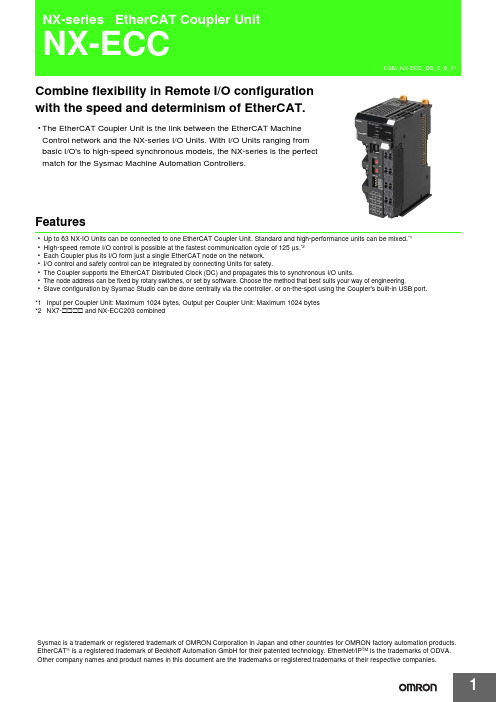
Combine flexibility in Remote I/O configurationwith the speed and determinism of EtherCAT.•The EtherCAT Coupler Unit is the link between the EtherCAT MachineControl network and the NX-series I/O Units. With I/O Units ranging frombasic I/O's to high-speed synchronous models, the NX-series is the perfectmatch for the Sysmac Machine Automation Controllers.Features•Up to 63 NX-IO Units can be connected to one EtherCAT Coupler Unit. Standard and high-performance units can be mixed.*1•High-speed remote I/O control is possible at the fastest communication cycle of 125 μs.*2•Each Coupler plus its I/O form just a single EtherCAT node on the network.•I/O control and safety control can be integrated by connecting Units for safety.•The Coupler supports the EtherCAT Distributed Clock (DC) and propagates this to synchronous I/O units.•The node address can be fixed by rotary switches, or set by software. Choose the method that best suits your way of engineering.•Slave configuration by Sysmac Studio can be done centrally via the controller, or on-the-spot using the Coupler's built-in USB port.*1Input per Coupler Unit: Maximum 1024 bytes, Output per Coupler Unit: Maximum 1024 bytes*2NX7-@@@@ and NX-ECC203 combinedSysmac is a trademark or registered trademark of OMRON Corporation in Japan and other countries for OMRON factory automation products. EtherCAT is a registered trademark of Beckhoff Automation GmbH for their patented technology. EtherNet/IP TM is the trademarks of ODVA. Other company names and product names in this document are the trademarks or registered trademarks of their respective companies.System ConfigurationSystem Configuration of Slave TerminalsThe following figure shows an example of the system configuration when an EtherCAT Coupler Unit is used as a Communications Coupler Unit.*1.The connection method for the Sysmac Studio depends on the model of the CPU Unit or Industrial PC.*2.An EtherCAT Slave Terminal cannot be connected to any of the OMRON CJ1W-NC @81/@82 Position Control Units even though they canoperate as EtherCAT masters.*3.For whether NX Units can be connected to the CPU Unit or Communications Coupler Unit to be used, refer to the user's manual for the CPUUnit or Communications Coupler Unit to be used.EtherCAT master *2Sysmac Studio Support SoftwareOrdering InformationApplicable standardsRefer to the OMRON website () or ask your OMRON representative for the most recent applicable standards for each model.*1.This depends on the specifications of the EtherCAT master. For example, the values are as follows when the EtherCAT Coupler Unit isconnected to the built-in EtherCAT port on an NJ5-series CPU Unit: 500 μs, 1,000 μs, 2,000 μs, and 4,000 μs. Refer to the NJ/NX-series CPU Unit Built-in EtherCAT Port User’s Manual (Cat. No. W505) for the specifications of the built-in EtherCAT ports on NJ/NX-series CPU Units.*2.This depends on the Unit configuration.Recommended EtherCAT Communications CableUse a straight STP (shielded twisted-pair) cable of category 5 or higher with double shielding (braiding and aluminum foil tape) for EtherCAT.Cable with Connectors*1.Standard type cables length 0.2, 0.3, 0.5, 1, 1.5, 2, 3, 5, 7.5, 10, 15 and 20 m are available.Rugged type cables length 0.3, 0.5, 1, 2, 3, 5, 10 and 15 m are available.For details, refer to Cat.No.G019.*2.The lineup features Low Smoke Zero Halogen cables for in-cabinet use and PUR cables for out-of-cabinet use. Although the LSZH cable issingle shielded, its communications and noise characteristics meet the standards.*3.Cables colors are available in blue, yellow, or Green.*4.For details, contact your OMRON representative.Product nameCommunications cycle inDC Mode *1 *2Current consumptionMaximum I/O power supply current Model EtherCAT Coupler Unit250 to 4,000 μs 1.45 W or lower4 ANX-ECC20110 ANX-ECC202125 to 10,000 μs 1.25 W or lower NX-ECC203ItemAppearanceRecommended manufacturerCable length [m] *1ModelCable with Connectors on Both Ends (RJ45/RJ45)Standard RJ45 plugs type *1Wire gauge and number of pairs: AWG26, 4-pair cable Cable sheath material: LSZH *2Cable color: Yellow *3OMRON0.3XS6W-6LSZH8SS30CM-Y 0.5XS6W-6LSZH8SS50CM-Y 1XS6W-6LSZH8SS100CM-Y 2XS6W-6LSZH8SS200CM-Y 3XS6W-6LSZH8SS300CM-Y 5XS6W-6LSZH8SS500CM-Y Cable with Connectors on Both Ends (RJ45/RJ45)Rugged RJ45 plugs type *1Wire gauge and number of pairs: AWG22, 2-pair cable Cable color: Light blueOMRON0.3XS5W-T421-AMD-K 0.5XS5W-T421-BMD-K 1XS5W-T421-CMD-K 2XS5W-T421-DMD-K 5XS5W-T421-GMD-K 10XS5W-T421-JMD-K Cable with Connectors on Both Ends (M12 Straight/M12 Straight)Shield Strengthening Connector cable *4M12/Smartclick ConnectorsWire Gauge and Number of Pairs: AWG22, 2-pair Cable Cable color: BlackOMRON0.5XS5W-T421-BM2-SS 1XS5W-T421-CM2-SS 2XS5W-T421-DM2-SS 3XS5W-T421-EM2-SS 5XS5W-T421-GM2-SS 10XS5W-T421-JM2-SS Cable with Connectors on Both Ends (M12 Straight/RJ45)Shield Strengthening Connector cable *4M12/Smartclick Connectors Rugged RJ45 plugs typeWire Gauge and Number of Pairs: AWG22, 2-pair Cable Cable color: BlackOMRON0.5XS5W-T421-BMC-SS 1XS5W-T421-CMC-SS 2XS5W-T421-DMC-SS 3XS5W-T421-EMC-SS 5XS5W-T421-GMC-SS 10XS5W-T421-JMC-SSCables / ConnectorsWire Gauge and Number of Pairs: AWG24, 4-pair Cable*We recommend you to use above cable and connector together.Wire Gauge and Number of Pairs: AWG22, 2-pair Cable*We recommend you to use above cable and connector together.Note:Connect both ends of cable shielded wires to the connector hoods.Optional ProductsAccessoriesEnd Cover (NX-END01)An End Cover is connected to the end of the EtherCAT Slave Terminal.One End Cover is provided together with the EtherCAT Coupler Unit.ItemAppearanceRecommended manufacturerModelCables-Hitachi Metals, STAR-C5E SAB 0.5 × 4P CP *-Kuramo Electric Co.KETH-SB *-SWCC Showa Cable Systems Co.FAE-5004 *RJ45 Connectors-Panduit CorporationMPS588-C *ItemAppearanceRecommended manufacturer ModelCables-Kuramo Electric Co.KETH-PSB-OMR *-JMACS Japan Co., Ltd.PNET/B *RJ45 Assembly ConnectorOMRONXS6G-T421-1 *Product nameSpecificationModelUnit/Terminal Block Coding PinsPins for 10 Units(30 terminal block pins and 30 Unit pins)NX-AUX02Product NameSpecificationModelNo. of terminals Ground terminal mark Terminal current capacity Terminal Block8Present10 ANX-TBC082General Specification*Refer to the OMRON website (/) or consult your OMRON representative for the most recent applicable standards for each model.SpecificationsEtherCAT Coupler Unit NX-ECC201/NX-ECC202/NX-ECC203*1.Refer to the NX-series Safety Control Units User’s Manual (Cat. No. Z930) for the number of Safety Control Units that can be connected.*2.This function was added or improved for a version upgrade. Refer to the NX-series EtherCAT Coupler Unit User’s Manual (Cat. No. W519) forinformation on version upgrades.*3.The range of node addresses that can be set depends on the model of the built-in EtherCAT port. For the node address ranges that can beset for a built-in EtherCAT port, refer to the user's manual for the built-in EtherCAT port on the connected CPU Unit or Industrial PC.*4.This depends on the specifications of the EtherCAT master. For example, the values are as follows when the EtherCAT Coupler Unit isconnected to the built-in EtherCAT port on an NJ5-series CPU Unit: 500 μs, 1,000 μs, 2,000 μs, and 4,000 μs. For the specifications of the built-in EtherCAT port, refer to the user's manual for the built-in EtherCAT port on the connected CPU Unit or the Industrial PC.*5.This depends on the Unit configuration.*6.There are restrictions in the communications cycles that you can set for some of the NX Units. If you use any of those NX Units, set acommunications cycle that will satisfy the specifications for the refresh cycles that can be executed by the NX Unit. Refer to the appendix of the NX-series Data Reference Manual (Cat. No. W525-E1-07 or later) to see if there are restrictions on any specific NX Units. For information on the communications cycles that you can set, refer to the user’s manuals for the NX Units.*7.Refer to the NX-series EtherCAT Coupler Unit User’s Manual (Cat. No. W519) for procedures for designing the Unit power supply system andI/O power supply system.*e a voltage that is appropriate for the I/O circuits of the NX Units and the connected external devices.ItemSpecificationEnclosureMounted in a panel Grounding methodGround to 100 Ω or less Operating environmentAmbient operating temperature 0 to 55°CAmbient operating humidity 10% to 95% (with no condensation or icing)AtmosphereMust be free from corrosive gases.Ambient storage temperature −25 to 70°C (with no condensation or icing)Altitude2,000 m max.Pollution degree Pollution degree 2 or less: Meets IEC 61010-2-201.Noise immunity Conforms to IEC61000-4-4. 2 kV (power supply line)Overvoltage category Category II: Meets IEC 61010-2-201.EMC immunity level Zone BVibration resistance Conforms to IEC 60068-2-6.5 to 8.4 Hz with 3.5-mm amplitude, 8.4 to 150 Hz, acceleration of 9.8 m/s 2, 100 min each in X, Y, and Z directions (10 sweeps of 10 min each = 100 min total)Shock resistanceConforms to IEC 60068-2-27. 147 m/s 2, 3 times each in X, Y, and Z directions Applicable standards *cULus: Listed (UL 508 or UL61010-2-201), ANSI/ISA 12.12.01,EU: EN 61131-2, C-Tick or RCM, KC Registration, NK, and LRItemSpecificationNX-ECC201NX-ECC202NX-ECC203Number of connectable NX Units 63 Units max.*1Send/receive PDO data sizes Input: 1,024 bytes max. (including input data, status, and unused areas)Output: 1,024 bytes max. (including output data and unused areas)Mailbox data size Input: 256 bytes Output: 256 bytesMailboxEmergency messages and SDO requestsRefreshing methods *2•Free-Run refreshing •Synchronous I/O refreshing •Time stamp refreshing•Free-Run refreshing•Synchronous I/O refreshing •Time stamp refreshing •Task period prioritized refreshingNode address setting rangeWhen the settable node address range for the built-in EtherCAT port is 1 to 512*3•Set on switches: 1 to 199•Set with the Sysmac Studio: 1 to 512When the settable node address range for the built-in EtherCAT port is 1 to 192*3•Set on switches: 1 to 192•Set with the Sysmac Studio: 1 to 192I/O jitter performanceInputs: 1 μs max.Outputs: 1 μs munications cycle in DC Mode250 to 4,000 μs *4 *5125 to 10,000 μs *3 *4 *6Unit power supply *7Power supply voltage24 VDC (20.4 to 28.8 VDC)NX Unit power supply capacity10 W max.Refer to Installation orientation and restrictions for details.NX Unit power supply efficiency 70%Isolation methodNo isolation between NX Unit power supply and Unit power supply terminals Current capacity of power supply terminals4 A max.I/O powersupply *7Power supply voltage5 to 24 VDC (4.5 to 28.8 VDC) *8Maximum I/O power supply current4 A 10 A Current capacity of power supply terminals4 A max.10 A max.NX Unit power consumption1.45 W max. 1.25 W max.Current consumption from I/O power supply 10 mA max. (for 24 VDC)Dielectric strength 510 VAC for 1 min, leakage current: 5 mA max. (between isolated circuits)Insulation resistance100 VDC, 20 M Ω min. (between isolated circuits)EtherCAT Communications Specifications*The EtherCAT Coupler Unit conforms to EtherCAT standards. Check the specifications of the EtherCAT master being connected for the configurable topology. However, note that only NX-ECC203 EtherCAT Coupler Units (Ver. 1.5 or later) is compatible with a ring topology.Version InformationNote:Some Units do not have all of the versions given in the above table. If a Unit does not have the specified version, support is provided by theoldest available version after the specified version. Refer to the user's manuals for the specific Units for the relation between models and versions.*1For the NX-ECC202, there is no unit version of 1.1 or earlier.*2For the NX-ECC203, there is no unit version of 1.2 or earlier.ItemSpecificationCommunications standard IEC 61158 Type 12Physical layer 100BASE-TX (IEEE 802.3)Modulation Baseband Baud rate 100 MbpsTopologyDepends on the specifications of the EtherCAT master. *Transmission mediaCategory 5 or higher twisted-pair cable (Recommended cable: double-shielded cable with aluminum tape and braiding)Transmission distance Distance between nodes: 100 m or lessModel number of EtherCAT Coupler UnitUnit version Corresponding versionsUsing an NX-series CPU Unit Using an NJ-series CPU Unit Using an NY-series Industrial PC Unit version of CPU UnitSysmac StudioversionUnit version of CPU Unit Sysmac Studioversion Unit version of Industrial PCSysmac StudioversionNX-ECC201Ver. 1.2Ver. 1.10Ver. 1.13Ver. 1.07Ver. 1.08Ver. 1.12Ver. 1.17Ver. 1.1Ver. 1.06Ver. 1.07Ver. 1.0Ver. 1.05Ver. 1.06NX-ECC202Ver. 1.2*1Ver. 1.07Ver. 1.08NX-ECC203Ver. 1.7Ver. 1.41Ver. 1.41Ver. 1.41Ver. 1.6Ver. 1.25Ver. 1.25Ver. 1.25Ver. 1.5Ver. 1.19Ver. 1.19Ver. 1.19Ver. 1.4Ver. 1.16Ver. 1.16Ver. 1.17Ver. 1.3*2Ver. 1.13Ver. 1.13External InterfaceEtherCAT Coupler Unit NX-ECC20@Terminal BlockApplicable Terminal Blocks for Each Unit ModelSymbol NameFunction(A)NX bus connectorThis connector is used to connect each Unit.(B)IndicatorsThe indicators show the current operating status of the Unit.(C)Communications connectors These connectors are connected to the communications cables of the EtherCAT network.There are two connectors, one for the input port and one for the output port.(D)Peripheral USB port This port is used to connect to the Sysmac Studio Support Software.(E)Terminal block The terminal block is used to connect external devices.The number of terminals depends on the type of Unit.(F)Rotary switches These rotary switches are used to set the 1s digit and 10s digit of the node address of the EtherCAT Coupler Unit as an EtherCAT slave. The address is set in decimal.(G)DIP switchThe DIP switch is used to set the 100s digit of the node address of the EtherCAT Coupler Unit as an EtherCAT slave.Symbol NameFunction(A)Terminal number indications The terminal numbers (A1 to A8 and B1 to B8) are displayed.The terminal number indicators are the same regardless of the number of terminals on the terminal block, as shown above.(B)Release holes Insert a flat-blade screwdriver into these holes to connect and remove the wires.(C)Terminal holes The wires are inserted into these holes.(D)Ground terminal markThis mark indicates the ground terminals. Only the NX-TBC082 has this mark.Unit modelCurrent capacity ofUnit's power supply terminals Terminal BlocksUnit power supplyI/O power supplyModelNo. of terminalsGround terminalmark Terminal currentcapacity NX-ECC201 4 A NX-TBC0828Present 10 A NX-ECC202 or NX-ECC2034 A10 ANX-TBC0828Present10 A(B)(D)(E)Eight-terminal Block(A)NX-TBC082Applicable WiresUsing FerrulesIf you use ferrules, attach the twisted wires to them.Observe the application instructions for your ferrules for the wire stripping length when attaching ferrules.Always use plated one-pin ferrules. Do not use unplated ferrules or two-pin ferrules.The applicable ferrules, wires, and crimping tool are given in the following table.*1.Some AWG 14 wires exceed 2.0 mm 2 and cannot be used in the screwless clamping terminal block.When you use any ferrules other than those in the above table, crimp them to the twisted wires so that the following processed dimensions are achieved.Using Twisted Wires/Solid WiresIf you use the twisted wires or the solid wires, use the following table to determine the correct wire specifications.*1Secure wires to the screwless clamping terminal block. Refer to the Securing Wires in the USER'S MANUAL for how to secure wires.*2With the NX-TB @@@1 Terminal Block, use twisted wires to connect the ground terminal. Do not use a solid wire.<Additional Information> If more than 2 A will flow on the wires, use plated wires or use ferrules.Terminal typesManufacturerFerrule model Applicable wire (mm 2 (AWG))Crimping toolTerminals other than ground terminalsPhoenix Contact AI0,34-80.34 (#22)Phoenix Contact (The figure in parentheses is the applicable wire size.)CRIMPFOX 6 (0.25 to 6 mm 2, AWG 24 to 10)AI0,5-80.5 (#20)AI0,5-10AI0,75-80.75 (#18)AI0,75-10AI1,0-8 1.0 (#18)AI1,0-10AI1,5-8 1.5 (#16)AI1,5-10Ground terminalsAI2,5-102.0 *1Terminals other than ground terminalsWeidmuller H0.14/120.14 (#26)Weidmueller (The figure in parentheses is the applicable wire size.)PZ6 Roto (0.14 to 6 mm 2, AWG 26 to 10)H0.25/120.25 (#24)H0.34/120.34 (#22)H0.5/140.5 (#20)H0.5/16H0.75/140.75 (#18)H0.75/16H1.0/14 1.0 (#18)H1.0/16H1.5/14 1.5 (#16)H1.5/16TerminalsWire typeWire sizeConductor length(stripping length)Twisted wires Solid wire Classification Current capacity Plated Unplated Plated UnplatedAll terminals except ground terminals2 A max.Possible Possible Possible Possible0.08 to 1.5 mm 2AWG28 to 168 to 10 mmGreater than2 A and 4 A or less Not Possible Possible*1NotPossible Greater than 4 A Possible *1NotPossibleGround terminals ---Possible PossiblePossible *2Possible*22.0 mm 29 to 10 mm1.6 mm max.2.0 mm max.(Ground terminals)(Ground terminals)Conductor length (stripping length)Dimensions(Unit: mm)EtherCAT Coupler Unit● EtherCAT Coupler Unit Only*The dimension is 1.35 mm for Units with lot numbers through December 2014.● With Cables Connected*1.*2.•• 1.5NX-ECC 11End Cover*This is the shape for Units with lot numbers through December 2014.Related Manuals Man. No Model Manual ApplicationDescription W519NX-ECC20@NX-series EtherCAT Coupler Unit User’s ManualLeaning how to use anNX-series EtherCATCoupler Unit andEther-CAT Slave Terminals The following items are described: the overall system and configuration methods of an EtherCAT Slave Terminal (which consists of an NX-series EtherCAT Coupler Unit and NX Units), and information on hardware, setup, and functions to setup, control, and monitor NX Units through EtherCAT.2020.6In the interest of product improvement, specifications are subject to change without notice. OMRON CorporationIndustrial Automation Company/(c)Copyright OMRON Corporation 2020 All Right Reserved.。
1、appendix-2

• 经销商选择与支持 • 经销商调查(品质、服务水平) • 经销商关系与控制培训
经销商管理支持
• 经销商管理培训(职能、责任、可靠性、经济 关系)
• 招聘协助 • 经销商客户服务培训
经销商技术支持
• 产品知识 • 技术(技师) • 服务过程(督导) • 服务经济学
经销商后勤支持
• 预测/后勤培训 • 存货管理培训
1,000-3,000 500-1,500
206
本田
三菱
100-125
15-50
1,000-1,500 500-900 74
50-75 60:40 30-50 80:20 50-600 300-400 154 (+11 在建设中)
*现代 20-50
5-15
200-3 00 50-100
70
*仅为大体估计
MMC •轿车交货30天后 •皮卡车交货60天后
现代 •交货后30天
,5万公里(车身、 车漆、机械件
•活动经费 •配件折扣 •其他许多
•3-4%
•2年,5万公里(车身、 车漆、机械件
•在百货商店/车展布置展 区
丰田克罗那G Xi(自动传动)车的价值链
100% 90%
经销商卖新车利润
担保
•3-5%
• 2年,5万公里(车 身、车漆、机械件)
经销商销售 •经销商和买主融资 •促销费用 20,000/次(自 主支付) •其他
•第一阶段:2% •第二阶段:2.5% •最大:3%
•2年,5万公里(车身、 车漆、机械件)
•在广告和活动支持方面反 复无常 •经销商负担一切费用
担保 订货程序 库存 支付条款 运输
•2年或50,000公里,任一个先达到 •车身、车漆、机械部件 •向客户提供保修服务卷:只可支付劳工费用(不包括油、漏油器等其他) •1995年1月推出“新的订货生产和运输系统”(OPT) •经销商需要在交货1个月前预订 •订单被输入计算机,然后根据提交先后顺序分配车 •还有许多问题-许多经销商有大量压单(在Chiang Mai有350多),而且客户要等60天
KOD高保真酶说明书

JAPAN CHINATOYOBO CO., LTD. TOYOBO Bio-Technology, CO., LTD.Tel(81)-6-6348-3888 Tel(86)-21-58794900.4140www.toyobo.co.jp/e/biotech_osaka@toyobo.jp1 F0934KKOD -Plus-KOD-201 200 U 200 reactionsStore at -20°C Contents[1]Introduction[2]Components[3]Quality testing[4]Primer design[5]Cloning of PCR products[6]Protocol1. Standard reaction setup2. Cycling conditions[7]Examples[8]Troubleshooting[9] References[10] Related productsC AUSIONAll reagents in this kit are intended for research purposes. Do not use for diagnosis or clinical purposes. Please observe general laboratory precaution and utilize safety while using this kit.JAPAN CHINATOYOBO CO., LTD. TOYOBO Bio-Technology, CO., LTD.Tel(81)-6-6348-3888 Tel(86)-21-58794900.4140www.toyobo.co.jp/e/biotech_osaka@toyobo.jp 1[ 1 ] Introduction[ 2 ] Components [ 3 ] Quality Testing DescriptionKOD -Plus- is based on DNA polymerase from the hyperthermophilic Archaeon Thermococcus kodakaraensis KOD11) 2). KOD -Plus- exhibits excellent high PCR fidelity and efficiency. The enzyme solution of KOD -Plus- contains two types of anti-KOD DNA polymerase antibodies that inhibit polymerase and 3’J5’ exonuclease activity, thus allowing for Hot Start PCR3). KOD -Plus- generates blunt-end PCR products, due to 3’J5’ exonuclease (proof-reading) activity.Features-Hot Start technology, using anti-KOD DNA polymerase antibodies, results in highly efficient amplification (see Example 1).-KOD -Plus- enables the following amplifications (maximum): 21 kb from lambda phage DNA, 12 kb from human genomic DNA, and 7 kb from cDNA.-KOD DNA polymerase has strong 3’J5’ exonuclease (proof-reading) activity. The PCR error ratio of KOD -Plus- is approx. 80 times less than Taq DNA polymerase.Table. 1 PCR fidelity comparison of each PCR enzyme.*PCR fidelity was based on the mutation frequency of PCR products using a positive-selection base assay with the rpsL gene 4).This reagent includes the following components for 200 reactions:KOD -Plus- (1.0 U/μl) * 200 μl × 110× Buffer for KOD -Plus- 1.0 ml × 125 mM MgSO4 1.0 ml × 12 mM dNTPs 1.0 ml × 1*The enzyme solution contains anti-KOD DNA polymerase antibodies that neutralize polymerase and 3’J5’ exonuclease activity.Quality check can be performed by amplifying the β-globin gene (3.6 Kb) and p53 gene (4.0 Kb).JAPAN CHINATOYOBO CO., LTD. TOYOBO Bio-Technology, CO., LTD.Tel(81)-6-6348-3888 Tel(86)-21-58794900.4140www.toyobo.co.jp/e/biotech_osaka@toyobo.jp 2[ 4 ] Primer Design[ 5 ] Cloning ofPCR products [ 6 ] Protocol -Primers should be 22-34 bases with a melting temperature (Tm) over 60°C. For amplification of a long target, 25-34 bases with high Tm values (≥ 65°C) are recommended. PCR primers should be designed according to the general guidelines.-KOD-Plus- generates blunt-end PCR products, due to 3’J5’ exonuclease (proof- reading) activity. Therefore, the product can be cloned according to a blunt-end cloning method.-PCR products of KOD-Plus- should be purified prior to restriction enzyme treatments. The 3’J5’ exonuclease activity of KOD DNA polymerase remains after the PCR cycles.1. Standard reaction setupThe following procedure is designed for use with the components provided in this kit. Before preparing mixture, all components should be completely thawed, except for the enzyme solution.* Do not use dNTPs from other kits or companies.Notes:-For PCR reactions, thin-wall tubes are recommended. A total reaction volume of 50 μl is also recommended.-The addition of DMSO (final conc. 2-5%) might be effective for amplification of GC-rich targets. Decreased PCR fidelity has been confirmed to not take place with DMSO.-Contaminated RNA (used for cDNA) or genomic DNA inhibits the PCR reaction by chelating Mg2+. PCR should be performed using template DNA containing <100 ng RNA component.Component Volume FinalConcentration 10x Buffer for KOD -Plus- 5 μl 1x2mM dNTPs* 5 μl 0.2 mM each25mM MgSO4 2μl 1.0mM10pmol/μl Primer #1 1.5 μl 0.3 μM10pmol/μl Primer #2 1.5 μl 0.3 μMTemplate DNA X μlGenomic DNA 10-200 ng/50 μlPlasmid DNA 1-50 ng/50 μlcDNA ≤ 100 ng (RNA equiv.)/50 μl PCR grade water Y μlKOD-Plus- (1.0 U/μl) 1μl 1.0 U / 50 μlTotal reaction volume 50 μlJAPAN CHINA TOYOBO CO., LTD. TOYOBO Bio-Technology, CO., LTD.Tel(81)-6-6348-3888 Tel(86)-21-58794900.4140 www.toyobo.co.jp/e/biotech_osaka@toyobo.jp32. Cycling conditionsThe following cycling steps are recommended.Note : If the Tm value of the primer is under 73 °C, the 3-step cycle is recommended.*Tm value of the primer minus 5°C-10°CNotes:-Extension time should be set to 1min per 1 kb of target length.< 2-step cycle >Pre-denaturation: 94 °C , 2 min. Denaturation: 94 °C, 15 sec. Extension:68 °C, 1 min./kb< 3-step cycle >Pre-denaturation: 94 °C, 2 min. Denaturation: 94 °C, 15 sec.Annealing: Tm-[5-10]oC*, 30 sec.Extension:68 °C, 1 min./kb25-35 cyclesJAPAN CHINA TOYOBO CO., LTD. TOYOBO Bio-Technology, CO., LTD.Tel(81)-6-6348-3888 Tel(86)-21-58794900.4140 www.toyobo.co.jp/e/biotech_osaka@toyobo.jp4[ 7 ] ExamplesExample 1.Effect of Hot Start PCR on the generation of primer dimers.Example 2. Effect of addition of DMSO for GC-rich targets.M: 1kb Template: Human genomic DNA Target: TGF-βgene (GC%=70) 2kb Ladder Markers 1: KOD -Plus-, 0% DMSO 2: KOD -Plus-, 2% DMSO 3: KOD -Plus-, 5% DMSOM 1 2 3M 123456MJAPAN CHINA TOYOBO CO., LTD. TOYOBO Bio-Technology, CO., LTD.Tel(81)-6-6348-3888 Tel(86)-21-58794900.4140 www.toyobo.co.jp/e/biotech_osaka@toyobo.jp5[ 8 ] Troubleshooting[ 9 ] References1)Takagi M, Nishioka M, Kakihara H, Kitabayashi M, Inoue H, Kawakami B, Oka M, and Imanaka T., Appl Environ Microbiol., 63: 4504-10 (1997)2)Hashimoto H, Nishioka M, Fujiwara S, Takagi M, Imanaka T, Inoue T and Kai Y , J Mol Biol ., 306: 469-77 (2001)3)Mizuguchi H, Nakatsuji M, Fujiwara S, Takagi M and Imanaka T, J Biochem ., 126: 762-8 (1999)4)Fujii S, Akiyama M, Aoki K, Sugaya Y , Higuchi K, Hiraoka M, Miki Y , Saitoh N, Yoshiyama K, Ihara K, Seki M, Ohtsubo E and Maki H, J. Mol. Bio l., 289: 835-850 (1999)SymptomCauseSolutionLower annealing temperature increments to a maximum of Tm-10°C.Cycling conditions are not suitable.Increase the number of cycles by 2-5 cycles. Mg concentration is low Increase the Mg concentration to 1.2-2 mM. High GC content of target sequenceAdd DMSO 2-5%. <See Example 2>Check the quality of primers. Primer is not good.Redesign primers.Check the quality of template DNA. RNA inhibits amplification.No PCR product/low yield Quality and/or quantity of template DNA is not sufficient.Increase the amount of template DNA.Decrease the number of cycles by 2-5 cycles. Cycling condition is not suitable.Use step-down cycling.Check the quality of primers. Primer is not good.Redesign primers.Too much template DNA Reduce the amount of template DNA. Too much Mg Reduce MgSO 4 to 0.8 mM.Smearing/extra bandToo much enzymeReduce enzyme to 0.5-0.8 U/50 μl.Poor TA cloning efficiency PCR products have blunt- ends.Clone the PCR products according to general blunt- end cloning guidelines.JAPAN CHINA TOYOBO CO., LTD. TOYOBO Bio-Technology, CO., LTD.Tel(81)-6-6348-3888 Tel(86)-21-58794900.4140 www.toyobo.co.jp/e/biotech_osaka@toyobo.jp6[ 10 ] Related productsProduct namePackage Code No. TArget Clone -Plus- 10 reactions TAK-201 10x A-attachment mix 25 reactions TAK-301 Ligation high Ver.2750 μl(100 reactions)LGK-201TArget Clone -Plus- is a high efficient TA cloning kit. The kit can be applied to the TA cloning of blunt-end PCR products amplified using KOD -Plus- [Code No. KOD-201] or KOD FX [Code No. KFX-101]. The kit contains pTA2 Vector, 2x Ligation Buffer, T4 DNA Ligase and 10x A-attachment Mix.10 x A-attachment mix is a reagent comprising anti-KOD DNA polymerase antibody specific to KOD 3’J 5’ exonuclease activity (proof-reading activity), as well as Taq DNA polymerase, which exhibits terminal transferase activity. PCR products from KOD -Plus- [Code No. KOD-201] and KOD FX [Code No. KFX-101] possess blunt ends due to 3’J 5’ exonuclease activity of the KOD DNA polymerase. The 10 x A-attachment mix allows for PCR products to acquire overhanging dA at the 3’-ends. Products with 3’-dA overhangs can be directly cloned into arbitrary T-vectors using ligation reagents, such as Ligation high Ver.2 [Code No. LGK-201].Fig. Principle of the 10 x A-attachment mixAnti-KOD DNA polymeraseAJAPAN CHINATOYOBO CO., LTD. TOYOBO Bio-Technology, CO., LTD.Tel(81)-6-6348-3888 Tel(86)-21-58794900.4140www.toyobo.co.jp/e/biotech_osaka@toyobo.jp 7NOTICE TO PURCHASER: LIMITED LICENSEUse of this product is covered by one or more of the following US patents and corresponding patent claims outside the US: 5,079,352, 5,789,224, 5,618,711, 6,127,155 and claims outside the US corresponding to US Patent No. 4,889,818.The purchase of this product includes a limited, non-transferable immunity from suit under the foregoing patent claims for using only this amount of product for the purchaser’s own internal research. No right under any other patent claim (such as the patented 5’ Nuclease Process claims in US Patents Nos. 5,210,015 and 5,487,972), no right to perform any patented method, and no right to perform commercial services of any kind, including without limitation reporting the results of purchaser's activities for a fee or other commercial consideration, is conveyed expressly, by implication, or by estoppel. This product is for research use only. Diagnostic uses under Roche patents require a separate license from Roche. Further information on purchasing licenses may be obtained by contacting the Director of Licensing, Applied Biosystems, 850 Lincoln Centre Drive, Foster City, California 94404, USA.。
外企模具检查清单-英文版Mold test checklist
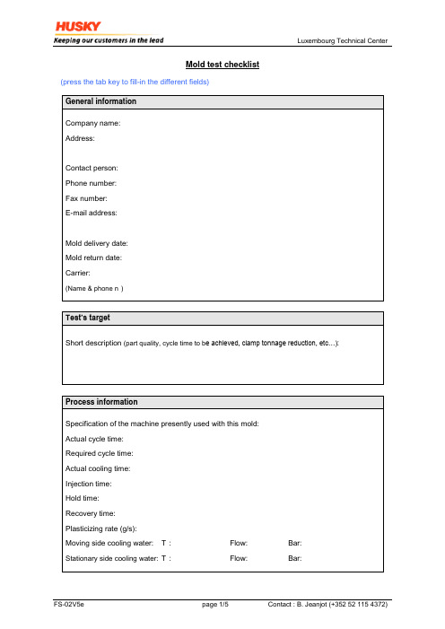
Luxembourg Technical CenterMold test checklist(press the tab key to fill-in the different fields)Luxembourg Technical CenterMold informationMold maker:Mold type: Stack mold Standard mold (2 platens)If stack mold, please specify section dimension of the sprue bar:Mold mounting pattern: Clamps Euromap (screw)Minimum stroke for free drop:Mold size:Height (L): mmWidth (B): mmShutheight HR+HL: mmWeight: KgLocating ring diameter:Moving platen:Stationary platen:Locating ring thickness: Moving platen: Stationary platen:Are both locating rings removable Yes NOMold cooling informationQuantity of cooling circuit: Moving platen: Stationary platen:Water fitting: DME Hasco Staubli OtherWater fitting size:Luxembourg Technical CenterMold informationAir functions informationNumber of air functions: Moving platen: Stationary platen:Air fitting required: Type: Size:Hot runner informationMold equipped with a Hot Runner: Yes NoHot Runner system type:Husky DME Hasco Manner Other Number of heating zones:Will controller & cables be delivered: Yes NoIf not, please add electrical drawings of connectors, heaters and T/CHot runner with valve gate: Yes NoSequential injection: Yes NoNumber of valve gate functions required:Valve gate functions required: Hydraulic Pneumatic None Nozzle informationNozzle description: Radius: Orifice: (D) Protrusion (T) Please provide drawing of injection nozzle used for that mold。
- 1、下载文档前请自行甄别文档内容的完整性,平台不提供额外的编辑、内容补充、找答案等附加服务。
- 2、"仅部分预览"的文档,不可在线预览部分如存在完整性等问题,可反馈申请退款(可完整预览的文档不适用该条件!)。
- 3、如文档侵犯您的权益,请联系客服反馈,我们会尽快为您处理(人工客服工作时间:9:00-18:30)。
Conversion-instruction Functional-sequence
408727009.xls
Seite 1 von 4
Annex 10-1
Mold-delivery-checklist injection-molds
Equipment-number Vendor
Fxxxxx Zzzzzzzz
Annex 10-1
Mold-delivery-checklist injection-molds
Equipment-number Vendor Fxxxxx Zzzzzzzz Material-number Material-name xxxx-xxx-xxxx Yyyyyyyyy
Documents (send via smartlink)
Tool-clamping
Insulation-plates
Locating-rings
Ø
Ø M16x1,5 M24x1,5
Ejector-adapter Tool safe guard
Ejector-transport-securing-device Shot-counter gap existing Ring-screws Center of gravity complete mold Center of gravity injection-side Center of gravity ejection-side Center of gravity ejection-system Feet
Handling-threads at mold-inserts and heavy components Tool-centering Part-number and cavity markings Date dials acc. to SWN Ejection-side with technical polish in direction of ejection Spotting Hot-runner: correct assembly (guideline from manufacturer) Limit switches correctly assembled and adjusted408Fra bibliotek27009.xls
Seite 3 von 4
Annex 10-1 Equipment-number Vendor Electrical connections Fxxxxx Zzzzzzzz
Mold-delivery-checklist injection-molds
Material-number Material-name xxxx-xxx-xxxx Yyyyyyyyy
Hydraulic
Slides
Ejectors
Gating
IN and OUT named correctly Threads acc. to SWN Threads for leak-test Baffles made of plastic O-Ring-seats and sizes Leak-test IN and OUT named correctly Threads acc. to SWN Cylinder Merkle Typ HZ/BZ Safety Stop Marking at end-position Guidebars acc. to SWN moving at 60° C Correct assembly Prevent rotation Labelling Venting (as ordered) Coated (as ordered) Stops Guide-pillars free in mold-frame moving at 60° C as outlined in mold specification undercut sprue-ejector
Comments:
Auditor: Name 408727009.xls Date Seite 4 von 4
Material-number Material-name
xxxx-xxx-xxxx Yyyyyyyyy
Outgoing-inspection
Yes STIHL property-sign Mold-sign Vendor Material-name Material-number Equipment-number Mold-weight [kg] Dimensions EH/L/B [mm] Quick-clamping Direct-clamping Paw-clamping All holes for assembly free Mounted with TORX-screws Material Injection-side Clearance/ Depth Nozzleradius R40 Ejection-side existing Thread existing, painted orange, position all parting-levels No n/a Comments
General workmanship
Exchangeable versions Spare-parts: Position:
Hot-runner Limit-switches for hydraulic-cylinder Ejection-confirmation-switch Limit-switches for overmolded inserts Kistler pressure-sensor Kistler temperature-sensor Possibility to assemble Prybar slots Calibration Free of flash Appearance Welding Other Conversion-instruction ok all exchangeable inserts labelled Quantity: Position: Quantity:
Documents (attachments with mold-delivery)
Yes 2D-drawing mold-assembly BOM Cooling-diagram Automation-PPT Hot-runner-documents No n/a Comments
Drawings Copy of delivery papers Copy of sign
408727009.xls
Seite 2 von 4
Annex 10-1 Equipment-number Vendor Cooling Fxxxxx Zzzzzzzz
Mold-delivery-checklist injection-molds
Material-number Material-name xxxx-xxx-xxxx Yyyyyyyyy
Yes 3D-data mold-assembly 3D-data exchangeable-versions 2D-drawing mold-assembly 2D-drawings sigle parts BOM Cooling-diagram Automation-PPT Hot-runner-documents Drawings Copy of delivery papers Copy of sign Conversion-instruction Functional-sequence No n/a Comments