palmOTDR系列使用手册release_8.0
palmOTDR 系列 光时域反射仪 使用说明书 - 信维科技

palmOTDR系列光时域反射仪使用说明书Shineway Technologies, Inc. 信维科技(中国)有限公司palmOTDR系列光时域反射仪通告版权所有© 2013 ShinewayTech 保留所有权利。
根据美国及国际版权法,未经信维科技公司事先同意和书面许可,本手册的任何部分不得以任何方式或手段(包括电子存储、检索或翻译为另一种语言)进行复制。
保证本文档所含内容如有修改,恕不另告。
信维科技公司对本资料不作任何保证,包括但不限于为特定目的的适销性和适应性所作的暗示保证。
对其中包含的错误或由供给使用本资料或由版本资料的实用性而引起的偶然或继发的损失,信维科技公司不承担任何责任。
电池为易耗部件,不受palmOTDR保证的制约。
出版记录本手册的创作、出版及更新记录如下:第一版……2004年4月第二版……2005年6月第三版……2006年1月第四版……2007年8月第五版……2008年7月第六版……2010年12月第七版……2012年7月第八版……2013年2月ISO9001认证通过改进生产过程控制,使产品符合ISO9001国际质量体系标准,是我们不断提高用户满意度这一目标的组成部分。
安全须知在本仪器工作的各个阶段,都必须采取以下一般性安全措施。
不采取这些安全措施或不遵从本手册其他地方所述的特定警告,将会违反仪器设计、制造和使用的安全标准。
信维科技对于客户违反这些要求所造成的后果不承担任何责任。
总则本产品为1类安全仪器。
如不按照操作手册使用本产品,其保护功能可能会失效。
工作环境最大相对湿度95%,海拔高度达2000米。
有关AC电源电压要求和操作环境温度,请参阅技术指标表。
接通电源前确认产品设置为匹配的可用电源电压、安装了合适的熔断器并采取了所有的安全措施。
不要在易爆环境中操作不要在存在可燃性气体或烟雾时使用仪器。
不要卸下仪器外套操作人员切勿卸下仪器外罩。
更换部件和内部调整只能由合格的维修人员进行。
Palm pre多点触摸操作指南
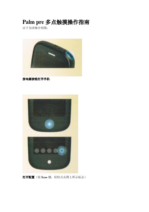
Palm pre多点触摸操作指南以下为详细介绍图:
按电源按钮打开手机
打开配置(按Home键,轻轻点击图上所示标志)
保存数据并返回上一级菜单(在手势区域向左滑动,不要超过Home键)
最小化程序并查看卡片视图(直接按Home键)
调整卡片大小,并且改变顺序(轻击卡片并且不放,拖动到想要的地方)
关闭程序(在卡片视图中,将程序甩到触摸屏上方)
打开菜单(应用菜单,轻击左上角;连接菜单,轻击右上角)
打开快速配置(Quick Launch)(从手势区慢慢向上移动,把手指移动到想配置的程序,手指离开时启动所指程序。
)
删除一个列表(将列表向左或向右扔出屏幕边界)
滚动指定行数(往想要的方向拖动)
快速滚动(轻快地向指定方向滑动)
停止滚动(在滚动中点击屏幕)
缩小操作(用两个手指触摸屏幕,并拉开它们之间的距离)
放大操作(用两个手指触摸屏幕,并让它们靠拢)
缩放到指定大小(双击放大,再次双击缩小)
在文本中定位光标(在需要的地方单击)
移动光标(插入光标,并按住橙色键,拖动到想要的地方去)
选中文字(按住shift键拖动光标到任何想要的地方)
拖放操作(轻击并不要松开欲拖拽的条目,拖至目标点后松开手指即可)。
史上最强OTDR使用详解
斜角端面 粗糙端面
反射光直线返回光源(OTDR)
肮脏端面
光纤端面质量不同,返回OTDR 的反射光强度也不同。
能够产生反射的点大体包括:机械固定接头、光纤连接器(玻璃与空气的间隙)、
6
光纤断裂、光纤的终点等
OTDR原理.工作原理
2、工作原理
OTDR类似一个光雷达。它先对光纤发出一个测试激光脉冲,然后观察 从光纤上各点返回(包括瑞利散射和菲涅尔反射)的激光的功率大小情况 ,这个过程重复的进行,然后将这些结果根据需要进行平均,并以轨迹图 的形式显示出来,这个轨迹图就描述了整段光纤的情况。
最长的脉宽获得
了最光滑的测试
曲线,与此同 时,盲区长达接 最短的盲区但噪声很大
近1公里。
短脉宽
长脉宽
7620ns 3860ns 1980ns 960ns 480ns 240ns
120ns
30ns 18
中等脉宽
参数解析.测量参数
3、脉冲宽度
19
参数解析.测量参数
3、脉冲宽度
540m 1,773ft
菲菲涅涅尔尔反反射射
菲尼尔反射就是我们平常所理解的光反射,是指光在从一种介质 (光纤)传到另一种介质(空气)中时,被沿原介质(光纤)以入射时 相同的角度反射回来。需要注意的是菲涅尔反射是离散的,由光纤上个 别的点位置产生。而反射回来的光强度可达到入射光强度的4%。
无论光信号自光纤进入空气还是自空气 进入光纤,反射光强度比例是相同的。
菲菲涅涅尔尔反反射射
菲尼尔反射就是光在从一种介质(光纤)传到另一种介质 (空气)中时,被沿原介质(光纤)反射回来。
什么条件下产生瑞利散射和菲涅尔反射?
4
OTDR原理.光学原理
OTDR原理及使用详解
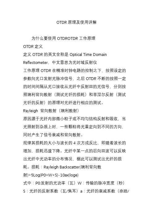
OTDR原理及使用详解为什么要使用OTDROTDR工作原理OTDR定义定义OTDR的英文全称是Optical Time Domain Reflectometer,中文意思为光时域反射仪工作原理OTDR在精准时钟电路的控制之下,按照设定的参数向光口发射光脉冲信号,之后OTDR不断的按照一定的时间间隔从光口接收从光纤中反射回的光信号,分别按照瑞利背向散射(测试光钎的损耗)和菲涅尔反射(测试光钎的反射)的原理对光纤进行相应的测试。
Rayleigh 背向散射(瑞利散射)原因源于光纤内部微小粒子或不均匀结构反射和吸收,当光照射到杂质上时,一些颗粒将光重定向到不同的方向,同时产生了信号衰减和背向散射。
规律其损耗的大小与波长的4次方成反比,即随着波长的增加,损耗迅速下降。
光纤中某一点的后向回波可以反映出光纤中光功率的分布情况,椐此可以测试出光纤的损耗。
损耗:Rayleigh Backscatter(瑞利背向散射)=5Log(P0×W×S)-10ax(loge)式中:P0:发射的光功率(瓦)W:传输的脉冲宽度(秒)S:光纤的反射系数(瓦/焦耳)a:光纤的衰减系数(奈踣/米)1奈踣=8.686dBx:光纤距离Fresnel 反射(非涅尔反射)原因当光到达折射率突变的位置(比如从玻璃到空气)时,很大一部分光被反射回去,产生Fresnel 反射,它可能比Rayleigh 背向散射强上千倍。
Fresnel 反射可通过OTDR 轨迹的尖峰来识别。
产生位置这样的反射例子有连接器、机械接头、光纤、光纤断裂或打开的连接器。
用途可检测链路沿线的物理事件。
OTDR 的结构OTDR测试过程第一步:清理光纤接口端面(法兰口)第二步:用光功率计测试链路是否有光(有强光会损坏OTDR)第三步:了解待测链路的状态,设置OTDR相应的参数第四步:OTDR测试及结果分析,保存距离测量原理如果折射率“n”设置不正确,所测出的距离也将是错误的!!损耗测量原理OTDR 产生返回光强度(背向散射加上反射)与光纤长度相关的光纤曲线熔接损耗是一种由于信号电平在接头点突然下降而造成的点损耗熔接时如果接点含有空气隙,就会产生具有反射的点损耗。
Palm Size Multimeter用户手册说明书

TMPalm Size MultimeterUser ManualPart Number: 72-13430, 72-13435 and 72-13440 TM1. OverviewThe new generation 72-13400 series products redefine the performance standards for entry-level digital multimeter. The innovative industrial design ensures the products have 2 meters impact resistance. The new LCD display layout provides a clear display for better user experience. The 72-13400 series ensure safe operation in CAT II 250 V environment.The special features of each model are as follows:72-13430: 2mF capacitance test function72-13435: Temperature test72-13440: NCV test2. Open Box InspectionOpen the package box and take out the device. Please check whether the following items are deficient or damaged and contact your supplier immediately if they are.User Manual 1 PcsTest Leads 1 PairProtective case 1 PcsK-type thermocouple 1 Pcs (72-13430 only)Warning:Please carefully read “Safe Operation Rule” before using the device.3. Safe Operation Rule1) Safety certificationThis device strictly follows the CE standards: EN 61010-1: 2010, EN61010-2-030: 2010, EN 61326: 2013, as well asCAT II: 250V, RoHS, pollution grade ll, and double insulation standards.2) Safety instructions and precautionsa. D o not use the device if the device or test leads appear damaged or if you suspect that the device is not operating property. Pay particular attention to the insulation layers.b. If the test leads are damaged, it must be replaced with one of the same type or the same electrical specification.c. When measuring, do not touch exposed wires, connectors, unused inputs, or the circuit being measured.d. W hen measuring the voltage higher than 60V DC or 30V ACrms, keep your fingers behind the finger guard on the test lead in order to prevent electric shock.e. If the range of the voltage to be measured is unknown, the maximum range should be selected and then gradually decreased.f. Never input voltage and current exceeding the value listed on the device.g. B efore switching ranges, make sure to disconnect the test leads with the circuit to be tested. It is strictly prohibited to switch the ranges during the measurement.h. D o not use or store the device in high temperature, high humidity, flammable, explosive or strong magnetic field environments.i. Do not change the internal circuit of the device in order to avoid the damage to the device and users.j. To avoid false reading, replace the battery when the battery indicator appears.k. Use dry cloth to clean the case, do not use detergent containing solvents TM4. Electrical Symbols5. Specification1. The maximum voltage between the input terminal and the ground: 250Vrms2. 10A terminal: Fuse 10A 250V Fast fuse Ø5 × 20mm3. mA/μA terminal: Fuse 200mA 250V Fast fuse Ø5 × 20mm4. Max. display 1999, over range display “OL”, update rate: 2~3 times/second5. Range select: Auto range 72-13430; Manual range 72-13430/435/4406. Backlight: manual on, auto shut off after 30 seconds.7. Polarity: “-” symbol displayin on screen represents negative polarity signal.8. Data hold function: symbol displays on screen when data hold function is activated.9. Low battery power: symbol displays on screen when battery power is low 10. Battery: AAA 1.5V × 211. O perating temperature: 0 ~ 40°C (32°F ~ 104°F)Storage temperature: -10°C ~ 50°C (14°F ~ 122°F)Relative humidity: 0°C ~ 30°C: %75% RH, 30°C to 40°C: %50% RH Operating altitude: 0 ~ 2000m12. Dimension: (134mm×77mm×47mm)13. Weight: about 206g (battery included)14. Electromagnetic compatibility:In fields with less the 1V/m radio frequency, the total accuracy = designated accuracy +5% of measurement range In fields with more than 1V/m radio frequency, the accuracy is not specified.6. Structure1.Display screen2.Function keys3.Functional dial4.10A input jack jack6.Remaining inputs jack(See Figure 1) TM7. Key Functions1) 72-13430:SEL/REL: press this key to switch between AC and DC modes for mV, I and REL positions.HOLD/: Press to enter or exit data hold mode. Long press over 2 seconds to turn on/off backlight.2) 72-13430/435/440:H OLD/SEL: Press to enter or exit data hold modeIn continuity/diode mode, press to cycle switch between the two modes: Press to turn on/off backlight.8. Operationsappears. Also pay special attention to the warning 1. AC/DC voltage measurement (see Figure 2b)1) Switch the dial to “V~” position.2) Insert the black test lead into the COM jack, the red test lead into the “VΩmA” jack. Connect test leads with the load in parallel.Notes:• D o not measure voltage over 250Vrms, or it may expose users to electric shock and damage the device. If the range of the voltage to be measured is unknown, select the maximum range and reduce accordingly.• Please pay extra attention when measuring high voltage in order to avoid electric shock.• Before using the device, it is suggested to measure a known voltage for verification.2. Resistance measurement (see Figure 2b)1) Switch the dial to “Ω” position.2) I nsert the black test lead into the COM jack, the red test lead into the “VΩmA” jack. Connect test leads with the resistor in parallel TMNotes:• Before measuring resistance, switch off the power supply of the circuit, and fully discharge of capacitors.• If the resistance when probes are shorted is more than 0.5Ω, please check if test leads are loosened or damaged.• If the resistor is open or over the range, the “OL” symbol will be displayed on the screen.• W hen measuring low resistance, the test leads will produce 0.1Ω ~ 0.2Ω measurement error. To obtain accurate measure-ment, the measured value should subtract the value displayed when two test leads are shorted.• W hen measuring high resistance above 1MΩ, it is normal to take a few seconds to steady the readings. In order to quickly obtain steady data, use short test wires to measure high resistance.3. Continuity measurement (see Figure 2b)1) Switch the dial to “” position.2) I nsert the black test lead into the COM jack, the red test lead into the “VΩmA” jack. Connect test leads with the points to be tested in parallel3) I f measured points’ resistance >51Ω, circuit is in open status.If measured points’ resistance ≤10Ω, circuit is in good conduction status, buzzer will go offNote:• Before measuring continuity, switch off all power supplies and fully discharge all capacitors.4. Diode measurement (see Figure 2b)2) I nsert the black test lead into the COM jack, the red test lead into the “VΩmA” jack. Connect test leads with the diode in parallel3) “OL” symbol appears when the diode is open or polarity is reversed. For silicon PN junction, normal value: 500 ~ 800mV (0.5 ~ 0.8V).Note:• Before measuring PN junction, switch off the power supply to the circuit, and fully discharge all capacitors5. Capacitance measurement (only for 72-13430, see Figure 2a)1) Switch the dial to capacitance test.2) I nsert the black test lead into the COM jack, the red test lead into the “VΩmA” jack. Connect test leads with the capacitor in parallel3) When there is no input, the device displays a fixed value (intrinsic capacitance).F or small capacitance measurement, to ensure measurement accuracy, the measured value must be subtracted from intrinsic capacitance.U sers can measure small capacity capacitors with relative measurement functions (REL) (the device will automatically subtract the intrinsic capacitance)Notes:• If the tested capacitor is shorted or its capacity is over the specified range “OL” symbol will be displayed on the screen.• When measuring large capacitors, it may take a few seconds to obtain steady readings• Before measuring capacitors (especially for high voltage capacitors), please fully discharge them.6. DC measurement (see Figure 3)1) Switch the dial to DC test.2) I nsert the black test lead into the COM jack, the red test lead into the “VΩmA” jack. Connect test leads with the tested circuit in series. TMNotes:• Before measuring, switch of the power supply of the circuit and carefully check the input terminal and range position.• If the range of the measured current is unknown, select the maximum range and then reduce accordingly.• Please replace the fuse with the same type.10A jack: Fuse 10A/250V Ø5mm×20mmVΩmA jack: Fuse 0.2A/250V Ø5mm×20mm• W hen measuring, please do not connect the test leads with any circuit in parallel. Otherwise there is a risk of damage to the device and human body.• I f the tested current is over 10A, each measurement time should be less than 10 seconds and the next test should be after15 minutes.7. AC measurement (only for 72-13430, see Figure 3)Similar to DC Measurement.Please refer to Section 6 “DC measurement (see Figure 3)”8. Temperature measurement (only for 72-13435, see Figure 5)1) Switch the dial to temperature test.2) I nsert K-thermocouple into the device and fix the temperature probe to the measured object. Read the value when it is stable.Notes:• Only K-thermocouple is applicable. The measured temperature should be less than 250°C/482°F (°F=°C×1.8+32) TM10. NCV measurement (only for 72-13440, see Figure 6)1) Switch the dial to NCV position2) P lace the device near the measured object. “-” symbol indicates the intensity of the electric field. More “-” and the higher the buzzer frequency, the higher the electric field intensity.3) Intensity of electric field.“EF” : 0 ~ 50mV“-” : 50 ~ 100mV“--” : 100 ~ 150mV“---” : 150 ~ 200mV“----” : >200mV11. Additional features• The device enters measurement status in 2 seconds after startup.• The device automatically shuts down if there is no operation for 15 minutes.you can wake up the device by pressing any key.To disable auto shutdown, switch the dial to OFF position, long press HOLD key and turn on the device.• When pressing any key or switching the dial, the buzzer will beep once.• Buzzer Notification1) Input voltage ^250V (AC/DC), buzzer will continuously beep indicating measure range is at limit2) Input current >10A (AC/DC), buzzer will continuously beep indicating measure range is at limit• 1 min before auto shutdown, 5 continuous beeps.Before shutdown, 1 long beeps.• Low power warnings:V oltage of the battery <2.5V, symbol appears and flashes for 3 seconds every 6 second period. During low power status, the device can still work. Voltage of the battery <2.2V, a solid symbol appears, the device cannot work. 9. Technical specification• A ccuracy: ±(% of reading + numerical value in least significant digit slot)1 year warranty TM• Ambient Temperature: 23°C ±5°C (73.4°F ±9°F)• Ambient humidity: %75% RHNotesTo ensure accuracy, operating temperature should be within 18°C ~ 28°C. Temperature Coefficient = 0.1*(Specified accuracy)/°C (<18°C or >28°C) 1. DC VoltageRange Part Number Resolution Accuracy200mV72-13430/13435/134400.1mV±(0.7% +3)2000mV1mV±(0.5% +2)20.00V0.01V±(0.7% +3)200.0V0.1V±(0.7% +3)250V1V±(0.7% +3)• Input impedance: about 10MΩ• R esults might be unstable at mV range when no load is connected. The value becomes stable once the load is connected.Least significant digit %±3• Max. input voltage: ±250V, when the voltage^ 610V, “OL” symbol appears.• Overload protection: 250Vrms (AC/DC)2. AC VoltageRange Part Number Resolution Accuracy200mV72-134300.1mV±(1% +2)2V0.001V±(0.7% +3) 20V0.01V±(1% +2)200V72-13430/13435/134400.1V±(1.2% +3)250V1V±(1.2% +3)• Input impedance: about 10MΩ• Frequency response: 40Hz ~ 400Hz, sine wave RMS (average response).• Max. input voltage: ±250V, when the voltage 610V, “OL” symbol appears.• Overload protection: 250Vrms (AC/DC)3. ResistanceRange Part Number Resolution Accuracy200Ω72-13430/13435/134400.1Ω±(1% +2)2000Ω1Ω±(0.8% +2) 20kΩ0.01kΩ±(0.8% +2) 200kΩ0.1kΩ±(0.8% +2) 20mΩ0.01MΩ±(1.2% +3) 200mΩ72-13430/134400.1MΩ±(5% +10) TM• Measurement result = reading of resistor - reading of shorted test leads • Overload protection: 250Vrms (AC/DC)4. Continuity, diode• Overload protection: 250Vrms (AC/DC)5. Capacitance (only for 72-13430)Range Resolution Accuracy2nF0.001nF Under REL mode ±(5% +5)20nF0.01nF±(4% +8)200nF0.1nF±(4% +8)2μF0.001μF±(4% +8)20μF0.01μF±(4% +8)200μF0.1μF±(4% +8)2mF0.001mF±(10)• Overload protection: 250Vrms (AC/DC)• Tested capacitance %200nF, adapt REL mode.6. Temperature (only for 72-13435)Range Resolution Accuracy°C-40°C ~ 1000°C-40 ~ 40°C1°C±4°C >40°C ~ 500°C±(1% +4) >500°C ~ 1000°C±(2% +4)°F-40°F ~ 1832°F-40°F ~ 104°F1°F±5°F>104°F ~ 932°F±(1.5% +5) >932°F ~ 1832°F±(2.5% +5)• Overload protection: 250Vrms (AC/DC)• K thermocouple is only applicable for temperature less than 250°C/482°F. TM7. DC currentRange Part Number Resolution Accuracy 200μA72-134300.1μA±(1% +2) 2000μA72-13430/13435/134401μA±(1% +2) 20mA72-13430/13435/134400.01mA±(1% +2) 200mA72-13430/13435/134400.1mA±(1% +2) 2A72-134300.001A±(1.2% +5) 10A72-13430/13435/134400.01A±(1.2% +5)• Input current> 10A, “OL” symbol appears and buzzer beeps • Overload protection250VrmsμA mA range: F1 Fuse 0.2A/250V Ø5×20mm10A range: F2 Fuse 10A/250V Ø5×20mm8. AC current (only for 72-13430)Range Part Number Resolution Accuracy200μA72-134300.1μA±(1.2% +3)2000μA1μA±(1.2% +3)20mA0.01mA±(1.2% +3)200mA0.1mA±(1.2% +3)2A0.001A±(1.5% +5)10A0.01A±(1.5% +5)• Frequency response: 40 - 400Hz• Accuracy guarantee range: 5 - 100% of the range, shorted circuit allows least significant digit %2• Input current >10.1A, “OL” symbol appears with beeps• Overload protection250VrmsμA mA range: F1 Fuse 0.2A/250V Ø5×20mm10A range: F2 Fuse 10A/250V Ø5×20mm10. MaintenanceWarning: Before opening the rear cover, switch of the power supply (remove test leads from the input terminal and the circuit).1. General maintenance1) Clean the case with a damp cloth and detergent. Do not use abradants or solvents2) If there is any malfunction, stop using the device and send it to maintenance.3) The maintenance and service must be conducted by qualified professionals or designated departments.2. Replacements (see Figure 7a, Figure 7b)Battery replacement:To avoid false reading, replace the battery when the battery indicator appears.Battery specification: AAA 1.5V × 21) Switch the dial to “OFF” position and remove the test leads from the input terminal. TMTM Page <11>V1.004/03/192) T ake off the protective case. Loosen the screw on battery cover, remove the cover to replace the battery. Please identifythe positive and negative pole.Fuse replacement:1) Switch the dial to “OFF” position and remove the test leads from the input terminal2) Loosen the both screws on the rear cover, then remove the rear cover to replace the fuseF use specificationF1 Fuse 0.2A/250V Ø5×20mm ceramic tubeF2 Fuse 10A/250V Ø5×20mm ceramic tubeImportant Notice : This data sheet and its contents (the “Information”) belong to the members of the Premier Farnell group of companies (the “Group”) or are licensed to it. No licence is granted for the use of it other than for information purposes in connection with the products to which it relates. No licence of any intellectual property rights is granted. The Information is subject to change without notice and replaces all data sheets previously supplied. The Information supplied is believed to be accurate but the Group assumes no responsibility for its accuracy or completeness, any error in or omission from it or for any use made of it. Users of this data sheet should check for themselves the Information and the suitability of the products for their purpose and not make any assumptions based on information included or omitted. Liability for loss or damage resulting from any reliance on the Information or use of it (including liability resulting from negligence or where the Group was aware of the possibility of such loss or damage arising) is excluded. This will not operate to limit or restrict the Group’s liability for death or personal injury resulting from its negligence. Tenma is the registered trademark of the Group. © Premier Farnell Limited 2016.。
信维科技palmOTDR使用手册

palmOTDR 系列 掌上型光时域反射仪世界上最小的一款高性能OTDR◆ 全面光纤应用,理想的LAN/WAN/FTTx 认证和故障解决工具:单模:1310/1490/1550, 1625/1650nm (带滤波器),动态范围最高50dB ;多模:850/1300nm ,21/24dB◆ 故障定位,光纤长度/损耗测试,可探测连接器/熔接点/分路器/宏弯/光纤末端等事件◆ 内置PON 光功率计,可测量三重播放业务信号(1310/1490/1550nm)◆ 可选配稳定光源、单模/多模光功率计和可视故障定位仪 ◆ FTTx 在线测试/可穿通1:64分路器测试(1625/1650nm 波长带滤波器) ◆ 可识别分路器和光纤末端◆ 多种测试方式可选:全自动/手动/平均/实时 ◆ 具有通过/失败评估以及光回损测试功能 ◆ 快速启动<5 秒◆ 高效友好的人机界面,掌上型轻量化设计(仅重1kg)◆ 独特的热键设计:目前世界上操作最简单的OTDR ,开机单键即测 ◆ 1000条迹线存储 ◆ Bellcore 文件格式(.sor) ◆ 上位机软件可批处理数据 ◆ USB/RS232数据接口,免驱动◆ 优化的供电设计:内置充电电池一次充电可支持8小时连续测量或者20小时待机状态 ◆ 防尘、防震设计(通过2米跌落试验) ◆ 通过CE 、FCC 、FDA 等权威认证开机启动时间小于5秒palmOTDR 系列从开启电源到进入界面并启动测试只需要不到5秒时间,用户无需等待。
信维科技palmOTDR 系列掌上型光时域反射仪提供了丰富的测试功能,可灵活配置850/1300/1310/1490/1550/1625/1650nm 等波长OTDR (单波长/双波长/三波长组合)、1310/1490/1550nm PON 光功率计、稳定光源和可视故障定位仪,以实现最高的应用价值。
palmOTDR 的工作波长涵盖了常规的端到端光纤测试(1310/1550nm ),局域网测试(850/1300nm ),FTTx 建设期光纤链路验证(1490nm )以及PON 网络在线故障定位(1625/1650nm )等。
PCI-R5001 系列人脸识别终端 安装使用手册说明书

安装使用手册声明非常感谢您购买我公司的产品,如果您有什么疑问或需要请随时联系我们。
◼我们已尽量保证文档内容的完整性与准确性,但也不免出现技术上不准确、与产品功能及操作不相符或印刷错误等情况,如有任何疑问或争议,请以我司最终解释为准。
◼产品和文档将实时进行更新,恕不另行通知。
◼本文档中内容仅为用户提供参考指导作用,请以实际内容为准。
历史版本目录产品介绍 (1)产品简介 (1)产品外观 (2)硬件接口 (3)网络架构 (3)安装说明 (4)壁挂安装方式 (4)安装示意图 (4)详细安装步骤 (5)闸机安装方式 (6)安装示意图 (6)详细安装步骤 (7)设备接线指引 (8)设备接线(带门禁扩展模块) (8)使用操作 (9)设备启动 (9)设置日期时间 (9)主页面 (10)刷脸模式 (11)刷卡模式 (13)刷卡加人脸模式 (13)刷卡加密码模式 (15)密码开门模式 (16)远程开门模式 (17)识别距离提示 (18)门禁常开常闭提示 (19)消防联动提示 (20)进入配置界面 (21)人员库 (22)本地人员库 (23)联网人员库 (24)识别记录 (24)本地记录 (25)联网记录 (25)记录导出 (26)本地登记 (27)人员更新 (28)算法设置 (29)开启活体 (30)1:N人脸识别阈值 (30)识别距离 (30)帽子检测 (31)注册参数 (32)核验模式 (33)设备接口 (35)韦根协议 (36)开关量信号 (37)RS232串口 (37)设备IO输入 (39)网络配置 (39)通用设置 (41)隐私显示 (42)日期时间 (42)门禁设置 (43)显示设置 (45)语音设置 (46)设备重启 (47)管理员密码 (48)重置 (49)关于设备 (50)登记人脸标准规范 (51)常见问题处理 (54)注意事项 (56)产品介绍产品简介PCI-R5001是佳都科技研发的新一代5英寸屏幕的人脸智能终端产品,采用国际一流工业设计标准,追求极致品质,具有人脸识别速度快、精度高、可防伪、扩展灵活等特点。
Oracle Field Service Palm 设备概念与操作指南说明书
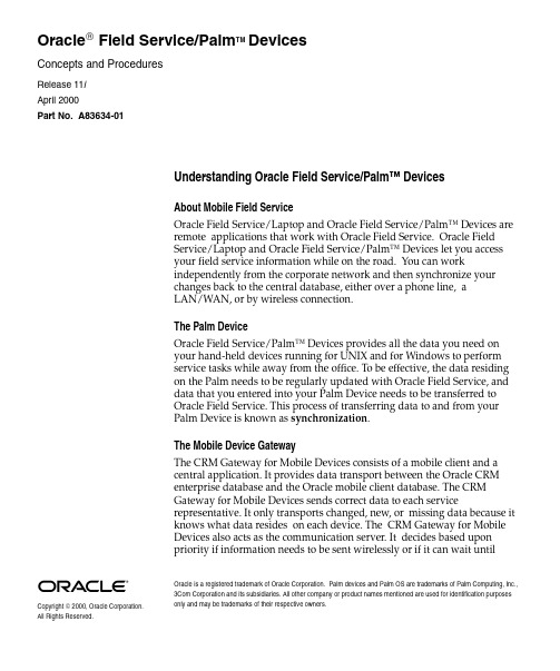
Copyright 2000, Oracle Corporation. All Rights Reserved.Oracle is a registered trademark of Oracle Corporation. Palm devices and Palm OS are trademarks of Palm Computing, Inc., 3Com Corporation and its subsidiaries. All other company or product names mentioned are used for identification purposes only and may be trademarks of their respective owners.Oracle Field Service/Palm TM DevicesConcepts and ProceduresRelease 11iApril 2000Part No. A83634-01Understanding Oracle Field Service/Palm™ DevicesAbout Mobile Field ServiceOracle Field Service/Laptop and Oracle Field Service/Palm™ Devices areremote applications that work with Oracle Field Service. Oracle FieldService/Laptop and Oracle Field Service/Palm™ Devices let you accessyour field service information while on the road. You can workindependently from the corporate network and then synchronize yourchanges back to the central database, either over a phone line, aLAN/WAN, or by wireless connection.The Palm DeviceOracle Field Service/Palm™ Devices provides all the data you need onyour hand-held devices running for UNIX and for Windows to performservice tasks while away from the office. To be effective, the data residingon the Palm needs to be regularly updated with Oracle Field Service, anddata that you entered into your Palm Device needs to be transferred toOracle Field Service. This process of transferring data to and from yourPalm Device is known as synchronization.The Mobile Device GatewayThe CRM Gateway for Mobile Devices consists of a mobile client and acentral application. It provides data transport between the Oracle CRMenterprise database and the Oracle mobile client database. The CRMGateway for Mobile Devices sends correct data to each servicerepresentative. It only transports changed, new, or missing data because itknows what data resides on each device. The CRM Gateway for MobileDevices also acts as the communication server. It decides based uponpriority if information needs to be sent wirelessly or if it can wait untilmanual synchronization. This is done to save money, because wireless communication is very expensive.Palm Device Application FlowThe figure shows the relationship between the different screens in the Oracle Field Service Palm application.I When new mail messages arrive, the mail notification icon is up. It isdown when all the mail is read. Reading and sending mail does not disturb the working process.I The shortcut menu is disabled but shortcuts are available on your PalmDevice when using the Oracle Field Service/Palm™ Devicesapplication. A description of the shortcuts can be found in the HelpUser info screen.I Data beaming is disabled when using the Oracle Field Service/Palm™Devices application.The AgendaThe Agenda screen displays all service tasks for the current day. You can view your agenda when you start the Field Service/Palm™Devices application the first time. You can see at a glance the schedule for the day and the status of the tasks dispatched to you. Start your working day by turning the ignition key to record your working hours. Perform your tasks from the top down in order to not to disturb the service schedule.The Agenda screen displays the following:Refer to this table for an explanation on the items displayed in the Agenda screen:Customer Info featuresThe Customer Info screen provides detailed information on the customer for the task selected. You can view the following:Item DescriptionT ask lineThe task line provides the following information:I Severity, is set to 1, 2 or 3 (1=high).IStatus, the field is empty when the task is still open,displays an ’arrow ’ when working, a ’V’ when the task is completed, a ’!’ when the task was interrupted, and an ’X ’ when it was canceled.I Start time the planner scheduled the task to start. I Service Request reference number.IA short description of the task.Note Tapping the note icon displays additional information related to the task when not dotted, and is used to enter a note.Antenna The antenna indicates if mobile communication is possible or not. It will be hanging down when it is not possible. Clock The clock displays the time.Ignition key The ignition key is turned on by tapping it at the start of a working day, and it is turned off at the end of the day. Date The date can be changed by tapping it. The agenda shows the tasks for the selected date.Day Day can be changed by tapping it, the agenda shows the tasks for the selected day.T ripThe on-duty time is displayed as a Trip with a start and end time. It appears when you tap the ignition key. Tapping it shows you a list of worked hours.Mailbox Mailbox shows whether you have new or unread mail and can be accessed by tapping it.InformationTapping displays information about the FieldService/Palm ™Devices application and some guidelines on how to use it.Item DescriptionCust nr Reference number related to the Customers name.AddressCustomer address.Understanding TasksA task is considered to be a unit of work. Tasks are created in relation to service requests. Service requests are created in the back office. A planning of all tasks is made and a schedule is send to you by the dispatcher.Information regarding the work requiered for the task is send along with this schedule. This information needs to be updated and checked. Use the task screen to view and update the following:You also need to report on labor time, materials used, and expenses made. Use the Debrief screen to do so, for more information see Reporting on a Task .Address 2Additional address field. City City name.Zip Zip or Postal code.State State name.Phone Phone number of contact at customer.Service req Service request reference number.Service reqNoteNote displays dispatcher information and is used to add notes.Item DescriptionT ask Nr Task reference number.T ask Description of work that needs to be done.StatusUpdate status to enable the dispatcher to monitor progress on your working day. Possible statuses are user definable. Priority Priority given to task.Product Product name is displayed. Open note to view detailed information on product and installed base.Serial nr Serial number of product is shown.ProblemDescription of problem.Note:To update on problem description add aService req Note.SolutionDescription of solution.Note:To update on solution description add aService req Note.Item DescriptionCountersA counter is an entity that records usage of a product. A lot of machines you are servicing contain one or multiple counters for all kinds of purposes. A selection of counters with their last reading for the machine you areservicing have been sent along with the task. Update or add a value for the counter after selecting it. Use Miscellaneous Reading to perform a test and Reset Counter to reset the counter, for example after a replacement of the counter.A counter reading consists of the following:I Name I Time stamp I ValueIUnit of measureReporting on a TaskUse the Debrief screen to view, add, and update on labor time, materials used, and expenses made for a specific task. This information needs to be accurate because after the Palm device is synchronized with the Field Service database, the information is used to generate an invoice.Reporting on LaborDefine the different types of labor you performed to complete a task. Reporting on labor is done by selecting a labor type and associating an amount of labor time, and an action. In the Set Labor screen define the following:Reporting on MaterialReport on all the materials involved during the completion of the task. For each material report on the amount used and kind of action performed. After selecting a material in the Set Material screen define the following:Item DescriptionStart Select a start time by using the hours and minutes bars on the right.End Select an end time by using the hours and minutes bars on the right.ActionSet action to labor.Reporting on ExpensesDefine the different types of expenses you made to complete a task.Reporting on expenses is done by selecting an expense type, associating an amount of the expense type, and an amount of money involved. In the Set Expense screen define the following:Item DescriptionRevision The revision number is populated automatically.Lotnumber The lotnumber is populated automatically.Serial Nr If a serial number applies for the selected material the field is shown, the serial number should be entered. Qty Enter the quantity for the selected material.Uom Associate an unit of measurement for the quantity entered.ActionAssociate an action for the material you are reporting on.Item DescriptionQty Enter the quantity for the selected expense.Uom Associate an unit of measurement for the quantity entered.Action Associate an action for the expense you are reporting on.Amount Enter the amount of money for the currency selected.CurrencySelect the currency used.Using Oracle Field Service/Palm™ DevicesSynchronizing the Palm DeviceBefore you start the Field Service/Palm™Devices application, you must synchronize to obtain your service tasks from the Oracle Field Service database. You must frequently synchronize your Palm Device with Oracle Field Service to make your updated information available to others and to keep your Palm up to date. Use this procedure to manually synchronize your Palm Device service data with Oracle Field Service through the CRM Gateway for Mobile Devices.PrerequisitesEach Palm user must be asigned an account on the Mobile Device Gateway before data can be synchronized.For more information, refer to the CRM Gateway for Mobile Devices online documentation. Also see About Mobile Field Service.Steps1.Tap the Applications icon on the Palm Device to display theapplication picker.2.Tap the OL Sync icon from the application launcher.3.Tap Sync.Using the Oracle Field Service/Palm™ DevicesThere are some general guidelines on how to handle the service tasks with your Palm Device.PrerequisitesNoneSteps1.Tap the Applications icon on the Palm Device to display theapplication picker.2.Tap the OMFS Palm icon from the application launcher. A startupscreen with the service representatives name is displayed briefly. Then the Agenda screen appears.3.Tap the I gnition key. Your working hours are recorded and stored. Atrip start time entry appears at the top of the tasks.4.Tap the first open task line. The Customer Info screen appears. Viewdispatcher notes when available or add them at Service req.5.Tap Task to open the Task screen.I Update the status of the task by selecting an option from thedropdown list.I View details of the component you are working on at Product.I View problem and solution.6.Tap Count to open the Counter screen.I Update the reading by tapping it.I Add a reading for a counter by tapping Add.7.Tap Debrief to open the Debrief screen. Report on labor time, materialsused, and your expenses as necessary.8.Tap Task to return to the Task screen. Update the status of the task byselecting an option from the dropdown list.9.Return to the Agenda by tapping Agenda. Open another task ifnecessary10.At the end of the day, tap the Ignition key. The trip end time isautomatically filled in.。
- 1、下载文档前请自行甄别文档内容的完整性,平台不提供额外的编辑、内容补充、找答案等附加服务。
- 2、"仅部分预览"的文档,不可在线预览部分如存在完整性等问题,可反馈申请退款(可完整预览的文档不适用该条件!)。
- 3、如文档侵犯您的权益,请联系客服反馈,我们会尽快为您处理(人工客服工作时间:9:00-18:30)。
不要在易爆环境中操作
不要在存在可燃性气体或烟雾时使用仪器。
不要卸下仪器外套
操作人员切勿卸下仪器外罩。更换部件和内部调整只能由合格的维修人员进行。
本手册的安全术语
警告符号表示存在危险。它提请用户对某一过程、操作方法或类
似情况的注意。如果不能正确操作或遵守规则,指出的警告条件之前,不要继续下一
Shineway Technologies, Inc.
-i-
palmOTDR 系列光时域反射仪用户手册
安全须知
在本仪器工作的各个阶段,都必须采取以下一般性安全措施。不采取这些安全措 施或不遵从本手册其他地方所述的特定警告,将会违反仪器设计、制造和使用的安全 标准。信维科技对于客户违反这些要求所造成的后果不承担任何责任。
2、基本操作 ........................................................................................................................... 3
2.1 前言...............................................................................................................................3 2.2 仪表接口说明 ...............................................................................................................3 2.3 充电电池的使用 ...........................................................................................................4 2.4 功能键说明 ...................................................................................................................6
提示符号给出有助于仪表使用和维护的信息。
警告事项
¾ 光时域反射仪是激光设备,用户应始终避免直视激光输出口。用户更不能用 显微镜、放大镜等设备观察光源输出口,激光束的能量聚到视网膜上,会造 成眼睛的永久伤害。
¾ 用 palmOTDR 测量光纤时,被测光纤中一定不能有工作光,否则会导致测量结 果不准确,严重时会对仪表造成永久性损坏。
保证
本文档所含内容如有修改,恕不另告。信维科技公司对本资料不作任何保证,包 括但不限于为特定目的的适销性和适应性所作的暗示保证。对其中包含的错误或由供 给使用本资料或由版本资料的实用性而引起的偶然或继发的损失,信维科技公司不承 担任何责任。
电池为易耗部件,不受 palmOTDR 保证的制约。
出版记录
3.4 palmOTDR 轨迹屏幕 ...................................................................................................9 3.4.1 palmOTDR 轨迹显示窗.......................................................................................9 3.4.2 palmOTDR 信息窗: ...........................................................................................10 3.4.2.1 轨迹测量参数 ...............................................................................................10 3.4.2.2 事件列表 ....................................................................................................... 11 3.4.2.3 A/B 标尺的信息............................................................................................ 11 3.4.2.4 光纤链的信息 ...............................................................................................12 3.4.3 palmOTDR 工具栏窗.........................................................................................12 3.4.3.1 palmOTDR 工具栏图标 ...............................................................................12 3.4.3.2 palmOTDR 参数设置操作 ...........................................................................13 3.4.3.2.1 测量参数定义 ........................................................................................14
总则
本产品为 3 类安全仪器。如不按照操作手册使用本产品,其保护功能可能会失效。
工作环境
本仪器(不带 AC 适配器)为Ⅱ类安全设备,适合在污染度为 2 级的室外环境中使 用。最大相对湿度 95%,海拔高度达 2000 米。有关 AC 电源电压要求和操作环境温度, 请参阅技术指标表。
接通电源前
确认产品设置为匹配的可用电源电压、安装了合适的熔断器并采取了所有的安全 措施。
本手册的创作、出版及更新记录如下: 第一版……2004 年 4 月 第二版……2005 年 6 月 第三版……2006 年 1 月 第四版……2007 年 1 月 ISO9001 认证 通过改进生产过程控制,使产品符合 ISO9001 国际质量体系标准,是我们不断提 高用户满意度这一目标的组成部分。
3.3 palmOTDR 的测量用途 ...............................................................................................9 3.3.1 palmOTDR 测量内容...........................................................................................9 3.3.2 palmOTDR 轨迹分析...........................................................................................9
3、palmOTDR 基础知识......................................................................................................7
3.1 palmOTDR 的原理 .......................................................................................................7 3.2 事件基本定义及分类 ..................................................................................................7
步。
Shineway Technologies, Inc.
- ii -
palmOTDR 系列光时域反射仪用户手册
小心符号表示存在危险。它提请用户对某一过程、操作方法或类 似情况的注意。如果不能正确操作或遵守规则,则可能对仪器造 成部分或全部损坏或损毁。在完全理解和满足所指出的小心条件 之前,不要继续下一步。
外部电源:本公司所有手持仪表均支持外部电源,电源要求 DC 13.8V/1.2A。 注意激光辐射:在光纤系统的测量过程中,要注意避免眼睛对着开路的光纤、光 纤接口、光纤连接点和其他光源等,否则会使眼睛接触到正在传输的激光而受到伤害。 ¾ 当光时域反射仪工作时,眼睛不要直视激光输出口。 ¾ 光时域反射仪使用完毕,请把光口防尘帽盖上。 ¾ 不要直视正在测试中的光纤未连接端。如果可能的话,让光纤的未连接端指 向一个无反射的物体上。
3.2.1 事件 ........................................................................................................................7 3.2.1.1 反射事件 .........................................................................................................7 3.2.1.2 非反射事件 .....................................................................................................8 3.2.1.3 检测事件 .........................................................................................................8