惠普HP_CQ32_拆机_图文教程
部分惠普打印机一体机拆机方法

部分惠普打印机/一体机拆机方法一、2128(1)将四颗螺丝拧开,如图1所示。
将整个机器上盖拆下。
拆下上盖时应注意慢抬,以免损伤机器内的控制面板及扫描组件与主板的连接线,如图2所示。
图1图2(2)拆除图3上所示的六颗螺丝,便可以拆下笔架,拆除时应注意笔架与主板的连接线。
如图3所示。
图3(3)将后挡纸板取下,拆下最右边的清洁单元,然后拧下中间的螺丝和左边的卡子,便可以拆除整个进纸单元。
如图4所示。
图4(4)拧下螺丝,拆除马达,便可以取下主板。
如图5所示。
图5(5)取下整个玻璃板,便可以拆下扫描头组件,取下玻璃板时应注意控制面板下的数据线。
如图6所示。
图6二、3508/3608(1)将图1所示的控制面板按图2所示的黄色箭头方向打开。
图1图2(2)将图3中红圈中的螺丝拧下来,取下话筒下边的盖子。
图3 (3)拧下图4中2个红圈处的螺丝。
图4 (4)将图5中3个孔处的螺丝拧下来。
图5(5)将图6中红圈处的螺丝拧下来,并把后挡板按图6中黄色箭头的方向取下来,就可以拿下中间的壳了。
图6(6)拔掉图7、图8中所示的各连接到板上的数据线。
图6图7(7)把固定板的螺丝拧下来,就可以把板取下来了。
如图8红圈所示。
图8(8)将图9红圈处的铁板取下来,取下时要小心两边的卡子。
图9(9)将扫描组件取下来的时候注意图10中两个红圈处的卡子。
图10 (10)然后即可拆卸机器。
如图11、图12所示。
图11图12打印机下半部分的拆卸方法参见DJ3000系列。
如图13所示。
图13三、5328(1)取下机器的白色外盖。
如图1、图2所示。
图1将这个白色的盖取下来图2(2)将控制面板的外盖取下来。
如图3、图4所示。
图3图4(3)将图5中红圈处的2个小堵塞物拿下来,这里有2颗螺丝。
图5(4)将2颗螺丝拧下来,就可以取下控制面板了。
如图6所示。
图6(5)将固定侧盖的螺丝拧下来。
如图7所示。
图7(6)取下侧盖时注意机器低部的卡子。
如图8所示。
图8(7)取下白色的盖子。
hp显示器怎么拆开

hp显示器怎么拆开显示器(display)通常也被称为监视器。
显示器是属于电脑的I/O 设备,即输入输出设备。
它是一种将一定的电子文件通过特定的传输设备显示到屏幕上再反射到人眼的显示工具。
下面是店铺带来的关于hp显示器怎么拆开的内容,欢迎阅读!hp显示器怎么拆开?方法/步骤1把液晶显器放平,再拿双手扣住液晶的外框,用力往上扣,扣松。
2扣开以后,再扣另一个角,扣松,不要着急,力度适中。
3再把扣松的地方拉开。
4延边一路扣过去,把扣开的都拉开。
5拿掉外框。
就可以看到液晶显示器的控制面板了。
6拆液晶显示器里面的部件,只需要把看到的螺丝下下来就可以拆开了。
7安装面板的时候注意。
手要顶住按键。
再压下去。
8再把四周的边对好,再用手压紧就可以了。
相关阅读推荐:21世纪惠普发展历程2001年9月4日,惠普以价值250亿美元的股票收购对手康柏电脑公司。
2002年5月,两公司合并完成。
2003年,公司的市值达到80.28亿美元,从而在全球基础架构服务市场中占有6.2%的份额。
2006年第四季度,超越戴尔(Dell)成为全球第一大PC厂商。
2008年,财政营收额突破1000亿美元截止2012年初,惠普一直保持全球第一大PC厂商地位。
2011年2月10日,惠普公司新品发布会于美国旧金山召开。
在这场以“Think Beyond”为主题的新品发布会中,惠普公司正式公布了全新版本的webOS系统、HP Veer、HP Pre 3两款智能手机以及惠普TouchPad平板电脑。
2013年10月30日,发布了配置Calexda ARM架构芯片的Moonshot服务器。
2012年至2017年亚太地区整体印刷设备预计将实现2.5%的年增长率,对数字印刷设备的需求较去年同期将显著提高,实现每年9.4%的增长,而传统打印设备预计将停止增长。
HPCompaq笔记本V3000拆机图
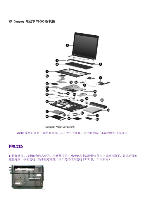
HP Compaq 笔记本V3000拆机图V3000系列可谓是一款经典系列,具有大方的外观、适中的价格、不错的性价比等优点,拆机过程:1.拆卸键盘。
将电池仓内高处的三个螺丝拧下,掀起键盘上部轻轻向前向上提就可取下,注意后面有键盘连线,拔去连线(新手注意此处“拔”是指打开连线卡口后拔,后面相同)。
2.拆卸无线网卡。
打开无线网卡后盖,拔下天线(向上一提就可以),卸下无线网卡,这一步是为了后面拆卸主机的上盖3.卸下光驱。
卸下固定光驱的螺丝,用曲别针一端捅下光驱面板的小孔,光驱即可弹出,向外一拉光驱就拆下了。
4.卸下硬盘。
这步简单,省略~5.卸下后盖螺丝。
螺丝很多,包括10个较大螺丝(固定光驱的那个除外)、硬盘仓内3个、光驱仓边2个、电池仓低处3个。
建议将螺丝归类放置并注明位置6.拆卸开关面板。
这个面板在第一次拆卸时可能比较紧,要用力适中,可能左右松紧不一样,我的左边好卸些,都是塑料卡口,先抬起两边再分中间部分。
卡槽我标了两个,还有中间的小卡片没标,拆时注意一下,不能用蛮力。
拆下后反过来,将开关与控制条连线拔掉就可卸下了。
7.将本本放好,卸下键盘位置右上方的1个螺丝。
8.取下液晶屏。
拔去液晶屏连线,抽出无线网卡天线,若有内置话筒就拔去话筒连线,我的3240没有内置,将液晶屏数据线排线揭起,卸下液晶屏支架的5个螺丝(左3右2),卸下液晶屏。
9.这样液晶屏与主机就分离了。
10.拆卸主机上盖。
拔出触摸板连接,用废银行卡或别的卡片插入缝隙中两侧滑动就可分开上盖。
11.拔出喇叭连线,卸下左喇叭左方和上方的2个螺丝,取下左喇叭,连同连线放到旁边。
拔去与主板连接的各个连线。
12.卸下无线网卡开关及耳麦插孔,这样方便卸主板。
13.卸下主板右下侧的唯一1个螺丝,这时就可取下主板。
14.卸下散热器(共5个螺丝),拔下主板风扇连线,卸下风扇,进行大清扫。
15.清扫完毕,看着一个完整的本本被拆的七零八落,是不是很有成就感~按照刚才的步骤再倒着装上去,这时仍然要仔细,各个线都要连好,要不少连根线还要重新拆开,太多螺丝了~。
惠普笔记本拆机图解教程

惠普笔记本拆机图解教程1.备好螺丝刀,拆下笔记本电池。
2.拆下图示中的若干螺丝。
3.图示中的这颗螺丝是内存盖的,拧不出来,拧松即可拆下内存盖。
4.拧松图示中的螺丝。
硬盘盖合的比较紧,如图,将银行卡插入一侧,启开卡扣,即可轻易撬开。
5.拧下白色图示中的螺丝,轻揭红色图示中的卡扣,往外轻抽无线网卡,即可拆下。
内存条上面有一层纸状黑色塑料遮挡物,轻揭开就可见到内存条。
6.如图所示,将手指插入硬盘一侧,轻轻往外撬,可以轻易拿出硬盘。
红色图示中的是硬盘接口,一手拿住硬盘,一手捏住接口往外抽,即可轻易抽出。
切记:不要捏住接线来抽。
7.拆下图示中的若干螺丝。
受图片质量所限,可能有误标或漏标之处,请自行再细查。
8.接下来拆键盘,有两种方法。
1.如第一幅图所示,将螺丝刀插入键盘与机身缝隙中,往外撬,启开卡扣。
然后,如第二幅图所示,插入废弃银行卡,往左划,揭开其余卡扣,即可拆下键盘。
这个方法会在机身留下划痕,破坏整体美观。
2.如第三幅图所示,双手按住键盘,往下扒,弄开卡扣,拆下键盘。
9.拆下键盘不要急着往外拿,往上揭开,可以看到下面的接线。
将图示中黑色的小盖子往上揭,就可抽出排线,彻底取下键盘。
不必担心接口拆下安不上,把排线往接口插进去,合上盖子即可。
10.拆下图示中的螺丝与排线接口。
排线接口拆法与上相同。
11.拆机身盖。
用手别开一个缝隙,趁机插入废弃银行卡,往左右划开卡扣,揭开盖子。
如遇特别紧的地方,请查看是否有螺丝未拧。
12. 1.光驱是可以直接抽出来。
2.方形图示中本来有一个卡扣固定光驱接口,我嫌之无用,拆下以后就没有再装上,图中没有。
3.拆下各椭圆图示中的螺丝和接口。
显示器的排线接口用一块透明胶带固定,揭开以后,再贴粘性不佳,最好自备绝缘胶。
13.从右往左,揭起主板,将之取下来。
下图为主板正反面。
14.注意图示中的数字,按照顺序将螺丝拧松。
揭起散热器,拆下风扇排线接口(双色图示),彻底取下散热器。
15.图一为散热器背面图,除尘清灰处理它就行。
惠普笔记本电脑怎么样拆机
惠普笔记本电脑怎么样拆机
惠普笔记本电脑怎么样拆机
01先仔细观察笔记本上的'螺丝是如何分布的,方便拆机的时候操作。
02所有螺丝都必须拆下来,先将光驱的螺丝拆下来然后拿掉光驱,再拆接下来其他的螺丝。
03接着就可以将机器从键盘面拆开了,一定要小心且缓慢注意键盘下方的线路,不要损坏了。
04一定得按照步骤来,每个线都有卡扣,先板起来再拔线。
05最后就拆开了,硬盘在右边内存条在主板下面。
特别提示
一定要保管好拆除下来的螺丝钉。
惠普cq42拆机
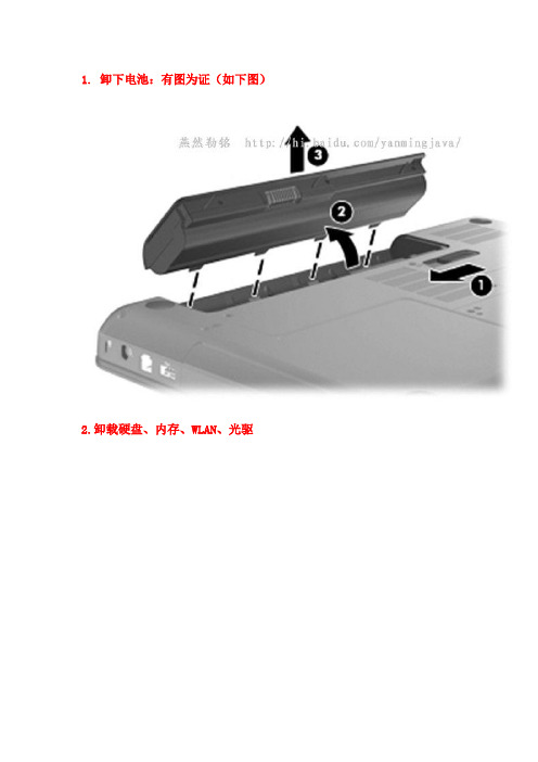
1. 卸下电池:有图为证(如下图)2.卸载硬盘、内存、WLAN、光驱拧开螺丝,揭开硬盘盖(如下图)拧开固定硬盘螺丝,抓住聚酯薄膜标签往上方拉,断开硬盘电缆,提出硬盘。
(如下图)拧开固定光驱螺丝,将光驱提出来(如下图)拧开螺丝,揭开内存盖(如下图)断开WLAN电缆,拧开螺丝,取出WLAN模块(如下图)取出内存条(如下图)3.卸载键盘拧开固定键盘螺丝(如下图)抬起键盘①,直到一定角度,滑动键盘②(如下图)断开ZIF连接器,取下键盘(如下图)4.卸载顶盖拧开固定顶盖的螺丝(如下图)断开以下ZIF连接:触摸板、扬声器、电源开关(如下图)拧开固定螺丝,抬起顶盖,直到一定角度,滑动顶盖,取下顶盖(如下图)5.卸载扬声器、电源开关按钮板、Modem模块、蓝牙模块、USB板、电源控制器卸载扬声器(如下图)卸载电源开关按钮板(如下图)卸载Modem模块(如下图)卸载蓝牙模块(如下图)卸载USB板(如下图)卸载电源控制器(如下图)6.卸载显示器断开以下与主板连接:无线WLAN电缆,显示器,麦克风,摄像头(如下图)拧开固定显示器螺丝,取下显示器(如下图)7.卸载主板拧开固定主板螺丝(如下图)断开光驱电缆,抬起右侧,取出主板(如下图)8.卸载RJ11、光驱连接器、RTC电池卸载RJ11连接器及电缆(如下图)拧开固定光驱连接器螺丝,取下光驱连接器及电缆(如下图)取下RTC电池(如下图)9.卸载风扇/散热片装置松开固定风扇/散热片装置到系统板螺丝,取下风扇/散热片装置(如下图)10.卸下处理器:使用平头螺丝刀把处理器锁定螺钉,按逆时针拧直到听到咔嗒声,取出处理器(如下图)基本的固件就拆卸完成了,组装按反向操作。
2023年惠普笔记本电脑怎么样拆机

2023年惠普笔记本电脑怎么样拆机
工具/原料
1 拆盖板。
首先拿下电池,后面最主要的两块盖板就是内存无线盖板和硬盘盖板。
每个盖板都有两颗螺丝固定,拧开之后就能直接拔下盖板。
2 拆功能性硬件。
凉快盖板取下来之后,下面的无线网卡。
内存、硬盘都是很容易就能弄下来的。
将黄色标记的光驱螺丝拧下来,光驱就可以直接抽出去了,然后将背面的所有螺钉全部拧下来。
3 拆键盘。
笔记本背面的所有螺丝全部拧下来之后,键盘的.固定装置就已经松开的,可以直接把键盘翻开,抽掉键盘排线,就能将键盘取下来了。
4 拆C壳。
键盘下面的壳子称之为C壳,图中几个框子里面分别是风扇线、开关线、触摸板排线,全部拔开后,拧下C壳上面的即可固定螺钉秒就能将C
壳取下来了。
5 拆主板。
图中四个地方标识的是固定主板的螺钉,将螺丝拧下来之后,抽掉主板上面所有的连接线。
然后将主板拿下来。
6 .拆风扇。
风扇的固定非常简单,只需要拧下固定风扇散热片的六颗螺钉之后,风扇就可以拿下来了,然后可以进行清理。
步骤/方法
十字螺丝刀
T8六角螺丝刀
毛刷
导热硅脂
注意事项
拆机之前去除人体静电。
惠普笔记本电脑拆机图文教程
bMaintenance and Service GuideCompaq Presario V3000 Notebook PC Document Part Number: 418333-002April 2007This guide is a troubleshooting reference used for maintaining and servicing the computer. It provides comprehensive information on identifying computer features, components, and spare parts; troubleshooting computer problems; and performing computer disassembly procedures.© Copyright 2006, 2007 Hewlett-Packard Development Company, L.P. Microsoft, Windows, and Windows Vista are either trademarks or registered trademarks of Microsoft Corporation in the United States and/or other countries. Intel, Core, and Celeron are trademarks or registered trademarks of Intel Corporation or its subsidiaries in the United States and other countries. AMD, Sempron, Turion, and combinations thereof, are trademarks of Advanced Micro Devices, Inc. Bluetooth is a trademark owned by its proprietor and used by Hewlett-Packard Company under license. SD Logo is a trademark of its proprietor.The information contained herein is subject to change without notice. The only warranties for HP products and services are set forth in the express warranty statements accompanying such products and services. Nothing herein should be construed as constituting an additional warranty. HP shall not be liable for technical or editorial errors or omissions contained herein. Maintenance and Service GuideCompaq Presario V3000 Notebook PCSecond Edition: April 2007First Edition: June 2006Document Part Number: 418333-002Safety warning noticeÅWARNING: To reduce the possibility of heat-related injuries or of overheating the computer, do not place the computer directly on yourlap or obstruct the computer air vents. Use the computer only on a hard,flat surface. Do not allow another hard surface, such as an adjoiningoptional printer, or a soft surface, such as pillows or rugs or clothing, toblock airflow. Also, do not allow the AC adapter to contact the skin or asoft surface, such as pillows or rugs or clothing, during operation. Thecomputer and the AC adapter comply with the user-accessible surfacetemperature limits defined by the International Standard for Safety ofInformation Technology Equipment (IEC 60950).Contents1Product Description1.1Features. . . . . . . . . . . . . . . . . . . . . . . . . . . . . . . . . . . 1–21.2Resetting the Computer. . . . . . . . . . . . . . . . . . . . . . . 1–51.3Power Management. . . . . . . . . . . . . . . . . . . . . . . . . . 1–61.4External Components . . . . . . . . . . . . . . . . . . . . . . . . 1–71.5Design Overview. . . . . . . . . . . . . . . . . . . . . . . . . . . 1–19 2Troubleshooting2.1Setup Utility in Windows XP . . . . . . . . . . . . . . . . . . 2–1Using the Setup Utility . . . . . . . . . . . . . . . . . . . . . . . 2–2Setup Utility Menus . . . . . . . . . . . . . . . . . . . . . . . . . 2–62.2Setup Utility in Windows Vista . . . . . . . . . . . . . . . . 2–9Using the Setup Utility . . . . . . . . . . . . . . . . . . . . . . 2–10Setup Utility Menus . . . . . . . . . . . . . . . . . . . . . . . . 2–142.3Troubleshooting Flowcharts . . . . . . . . . . . . . . . . . . 2–17Contents3Illustrated Parts Catalog3.1Serial Number Location . . . . . . . . . . . . . . . . . . . . . . 3–13.2Computer Major Components. . . . . . . . . . . . . . . . . . 3–23.3Display Assembly Components . . . . . . . . . . . . . . . 3–183.4Mass Storage Devices. . . . . . . . . . . . . . . . . . . . . . . 3–203.5Plastics Kit . . . . . . . . . . . . . . . . . . . . . . . . . . . . . . . 3–223.6Cable Kit. . . . . . . . . . . . . . . . . . . . . . . . . . . . . . . . . 3–233.7Miscellaneous . . . . . . . . . . . . . . . . . . . . . . . . . . . . . 3–243.8Sequential Part Number Listing . . . . . . . . . . . . . . . 3–274Removal and Replacement Preliminaries4.1Tools Required . . . . . . . . . . . . . . . . . . . . . . . . . . . . . 4–14.2Service Considerations . . . . . . . . . . . . . . . . . . . . . . . 4–2Plastic Parts. . . . . . . . . . . . . . . . . . . . . . . . . . . . . . . . 4–2Cables and Connectors . . . . . . . . . . . . . . . . . . . . . . . 4–24.3Preventing Damage to Removable Drives . . . . . . . . 4–34.4Preventing Electrostatic Damage . . . . . . . . . . . . . . . 4–44.5Packaging and Transporting Precautions . . . . . . . . . 4–54.6Workstation Precautions. . . . . . . . . . . . . . . . . . . . . . 4–64.7Grounding Equipment and Methods. . . . . . . . . . . . . 4–7Contents5Removal and Replacement Procedures5.1Serial Number. . . . . . . . . . . . . . . . . . . . . . . . . . . . . . 5–15.2Disassembly Sequence Chart . . . . . . . . . . . . . . . . . . 5–25.3Preparing the Computer for Disassembly. . . . . . . . . 5–45.4Hard Drive. . . . . . . . . . . . . . . . . . . . . . . . . . . . . . . . . 5–65.5RTC Battery . . . . . . . . . . . . . . . . . . . . . . . . . . . . . . 5–105.6Computer Feet. . . . . . . . . . . . . . . . . . . . . . . . . . . . . 5–115.7Memory Module . . . . . . . . . . . . . . . . . . . . . . . . . . . 5–125.8Mini Card Module. . . . . . . . . . . . . . . . . . . . . . . . . . 5–155.9Optical Drive. . . . . . . . . . . . . . . . . . . . . . . . . . . . . . 5–195.10Keyboard. . . . . . . . . . . . . . . . . . . . . . . . . . . . . . . . 5–215.11Switch Cover. . . . . . . . . . . . . . . . . . . . . . . . . . . . . 5–255.12Display Assembly. . . . . . . . . . . . . . . . . . . . . . . . . 5–305.13Top Cover . . . . . . . . . . . . . . . . . . . . . . . . . . . . . . . 5–425.14TouchPad. . . . . . . . . . . . . . . . . . . . . . . . . . . . . . . . 5–465.15Wireless Switch Board . . . . . . . . . . . . . . . . . . . . . 5–505.16Modem Module. . . . . . . . . . . . . . . . . . . . . . . . . . . 5–525.17Audio/Infrared Board . . . . . . . . . . . . . . . . . . . . . . 5–545.18Bluetooth Module . . . . . . . . . . . . . . . . . . . . . . . . . 5–565.19USB Board . . . . . . . . . . . . . . . . . . . . . . . . . . . . . . 5–585.20Speaker Assembly. . . . . . . . . . . . . . . . . . . . . . . . . 5–605.21System Board . . . . . . . . . . . . . . . . . . . . . . . . . . . . 5–625.22ExpressCard Assembly. . . . . . . . . . . . . . . . . . . . . 5–675.23Fan/Heat Sink Assembly. . . . . . . . . . . . . . . . . . . . 5–705.24Processor. . . . . . . . . . . . . . . . . . . . . . . . . . . . . . . . 5–78Contents6SpecificationsA Screw ListingB Backup and Recovery in Windows XPC Backup and Recovery in Windows VistaD Display Component RecyclingE Connector Pin AssignmentsF Power Cord Set RequirementsIndex1Product Description The Compaq Presario V3000 Notebook PC offers advanced modularity, Intel® Core™ Duo, Core Solo, and Celeron® processors or AMD Turion™ 64 Mobile Technology and Mobile AMD Sempron™ processors, and extensive multimedia support.Compaq Presario V3000 Notebook PCProduct Description1.1Features■The following processors are available, varying bycomputer model:❏Intel Core Duo T7200 (2.00-GHz)❏Intel Core Duo T5600 (1.83-GHz)❏Intel Core Duo T5500 (1.66-GHz)❏Intel Core Duo T5200 (1.60-GHz)❏Intel Core Duo T2600 (2.16-GHz)❏Intel Core Duo T2500 (2.00-GHz)❏Intel Core Duo T2400 (1.83-GHz)❏Intel Core Duo T2250 (1.73-GHz)❏Intel Core Duo T2300 (1.66-GHz)❏Intel Core Duo T2350 (1.60-GHz)❏Intel Core Duo T2060 (1.60-GHz)❏Intel Core Duo T2050 (1.60-GHz)❏Intel Core Solo T1350 (1.80-GHz)❏AMD Turion Dual Core, TL-60 (2.0-GHz)❏AMD Turion 64, MK-36 (2.00-GHz)❏AMD Turion TL-56 (1.80-GHz)❏AMD Turion ML-52 1.60-Ghz❏AMD Turion ML-50 1.60-GHz❏Mobile AMD Sempron 3500+ (1.80-GHz)❏Mobile AMD Sempron 3400+ (1.80-GHz)❏Mobile AMD Sempron 3200+ (1.60-GHz)■14.1-inch WXGA (1280 × 768) TFT display with over16.7million colors, varying by computer model■160-, 120-, 100-, 80-, 60-, or 40-GB high-capacity hard drive, varying by computer modelProduct Description■256-MB DDR synchronous DRAM (SDRAM) at 667 MHz and 533 MHz, expandable to 2.0 GB■Microsoft® Windows® XP Home Edition or Windows XP Professional, or Free DOS, varying by computer model■Full-size Windows keyboard with embedded numeric keypad ■TouchPad pointing device with on/off button and dedicated two-way scroll zone■Integrated 10/100 BASE-T Ethernet local area network (LAN) network interface card (NIC) with RJ-45 jack■Integrated high-speed 56K modem with RJ-11 jack■Integrated wireless support for Mini Card IEEE 802.11b and 802.11b/g WLAN device■Support for ExpressCard■External 65-watt or 90-watt AC adapter with 3-wire power cord■6-cell or 12-cell Li-Ion battery■Stereo speakers with volume up and down buttons■Integrated microphone (select models only)■Support for the following optical drives:❏DVD/CD-RW Combo Drive❏DVD±RW/R and CD-RW Double-Layer Combo Drive❏DVD±RW/R and CD-RW Double-Layer Combo Drive with LightScribe■Connectors:❏Audio-in (microphone)❏Audio-out (headphone)❏Consumer infrared lens❏Docking (select models only)❏ExpressCard❏External monitor❏IEEE 1394 digital (select models only)❏Memory Reader (select models only)❏Power❏RJ-11 (modem)❏RJ-45 (network)❏S-Video-out (select models only)❏Universal Serial Bus (USB) v. 2.01.2Resetting the ComputerIf the computer you are servicing has an unknown password,follow these steps to clear the password. These steps alsoclear CMOS:1.Prepare the computer for disassembly (refer to Section 5.3,“Preparing the Computer for Disassembly,” for moreinformation).2.Remove the real-time clock (RTC) battery (refer toSection 5.5, “RTC Battery,” for more information).3.Wait approximately 5 minutes.4.Replace the RTC battery and reassemble the computer.5.Connect AC power to the computer. Do not reinsert anybatteries at this time.6.Turn on the computer.All passwords and all CMOS settings have been cleared.1.3Power ManagementThe computer comes with power management features thatextend battery operating time and conserve power. Thecomputer supports the following power management features:■Standby■Hibernation■Setting customization by the user■Hotkeys for setting the level of performance■Battery calibration■Lid switch standby/resume■Power button■Advanced Configuration and Power Management (ACPM) compliance1.4External ComponentsThe external components on the front of the computer are shownbelow and described in Table 1-1.Front ComponentsTable 1-1Front ComponentsItem Component Function1Wireless switch(select models only)Turns the wireless feature on or off, but does not create a wireless connection.✎To establish a wireless connection,a wireless network must already beset up.2Wireless light(select models only)Blue: An integrated wireless device, such as a wireless local area network (LAN) device and/or a Bluetooth® device, is turned on.Amber: An integrated wireless device is turned off.3Consumer infraredlens(select models only)Links the computer to the HP Remote Control (select models only).4Audio-in(microphone)jack Connects an optional computer headset microphone, stereo array microphone, or monaural microphone.5Audio-out(headphone)jack Produce sound when connected to optional powered stereo speakers, headphones, ear buds, a headset, or television audio.The external components on the right side of the computerare shown below and described in Table 1-2.Right-Side ComponentsTable 1-2Right-Side ComponentsItem Component Function1Optical drive Reads an optical disc.2USB ports (2)Connect optional USB devices.3RJ-11 (modem) jack Connects a modem cable.4Power connector Connects an AC adapter.5Security cable slot Attaches an optional security cable to thecomputer.✎The security cable is designed to actas a deterrent, but it may not preventthe computer from being mishandledor stolen.The external components on the left side of the computer are shown below and described in Table 1-3.Left-Side ComponentsTable 1-3Left-Side ComponentsItem Component Function1S-Video-out jack Connects an optional S-Video device suchas a television, VCR, camcorder, overheadprojector, or video capture card.2External monitor port Connects an external VGA monitor orprojector.3Expansion port 3Connects the computer to an optionalexpansion product.✎The computer has only oneexpansion port. The termexpansion port 3 describes thetype of expansion port.4RJ-45 (network) jack Connects a network cable.5USB port Connects an optional USB device.61394 port Connects an optional IEEE 1394 or 1394adevice, such as a camcorder.7Memory Reader Supports the following optional digital cardformats: Secure Digital (SD) Memory Card,MultiMediaCard (MMC), Secure DigitalInput/Output (SD I/O), Memory Stick (MS),Memory Stick Pro (MSP), xD-Picture Card(XD), xDPicture Card (XD) T ype M.8Memory Reader light On: A digital card is being accessed.9ExpressCard slot Supports optional ExpressCard/54 cards.The computer keyboard components are shown below and described in Table 1-4.Keyboard ComponentsTable 1-4Keyboard ComponentsItem Component Function1Function keys (12)Execute frequently used system functionswhen pressed in combination with the fnkey.2caps lock key Enables caps lock and turns on thecaps lock light.3fn key Executes frequently used systemfunctions when pressed in combinationwith a function key or the esc key.4Windows logo key Displays the Microsoft Windows Startmenu.5Windowsapplications key Displays a shortcut menu for items beneath the pointer.6Arrows keys Move the cursor around the screen.7Embedded numerickeypad keys (15)Can be used like the keys on an external numeric keypad.8num lock key Enables numeric lock, turns on theembedded numeric keypad, and turnson the num lock light.The computer top components are shown below and described in Table 1-5.Top ComponentsTable 1-5Top ComponentsItem Component Function1Power button When the computer is■Off, press to turn on the computer.■On, press to enter hibernation.■In standby, briefly press to exit standby.■in hibernation, briefly press toexit hibernation.2Speakers (2)Produce sound.Product Description3Media button If QuickPlay is not installed and thecomputer is■On, the media button opens the music program or Media menu, allowing you toselect a multimedia program.■Off, the media button does not function.■In standby, the media button resumes from standby into Windows.If QuickPlay is installed and the computer is■On, the media button opens the music program or Media menu, allowing you toselect a multimedia program.■Off, the media button opens the music program or the Media menu, allowingyou to select a multimedia program.■In standby, the media button resumes from standby into Windows.✎The media button does not affect thehibernation file or the procedure forrestoring from hibernation.4Volume mute button Mutes and restores speaker sound.5Volume scroll zone Adjusts volume. Slide your finger to the leftto decrease volume and to the right toincrease volume. Alternatively, you can tapthe left half of the scroll zone to decreasevolume, or you can tap the right half of the scroll zone to increase volume.Table 1-5Top Components (Continued)ItemComponent FunctionProduct DescriptionThe computer TouchPad components are shown below and described in Table 1-6.TouchPad ComponentsProduct DescriptionTable 1-6TouchPad ComponentsItem Component Function1T ouchPad light Blue: T ouchPad is enabled.Amber: T ouchPad is disabled.2T ouchPad Moves the pointer and selects or activatesitems on the screen. Can be set to performother mouse functions, such as scrolling,selecting, and double-clicking.3T ouchPad horizontalscroll zoneScrolls left or right.4Left and rightT ouchPad buttons Function like the left and right buttons on an external mouse.5T ouchPad verticalscroll zoneScrolls up or down.6T ouchPad on/offbuttonEnables/disables the T ouchPad.Product DescriptionThe external components on the bottom of the computerare shown below and described in Table 1-7.Bottom ComponentsTable 1-7Bottom ComponentsItem Component Function1Battery bay Holds the battery.2Battery release latch Releases the battery from the batterybay.3Optical drive Reads an optical disc.4Hard drive bay Holds the hard drive.Product Description5vents (4)Enable airflow to cool internalcomponents.✎The computer fan starts upautomatically to cool internalcomponents and preventoverheating. It is normal for theinternal fan to cycle on and offduring routine operation.6Memory module compartment Contains the memory module slots.7Mini Card compartment Holds a wireless LAN device(select models only).✎To prevent an unresponsivesystem and the display of awarning message, replace withonly a Mini Card deviceauthorized for use in thecomputer by the governmentalagency that regulates wirelessdevices in your country. If youreplace the device and thenreceive a warning message,remove the device to restorecomputer functionality. Thencontact Customer Care through the Help and Support Center.Table 1-7Bottom Components (Continued)ItemComponent FunctionProduct Description1.5Design OverviewThis section presents a design overview of key parts and featuresof the computer. Refer to Chapter 3, “Illustrated Parts Catalog,”to identify replacement parts, and Chapter 5, “Removal andReplacement Procedures,” for disassembly steps.The system board provides the following device connections:■AMD Turion and Mobile AMD Sempron processors or Intel Core Duo, Core Solo, Celeron processors■Audio■Display■ExpressCard■Fan■Hard drive■Keyboard and TouchPad■Memory module■Mini Card modulesÄCAUTION: To properly ventilate the computer, allow at least a 7.6-cm (3-inch) clearance on the left and right sides of the computer.The computer uses an electric fan for ventilation. The fan iscontrolled by a temperature sensor and is designed to turn onautomatically when high temperature conditions exist. Theseconditions are affected by high external temperatures, systempower consumption, power management/battery conservationconfigurations, battery fast charging, and software. Exhaust air isdisplaced through the ventilation grill located on the left side ofthe computer.2TroubleshootingÅWARNING: Only authorized technicians trained by HP should repair this equipment. All troubleshooting and repair procedures are detailedto allow only subassembly-/module-level repair. Because of thecomplexity of the individual boards and subassemblies, do not attemptto make repairs at the component level or modifications to any printedwiring board. Improper repairs can create a safety hazard. Anyindication of component replacement or printed wiring boardmodification may void any warranty or exchange allowances.2.1Setup Utility in Windows XPThe Setup Utility is a ROM-based information and customizationutility that can be used even when your Windows operatingsystem is not working or will not load.The utility reports information about the computer and providessettings for startup, security, and other preferences.1.Turn on or restart the computer in Windows.2.Before Windows opens and while the “Press <F10> to entersetup” prompt is displayed in the lower-left corner of thescreen, press f10.TroubleshootingUsing the Setup UtilityChanging the Language of the Setup Utility The following procedure explains how to change the language ofthe Setup Utility. If the computer is not in the Setup Utility, beginat step 1. If the computer is in the Setup Utility, begin at step 2.1.To open the Setup Utility, turn on or restart the computer inWindows, and then press f10 while the prompt, “Press <F10>to enter setup,” is displayed in the lower-left corner of thescreen.e the arrow keys to select System Configuration >Language, and then press enter.3.Press f5 or f6 (or use the arrow keys) to select a language, andthen press enter to select a language.4.When a confirmation prompt with your preference selectedis displayed, press enter to save your preference.5.To set your preferences and exit the Setup Utility, press f10and then follow the instructions on the screen.Your preferences go into effect when the computer restarts inWindows.TroubleshootingNavigating and Selecting in the Setup Utility Because the Setup Utility is not Windows-based, it does notsupport the TouchPad. Navigation and selection are by keystroke.■To choose a menu or a menu item, use the arrow keys.■To choose an item in a drop-down list or to toggle a field, for example an Enable/Disable field, use either the arrowkeys or f5 or f6.■To select an item, press enter.■To close a text box or return to the menu display, press f1.■To display additional navigation and selection information while the Setup Utility is open, press f1.Displaying System InformationThe following procedure explains how to display systeminformation in the Setup Utility. If the Setup Utility is not open,begin at step 1. If the Setup Utility is open, begin at step 2.1.To open the Setup Utility, turn on or restart the computer inWindows, and then press f10 while the prompt, “Press <F10>to enter setup,” is displayed in the lower-left corner of thescreen.2.Access the system information by using the Main menu.3.To close the Setup Utility without changing any settings, usethe arrow keys to select Exit > Exit Discarding Changes,and then press enter. (The computer restarts in Windows.)TroubleshootingRestoring Default Settings in the Setup Utility The following procedure explains how to restore the Setup Utilitydefault settings. If the computer is not in the Setup Utility, beginat step 1. If the computer is in the Setup Utility, begin at step 2.1.To open the Setup Utility, turn on or restart the computer inWindows, and then press f10 while the prompt, “Press <F10>to enter setup,” is displayed in the lower-left corner of thescreen.2.Select Exit > Load Setup Defaults, and then press f10.3.When the Setup Confirmation is displayed, press enter to saveyour preferences.4.To set your preferences and exit the Setup Utility, press f10,and then follow the instructions on the screen.The Setup Utility default settings are set when you exit theSetup Utility and go into effect when the computer restarts.✎Your password, security, and language settings are not changed when you restore the factory default settings.Using Advanced Setup Utility FeaturesThis guide describes the Setup Utility features recommended forall users. For more information about the Setup Utility featuresrecommended for advanced users only, refer to the Help andSupport Center, which is accessible only when the computer is inWindows.The Setup Utility features available for advanced users include ahard drive self-test, a Network Service Boot, and settings for bootorder preferences.The “<F12> to boot from LAN” message that is displayed in thelower-left corner of the screen each time the computer is startedor restarted in Windows or restored from hibernation is theprompt for a Network Service Boot.The “Press <ESC> to change boot order” message that isdisplayed in the lower-left corner of the screen each time thecomputer is started or restarted in Windows or restored fromhibernation is the prompt to change the boot order.Closing the Setup UtilityYou can close the Setup Utility with or without saving changes.■To close the Setup Utility and save your changes from the current session, use either of the following procedures:❏Press f10, and then follow the instructions on the screen.– or –❏If the Setup Utility menus are not visible, press esc toreturn to the menu display. Then use the arrow keys toselect Exit > Exit Saving Changes, and then press enter.When you use the f10 procedure, you are offered an optionto return to the Setup Utility. When you use the ExitSaving Changes procedure, the Setup Utility closes whenyou press enter.■To close the Setup Utility without saving your changes from the current session:If the Setup Utility menus are not visible, press esc to returnto the menu display. Then use the arrow keys to select Exit >Exit Discarding Changes, and then press enter.After the Setup Utility closes, the computer restarts in Windows. Setup Utility MenusThe menu tables in this section provide an overview of SetupUtility options.✎Some of the Setup Utility menu listed in this chapter may not be supported by your computer.Main MenuSecurity MenuTable 2-1 Main MenuSelect To Do ThisSystem Information■View and change the system time and date.■View identification information about thecomputer.■View specification information about theprocessor, memory size, system BIOS, andkeyboard controller version (select modelsonly).Table 2-2Security MenuSelect To Do ThisAdministrator password Enter, change, or delete an administratorpassword.Power-on password Enter, change, or delete a power-on password.System Configuration MenuTable 2-3System Configuration Menu Select To Do ThisLanguage Support Change the Setup Utility language.Embedded WLAN Device Radio Enable/disable an embedded wireless LAN device.Embedded Bluetooth Device (select models only)Enable/disable an embedded Bluetooth device (select models only).Enhanced SA T A support(select models only)Enable/disable enhanced SA T A mode.Boot Options Set the following boot options:■f10 and f12 Delay (sec.)—Set the delay for thef10 and f12 functions of the Setup Utility inintervals of 5 seconds each (0, 5, 10, 15, 20).■CD-ROM boot—Enable/disable boot fromCD-ROM.■Floppy boot—Enable/disable boot from Floppy.■Internal Network Adapter boot—Enable/disableboot from Internal Network Adapter.■Boot Order—Set the boot order for:❐USB Floppy❐A T API CD/DVD ROM Drive❐Hard drive❐USB Diskette on Key❐USB Hard drive❐Network adapterDiagnostics Menu2.2Setup Utility in Windows VistaThe Setup Utility is a ROM-based information and customization utility that can be used even when your Windows® operating system is not working or will not load.✎The fingerprint reader (select models only) does not workwhen accessing the Setup Utility.The utility reports information about the computer and provides settings for startup, security, and other preferences.To start the Setup Utility:1.Turn on or restart the computer.2.Before Windows opens and while “Press <F10> to entersetup” is displayed in the lower-left corner of the screen,press f10.Table 2-4Diagnostics MenuSelectTo Do This Hard Disk Self T est Run a comprehensive self-test on the hard drive.。
- 1、下载文档前请自行甄别文档内容的完整性,平台不提供额外的编辑、内容补充、找答案等附加服务。
- 2、"仅部分预览"的文档,不可在线预览部分如存在完整性等问题,可反馈申请退款(可完整预览的文档不适用该条件!)。
- 3、如文档侵犯您的权益,请联系客服反馈,我们会尽快为您处理(人工客服工作时间:9:00-18:30)。
1. 卸下电池:有图为证(如下图)
2.卸载硬盘、内存、RTC电池、WLAN、光驱
拧开螺丝,揭开内存盖(如下图)
取出内存条(如下图)
取下RTC电池(如下图)
断开WLAN电缆,拧开螺丝,取出WLAN模块(如下图)
拧开硬盘盖螺丝,揭开硬盘盖(如下图)
断开硬盘电缆,拧开固定硬盘螺丝,抓住聚酯薄膜标签往上方拉,提出硬盘。
(如下图)
拧开固定光驱螺丝,将光驱提出来(如下图)
3.卸载顶盖
拧开固定顶盖螺丝(如下图)
揭开顶盖①(需慢慢翘),直到一定角度,抬起顶盖②(如下图)
断开ZIF连接器,取下顶盖(如下图)
4.卸载键盘
倒置顶盖,将键盘扣滑出(如下图)
抬起键盘①,直到一定角度,滑动键盘②,断开键盘连接,取下键盘(如下图)
5.卸载USB板、扬声器、蓝牙模块、电源连接控制器、硬盘驱动连接器、电源开关板
卸载USB板(如下图)
卸载电源控制连接器(如下图)
卸载硬盘连接器(如下图)
卸载电源开关板(如下图)
6.卸载显示器
断开显示器与主板连接,拧开固定显示器螺丝,断开无线电缆,抬起并取下显示器(如下图)
7.卸载主板
拧开固定主板螺丝,松开固定在风扇上的螺丝,抬起主板右侧至一定角度,取出主板(如下图)
8.卸载风扇/散热片装置
断开风扇电缆(如下图)
松开固定风扇/散热片装置到系统板螺丝,取下风扇/散热片装置(如下图)
显卡与散热器图示:
9.卸下处理器:
使用平头螺丝刀把处理器锁定螺钉,按逆时针拧直到听到咔嗒声,取出处理器(如下图)
基本的固件就拆卸完成了,组装按反向操作。