K3 Surfaces, Igusa Cusp Form and String Theory
python 光谱角sam分类

python 光谱角sam分类English Answer:Spectral Angle Mapper (SAM) is a spectralclassification algorithm that measures the similarity between two spectra by calculating the angle between them. It is a widely used technique for classifying remotely sensed data, such as satellite imagery, and is particularly useful for identifying and discriminating different materials based on their spectral signatures.The SAM algorithm is based on the concept thatdifferent materials have unique spectral signatures that can be used to identify and classify them. A spectral signature is a graph of the reflectance of a material at different wavelengths. When two spectra are compared, the smaller the angle between them, the more similar the two materials are.The SAM algorithm is implemented by first calculatingthe cosine of the angle between two spectra. The cosine of the angle is a measure of the similarity between the two spectra, ranging from -1 to 1. A cosine of 1 indicates that the two spectra are identical, while a cosine of -1indicates that the two spectra are completely different.Once the cosine of the angle between two spectra has been calculated, it is used to classify the pixels in the image. The pixels are assigned to the class that has the smallest angle between its spectral signature and the spectral signature of the pixel being classified.The SAM algorithm is a powerful tool for classifying remotely sensed data. It is relatively simple to implement and can be used to classify a wide variety of materials. However, the SAM algorithm is sensitive to noise and can be affected by the presence of mixed pixels.Chinese Answer:光谱角分类器 (SAM) 是一种通过计算两个光谱之间的角度来测量它们之间相似性的光谱分类算法。
3500系列_中文手册
1.13.3 程序概要页 .................................................................................................... 29
1.13.4 报警概要......................................................................................................... 31
2.
2.1.1 2.1.2 2.1.3 2.2
第 2 章 访问更多的参数 .................................................33
等级 3(Level 3)......................................................................................... 33 配置等级......................................................................................................... 33 选择不同的访问等级................................................................................... 34 访问菜单中的参数 .........................................................................................35
1.1 这是什么样的仪表? .........................................................................................9
Sennheiser SKM 6000 Digital Handheld Transmitter S

FEATURES• Digital high-performance handheld transmitter with wide selection of capsules for every voice and everystage situation• Intermodulation-free even at close proximity to multiple transmitters• Large 88 MHz switching bandwidth ensures flexibility and reliable operation even in demanding RF environ-mentsDELIVERY INCLUDES• SKM 6000 handheld transmitter • MZQ 9000 microphone clamp • quick guide• safety guide The SKM 6000 digital handheld transmitter is equipped for every voice, every song and every demand on the world’s live stages. Maximum transmission reliability is delivered by the renowned Long Range mode superior audio quality by the proprietary Sennheiser Audio Codec (SeDAC) from the wireless masterpiece, Digital 9000. Sophisticated electronics prevent disturbing intermodulation, even with numerous transmitters in the most confined spaces. This allows operation in an equidistant frequency grid and effi-ciently utilizes the available frequency spectrum.Via Sennheiser’s standard capsule interface, the SKM 6000 transmitter is compatible with microphone heads from evolution wireless G3, 2000, Digital 9000, and the Neumann KK 204 / 205 series.A special magnesium housing offers the perfect balance between low weight and roadworthy construction.The BA 60 lithium-ion battery pack ensures up to 5.5 hours of operation. Alternatively, operation is also possible with batteries from the B 60 battery set.The transmitter is fully compatible with the EK 6042 and EM 9046 in Long Range mode.COMPATIBLE WITH• EM 9046 in Long Range mode • EK 6042SYSTEM COMPONENTS• EM 6000 / EM 6000 DANTE • SK 6000• SK 6212• L 6000• L 60PRODUCT VARIANTSSKM 6000 A1–A4Art. no. 506302 SKM 6000 A5–A8Art. no. 506303 SKM 6000 B1–B4Art. no. 506304SKM 6000 A5–A8 US Art. no. 506367 SKM 6000 A1–A4 JP Art. no. 506337 SKM 6000 A5–A8 JP Art. no. 506338 SKM 6000 B1–B4 JP Art. no. 506339 SKM 6000 A1–14 KR Art. no. 506352 SKM 6000 A5–A8 KR Art. no. 506353 SKM 6000 B1–B4 KR Art. no. 506354Frequency range470 to 718 MHz,subdivided into 3 ranges:SKM 6000 A1 – A4: 470 – 558 MHz SKM 6000 A5 – A8: 550 – 638 MHz SKM 6000 B1 – B4: 630 – 718 MHz Modulation scheme Digital modulation Long Range ModeAudio codecSeDAC (Sennheiser Digital Audio Codec)Switching bandwidth 88 MHz Frequency stability < 5 ppm Tuneability 25 kHz stepsEncryptionAES 256 and Digital 9000 encryptionLower cut-off-frequency (−3 dB)Adjustable: 60 Hz, 80 Hz, 100 Hz, 120 HzRF output power25 mW rms, 50 mW peak Audio frequency response 30 Hz to 20 kHz (3 dB)Audio GainCan be set in 3 dB steps from 0 dB to + 62 dB (for each capsule)Operating time 5.5 h (with BA 60 battery pack)Power Consumption Max. 960 mW Dimensions (H × W × D)270 × 40 mmWeightApprox. 350 g (with BA 60 battery pack and ME 9005 microphone module)SPECIFICATIONSACCESSORIESBA 60Rechargeable battery Art. no. 504702B 60Battery compartmentArt. no. 504700Microphone heads:MMD 835-1 BK dynamic, cardioid, blackArt. no. 502575MMD 845-1 BK dynamic,super-cardioid, black Art. no. 502576MMD 865-1 BK condenser,super-cardioid, black Art. no. 502581MMD 935-1 BK dynamic, cardioid, blackArt. no. 502577MMD 945-1 BK dynamic,super-cardioid, black Art. no. 502579MMK 965-1 BK true condenser, switchable, black Art. no. 502582MMK 965-1 NI true condenser, switchable, nickel Art. no. 502584MD 9235 BK dynamic,super-cardioid, black Art. no. 502585MD 9235 NI dynamic,super-cardioid, nickel Art. no. 502586MD 9235 NI/BK dynamic, super-cardioid, nickel-black Art. no. 502591ME 9002electret, omni-directional, black Art. no. 502587ME 9004electret, cardioid, blackArt. no. 502588ME 9005electret,super-cardioid, black Art. no. 502589Neumann KK 204condenser, cardioid, nickel Art. no. 008651Neumann KK 204 BK condenser, cardioid, black Art. no. 008652Neumann KK 205condenser,super-cardioid, nickel Art. no. 008653Neumann KK 205 BKcondenser,super-cardioid, blackArt. no. 008654DIMENSIONSBeispiel mit Mikrofonkapsel ME9002ARCHITECT‘S SPECIFICATIONThe handheld transmitter shall be for use with a companion receiver as part of a true digital wireless RF transmission system. The handheld transmitter shall operate in the UHF frequency range between 470.100 and 717.900 MHz. Different frequency variants shall be available depending on country-specific regulations.The transmitter shall feature a backlit LC display showing battery status, the frequency or the channel name, the status of the lock mode, the AES 256 encryption status and warnings. Remaining operating time shall be indicated by both a battery icon and numeric indication in hours and minutes. All transmitter parameters shall be adjustable with function buttons on the device itself or by infrared synchronization via the associated receiver. The function buttons shall be locka-ble against accidental misuse.The frequency switching bandwidth shall be up to 88 Mhz with a frequency stability of < 5 ppm and a tunability of 25 kHz steps. RF output power shall be 25 mW rms and 50 mW peak.The transmitter shall feature an LED indicating the operating status when the device is switched on. The LED shall flash at audio peaks and shall be defeatable when the device is in lock mode.The AF frequency response shall range from 30 – 20,000 Hz. The lower frequency limit (-3 dB) shall be adjustable bet-ween 60 Hz, 80 Hz, 100 Hz or 120 Hz. The Audio amplification shall be adjustable in steps of 3 dB from 0 dB to +62 dB (depending on the capsule).The transmitter shall utilize Sennheiser’s standard capsule interface serving Sennheiser microphone heads of the evoluti-on wireless and 2000 series and Digital 9000 as well as the Neumann KK 204 / 205 microphone heads.The transmitter shall be powered by the Sennheiser lithium-ion rechargeable battery pack BA 60 with a typical operating time of 5.5 hours. The rechargeable battery pack shall be exchangeable. The housing of the transmitter shall be made of magnesium.Dimensions shall be approximately 40 mm (1.57") in diameter and 270 mm (10.63") in length. Weight (with microphone head and battery pack) shall be approximately 350 grams (13.35 oz / 0.77 lbs). Operating temperature shall range from −10 °C to +50 °C (+14 °F to +122 °F).The handheld transmitter shall be the Sennheiser SKM 6000.Sennheiser electronic GmbH & Co. KG · Am Labor 1 · 30900 Wedemark · Germany · 。
CORONA 2.4GHz Spread Spectrum (FASST COMPATIBLE) R

CORONA 2.4GHz Spread Spectrum (FASST COMPATIBLE)Receiver Instruction Manual for R4FA‐SB and R6FA‐SB Compatibility:The CORONA 2.4GHz Spread Spectrum FASST Compatible Receiver is designed for use with FUTABA’s FASST 2.4GHz transmitters; including the 3PM,3PKS,3VCS,3GR,4PK(S),TM7, TM8, TM10, TM14 and the T6EX‐2.4G, 7C‐2.4G, 8FG, 10CG, 12FG. The R4FA‐SB and R6FA‐SB receivers supply a more useful mode for users. Both the R4FA‐SB and R6FA‐SB support FUTABA’s FASST air system and surface system. The R4FA‐SB supports 7‐channel with continuous PPM (positive and negative) output ,RSSI output and S.BUS output, R6FA‐SB supports 6 channel high speed PPM(HS) mode to optimize helicopter response control and S.BUS output.Under S.BUS output mode, both R4FA‐SB and R6FA‐SB supply 12 proportional channels and 2 DG channels. Therefore, the R4FA‐SB or R6FA‐SB becomes 14‐channel receivers when using S.BUS output.Specifications:Operating Current: 50mA maxOperating Voltage: 3.6 ~10VLatency: R4FA‐SB’s description14mS for independent 4 channel output and S.BUS output @ FASST multi‐channel mode21mS for Continuous PPM output and RSSI output@ FASST multi‐channel mode16mS for independent 4 channel output and S.BUS output @ FASST 7ch mode24mS for Continuous PPM output and RSSI output@ FASST 7ch mode14mS for independent 3 channel output@ FASST surface system C1 CODE modeR6FA‐SB’s description7mS for independent 6 channel (HS) output@ FASST multi‐channel mode14mS for independent 7 channel (LS) output and S.BUS output @ FASST multi‐channel mode 8ms for independent 6 channel (HS) output@ FASST 7ch mode16mS for independent 7 channel (LS) output and S.BUS output @ FASST 7ch mode14ms for independent 3 channel output@ FASST surface system C1 CODE modeSensitivity: about ‐100dBmOperation temperature:‐10~80 deg CSetup:Bind procedure:∙Turn on the FASST transmitter∙Connect the battery to the receiver while pressing the receiver’s F/S button.∙The Dual‐color LED’s will continuously cycle through the following:o Red LED light (searching radio signal)o Green LED light (acquired the radio signal)o Red LED off (bind ok)o Green LED flashes 10 times (ID stored in memory)o Green LED lights solid (normal operation)Note: FASST surface systems take a bit more time to complete the bind procedure.Fail‐safe setting:There are two ways to set the Failsafe setting on the CORONA 2.4GHz Spread Spectrum FASST Compatible Receiver;1.TX‐failsafe feature: This method sets the failsafe on the FASST transmitter and has priority (works onchannel 3 only under FASST 7ch mode or on multiple‐channels under FASST multi‐channel mode) while the receiver is on, just like FUTABA receivers (only available on FASST air system).2.RX‐failsafe feature: Turn on the FASST transmitter and then turn on the CORONA 2.4GHz Spread SpectrumReceiver, put all the sticks and switches to control inputs you want if the receiver looses signal and Press the F/S button down for about 5 ‐ 6 seconds while the Green LED lights solid (Rx in normal operation), then release the button. You will see the Red LED will flash for about 4 ‐ 5 seconds. (Note: The Red LED will FLASH high speed to indicate the RX‐failsafe is turned on OR FLASH low speed to indicate the RX‐failsafe is turned off). If you press the F/S button a second time while the Red LED is flashing, the receiver will change its RX‐failsafe status (on / off), then the LED will return to Green solid again. If you not press the F/S button, nothing will be changed and the LED will return to solid Green. If you want to cancel the RX‐failsafe feature (not just turn it off), you can do so by binding the receiver again. After binding operation the receiver will be back to factory settings without any failsafe feature.Note: If you do not set a failsafe setting, the receiver will hold all controls at the position of the last command received before signal was lost. When RX‐failsafe is turned on, the receiver will initiate the RX‐failsafe settings after loosing signal for over 1 second and the receiver will hold the last received positions until the failsafe takes over. When the RX‐failsafe and TX‐failsafe feature are both turned on, the receiver will use the TX‐failsafe command.We highly recommend you set failsafe feature before flying your models. An example of a minimal useful, failsafe setting would be to shut down the model’s throttle, so that it does not fly or drive away uncontrolled.Output mode setting (only available on FASST air system):Turn off the transmitter, connect the battery to the receiver, you will see the Red LED light flashing. The RED LED flashes at high speed to indicate the receiver is in the special output mode OR a Low speed indicates the receiver is under (LS) low speed PPM normal output mode, press the F/S button for 5‐6 seconds while the Green LED is off (Rx in signal searching status), then release the button. You will see the Green LED flash for about 4 ‐ 5 seconds. (Note: The Green LED will FLASH high speed under special mode OR FLASH low speed under normal output mode). If you press the F/S button a second time while the Green LED is flashing, the receiver will change its output mode status (special/normal), if you do not press the F/S button the output mode will not be changed and the Red LED will flash at its original speed.Note: Output mode function is described in the form below,R4FA‐SB R6FA‐SBnormal Ch1~CH4 independent PPM output normal Ch1~CH7 independent PPM outputCH1 Neg CPPM out(FUTABA trainer FUNC)^1 CH2 Pos CPPM out for special user^2 CH1~CH6 independent high speed(HS)PPM out for helicopter fast response controlCH3 RSSI PWM out for FPV()^3 specialCH4 S.BUS output for compact system specialCH7 S.BUS output for compact systemNote: ^1 refer the signal description picture below^2 refer the signal description picture below^3 refer the signal description picture belowRSSI PWM out define: Pulse width from about 900uS~ 2100uS to indicate RSSI strength from ‐100dBm~‐40dBm.Important Note: If you are using analog servos in your model you must keep your receiver under the factory settings (normal output mode) or your analog servo will get hot and possibly burn out. As well you cannot use a non S.BUS servo on a channel while S.BUS signal output present.LED status indicated under normal working status:RED LED GREEN LED Statusflash off No signal searchedoff solid Signal is very goodSometime flash solid Signal is not very goodflash flash Signal is weak。
Operable Partitions Acousti-Seal 932 商品说明书

1.1 RELATED DOCUMENTSA.Drawings and general provisions of the Contract,including General and Supplementary Conditions and Division 1 Specification Sections, apply to this Section.1.2 SUMMARYA. This Section includes the following:1. Manually operated, paired panel operable partiti-ons.B. Related Sections include the following:1. Division 3 Sections for concrete tolerances required.2. Division 5 Sections for primary structural sup-port, including pre-punching of support members by structural steel supplier per operable partition supplier’s template.3. Division 6 Sections for wood framing and sup-ports, and all blocking at head and jambs as required.4. Division 9 Sections for wall and ceiling framing at head and jambs.1.3 QUALITY ASSURANCEA. Installer Qualifications: An experienced installer who is certified in writing by the operable partition manufacturer, as qualified to install the manufactu-rer’s partition systems for work similarin material, design, and extent to that indicated for this Project.B. Acoustical Performance: Test operable partitions in an independent acoustical laboratory in accordance with ASTM E90 test procedure to attain no less than the STC rating specified. Provide a complete and unedited written test report by the testing laboratory upon request.C. Preparation of the opening shall conform to the criteria set forth per ASTM E557 Standard Practice for Architectural Application and Installation of Operable Partitions .1.4 SUBMITTALSA. Product Data: Material descriptions, construction details, finishes, installation details, and operating instructions for each type of operable partition,component, and accessory specified.B. Shop Drawings: Show location and extent of opera-ble partitions. Include plans, elevations, sections,details, attachments to other construction, and accessories. Indicate dimensions, weights, conditi-ons at openings, and at storage areas, and required installation, storage, and operating clearances.Indicate location and installation requirements for hardware and track, including floor tolerances required and direction of travel. Indicate blocking to be provided by others.C. Setting Drawings: Show imbedded items and cut-outs required in other work, including support beam punching template.ACOUSTI-SEAL ®900 SERIES TECHNICAL DATAModernfold Model Acousti-Seal 932Flat Panels, Paired Panel OperationThis specification along with product information and model details can be downloaded from SPECIFICATION - SECTION 10 22 26 (10650)OPERABLE PARTITIONS • Used in straight-line openings that do not re-quire multiple locations or offset storage • No auxiliary storage track or support required • Panels are hinged together in groups of two and provide quick and easy setup • Ideally suited for applications that require exceptional durability, acoustic control, and frequent use• Floor-supported (932FS) paired panels are available for installations where the existing overhead structure cannot support the partition’s weight • Used in classrooms, conference or meeting rooms, and office spaceTHE ACOUSTI-SEAL PAIRED PANEL SYSTEMPART 1 - GENERALD. Samples: Color samples demonstrating full range offinishes available by architect. Verification samples will be available in same thickness and materialindicated for the work.1.5 DELIVERY, STORAGE, AND HANDLINGA. Clearly mark packages and panels with numberingsystems used on Shop Drawings. Do not use perma-nent markings on panels.B. Protect panels during delivery, storage, and hand-ling to comply with manufacturer’s direction and as required to prevent damage.1.6 WARRANTYA. Provide written warranty by manufacturer of opera-ble partitions agreeing to repair or replaceany components with manufacturing defects.B. Warranty period: Two (2) years.PART 2 – PRODUCTS2.1 MANUFACTURERS, PRODUCTS, AND OPERA-TIONA. Manufacturers: Subject to compliance with require-ments, provide products by the following:1. Modernfold, Inc.B. Products: Subject to compliance with the require-ments, provide the following product:1. Acousti-Seal #932 manually operatedpaired panel operable partition.2.2 OPERATIONA. Acousti-Seal #932: Series of paired flatpanels hinged together in pairs, manually operated, top supported with operable floor seals.B. Final Closure (select one):1. Horizontally expanding panel edge with remova-ble crank2. Hinged panel closure3. Angle Jamb4. Pass door closure5. Spinner panel2.3 PANEL CONSTRUCTIONA. Nominal 3-inch (76 mm) thick panels in manufac-turer’s standard 48-inch (1220 mm) widths. Allpanel horizontal and vertical framing membersfabricated from minimum 18-gage formed steelwith overlapped and welded corners for rigidity.Top channel is reinforced to support suspensionsystem components. Frame is designed so that fullvertical edges of panels are of formed steel andprovide concealed protection of the edges of thepanel skin.B. Panel Skin Options:1. 1/2-inch (13 mm) tackable 100% recycledgypsum board, class “A” rated single materialor composite layers continuously bonded topanel frame. Acoustical ratings of panels withthis construction (select one):a. 41 STCb. 47 STCc. 50 STC2. 1/2-inch (13 mm) tackable 100% recycledmoisture resistant gypsum board, class “A”rated single material or composite layerscontinuously bonded to panel frame. Acousticalratings of panels with this construction (select one):a. 41 STCb. 47 STCc. 50 STC3. 1/2-inch (13 mm) NAUF medium densityfiberboard, single material or composite layerscontinuously bonded to panel frame. Acousticalratings of panels with this construction (select one):a. 41 STCb. 47 STCc. 50 STC4. Roll-formed steel wrapping around panel edge.Panel skins shall be lock formed and weldeddirectly to the frame for unitized construction.Acoustical ratings of panels with this construc-tion (select one):a. 45 STCb. 50 STCc. 52 STCC. Hinges for Panels, Closure Panels, Pass Doors, andPocket Doors shall be (select one):1. Full leaf butt hinges, attached directly to panelframe with welded hinge anchor plates withinpanel to further support hinge mounting toframe. Lifetime warranty on hinges. Hingesmounted into panel edge or vertical astragalare not acceptable.ACOUSTI-SEAL®900 SERIES TECHNICAL DATAACOUSTI-SEAL®900 SERIES TECHNICAL DATA2. SOSS® Invisible laminated hinge with antifrictionsegments mounted between each heat treatedlink. Hinge to be attached directly to panelframe. Welded internal hinge bracket shall sup-port the hinge and allow for adjustment of hingeplates. Concealed hinges mounted into paneledge or vertical astragal are not acceptable (avai-lable on steel skin panel only).D. Panel Trim: No vertical trim required or allowedon edges of panels; minimal groove appearanceat panel joints.E. Panel Weights:Non-Steel Skin1. 41 STC – 6.5 lbs./square foot2. 47 STC – 7 lbs./square foot3. 50 STC – 8 lbs./square footSteel Skin1. 45 STC – 8 lbs./square foot2. 50 STC – 8 lbs./square foot3. 52 STC – 11 lbs./square foot2.4 PANEL FINISHESA. Panel Face finish shall be (select as required):1. Reinforced vinyl with woven backing weighingnot less than 15 ounces per lineal yard.2. Reinforced heavy-duty vinyl with woven backingweighing not less than 27 ounces per lineal yard.3. Acoustical, non-woven needle punch carpet, withfused fibers to prevent unraveling or fray ofmaterial.4. Wall covering and upholstery fabric with surfacetreatment to resist stains.5. Customer’s own material (subject to factoryapproval).6. Full height tackboard with vinyl or fabric covering.a. 1/4-inch natural corkb. 1/4-inch fiber board tackbase7. Full height steel work surfaces (chalkboard ordry marker board).8. High pressure plastic laminate on MDF board.9. Wood veneer on MDF board.10. Uncovered for field finishing.11. Primed for field finishing.B. Panel Trim: Exposed panel trim of one consistentcolor.2.5 SOUND SEALSA. Vertical Interlocking Sound Seals between panels:Roll-formed steel astragals, with reversible tongue and groove configuration in each panel edge foruniversal panel operation. Rigid plastic astragals or astragals in only one panel edge are not acceptable.B. Horizontal Top Seals: Continuous contact extrudedvinyl bulb shape with pairs of non-contacting vinyl fingers to prevent distortion without the need formechanically operated parts.C. Horizontal Bottom Seals (select one):1. Modernfold IA2 bottom seal: Automatic operableseals providing nominal 2-inch (51 mm) opera-ting clearance with an operating range of +1/2-inch (13 mm) to –1-1/2-inch (38 mm) whichautomatically drop as panels are positioned,without the need for tools or cranks.2. Modernfold IM2 bottom seal: Manually activatedbottom seals with self contained handle providing nominal 2-inch (51 mm) operating clearance with an operating range of +1/2-inch (13 mm) to–1-1/2-inch(38 mm). Seal shall be operable frompanel edge or face.3. Modernfold IC2 bottom seal: Manually activatedoperable bottom seals with removable handleproviding nominal 2-inch (51 mm) operatingclearance with an operating range of +1/2-inch(13 mm) to –1-1/2-inch (38 mm). Seal shall beoperable from panel edge or face.2.6 SUSPENSION SYSTEM (select one)A. #17 Suspension System1. Suspension Tracks: Minimum 11-gage,0.12-inch (3.04 mm) roll-formed steel track,suitable for either direct mounting to a woodheader or supported by adjustable steel hangerbrackets, supporting the load-bearing surface ofthe track, connected to structural support bypairs of 3/8-inch (9.5 mm) diameter threadedrods. Aluminum track is not acceptable.a. Exposed track soffit: Steel, integral to track,and pre-painted off-white.2. Carriers: One all-steel trolley with steel-tired ballbearing wheels per panel (except hinged panels).Non-steel tires are not acceptable.- OR -ACOUSTI-SEAL®900 SERIES TECHNICAL DATAB. #30 Suspension System1. Suspension Tracks: Track shall be structuralaluminum. Static loading of track with bracketsat 48-inch (1220 mm) centers shall show nofailure of track or brackets at 5,000 pounds(2250 kg) point loading at mid-span. Track shallbe supported by adjustable steel hanger bracketsconnected to structural support by pairs of3/8-inch (9.5 mm) diameter threaded rods.a. Exposed track soffit: Track soffit to be integralto track shape and shall be powder-coated off-white paint finish. Track must accommodatetermination of plenum sound barriers on bothsides of track for maximum sound control.2. Carriers: One trolley per panel with 3-inch(76.2 mm) diameter glass-reinforced nylonall steel precision-ground ball-bearing wheels.Steel-wheeled or reinforced polymer trolleyson aluminum track not permitted. Trolleys shallattach to panels with 1/2-inch (12.7 mm) diame-ter pendent bolt mounted to weldedsteel mounting plate.- OR -C. #14 Suspension System1. Suspension Tracks: Minimum 7-gage, 0.18-inch(4.57 mm) roll formed steel. Static loading oftrack with brackets at 48-inch (1220 mm) cen-ters shall show no failure of track or brackets at5,000 pounds (2550 kg) point loading atmid-span. Track shall be supported by adjustablesteel hanger brackets connected to structuralsupport pairs of 1/2-inch (13 mm) diameterthreaded rods. Brackets must support the loadbearing surface of the track.a. Exposed track soffit: Steel, removable forservice and maintenance, attached to trackbracket without exposed fasteners, andpre-painted off-white.2. Carriers: One all steel trolley with steel-tired ballbearing wheels per panel (except hinged panels).Non-steel tires are not acceptable.2.7 OPTIONSA. Single Pass Doors (select one):1. Standard hollow metal door hung in a steel frame.ADA-compliant pass door to be equipped withfriction latch and flush pulls for panic operation.No threshold will be permitted.a. Pass door to be prime painted for field finishing.b.Pass door to be of one consistent color frommanufacturer’s standard offering.2. Matching pass door same thickness and appea-rance as panels. ADA-compliant pass door to betrimless and equipped with friction latch andflush pulls for panic operation. No threshold willbe permitted.3. Hardwarea. Automatic door closures.b. Self-Illuminated exit signs.c. Panic hardware.B. Work Surfaces:1. Markerboard: White enamel on steel, bonded tothe face of the panel with horizontal trim withoutexposed fasteners. Trim is not acceptable onvertical edges to provide uninterrupted worksurface.2. Chalkboard: Porcelain enamel on steel, bondedto the face of the panel with horizontal trimwithout exposed fasteners. Trim is not acceptableon vertical edges to provide uninterrupted worksurface.3. Tackboard: Minimum 1/4-inch (6.35 mm) naturalcork, covered with vinyl or fabric, with horizontaltrim without exposed fasteners. Trim is notacceptable on vertical edges.C. Available Accessories/Options:1. Pocket Doors: Acousti-Seal Pocket Doors byModernfold, Inc., with same construction, finish,and appearance as the adjacent panels.2. Finished end caps.3. Intersecting partition interface.4. Inset window options - glazed or unglazed. PART 3 – EXECUTION3.1 INSTALLATIONA. General: Comply with ASTM E557, operable parti-tion manufacturer’s written installation instructions, Drawings and approved Shop Drawings.B. Install operable partitions and accessories afterother finishing operations, including painting have been completed.C. Match operable partitions by installing panels frommarked packages in numbered sequence indicated on Shop Drawings.D. Broken, cracked, chipped, deformed, or unmatchedpanels are not acceptable.3.2 CLEANING AND PROTECTIONA. Clean partition surfaces upon completing installa-tion of operable partitions to remove dust, dirt,adhesives, and other foreign materials according to manufacturer’s written instructions.B. Provide final protection and maintain conditions ina manner acceptable to the manufacturer andInstaller that insure operable partitions are without damage or deterioration at time of SubstantialCompletion.3.3 ADJUSTINGA. Adjust operable partitions to operate smoothly,easily, and quietly, free from binding, warp, exces-sive deflection, distortion, nonalignment, misplace-ment, disruption, or malfunction, throughout entire operational range. Lubricate hardware and othermoving parts.3.4 EXAMINATIONA. Examine flooring, structural support, and opening,with Installer present, for compliance with require-ments for installation tolerances and other conditi-ons affecting performance of operable partitions.Proceed with installation only after unsatisfactory conditions have been corrected.3.5 DEMONSTRATIONA. Demonstrate proper operation and maintenanceprocedures to Owner’s representative.B. Provide Operation and Maintenance Manual toOwner’s representative.ACOUSTI-SEAL®900 SERIES TECHNICAL DATASTC CONSTRUCTION AND TRACK SYSTEM HEIGHT LIMITATIONSAcousti-Seal 932Standard Panel JointACOUSTI-SEAL ®900 SERIES TECHNICAL DATA STEEL SKIN PANEL CONSTRUCTIONAcousti-Seal 932Panel Section Frame DetailsRoll-formed skin wraps completely around the edge of vertical 16 ga. steel channel and is locked in place,eliminating any sharp edges and creating a unitized panel. The outer covering is secured under the steel astragal to prevent peeling.PANEL DETAILS ARE NOT TO SCALEHeavy steel hinges are mounted directly to the center of the vertical frame channel, not simply on the outside edge of the panel. Steel plates on the back of the chan-nel prevent buckling or bending and provide the stron-gest hinged connection.ACOUSTI-SEAL ®900 SERIES TECHNICAL DATA NON-STEEL SKIN PANEL CONSTRUCTIONAcousti-Seal 932Panel Section Frame DetailsPANEL DETAILS ARE NOT TO SCALEAcousti-Seal 932Standard Panel JointRoll-formed vertical frame channel provides added strength while eliminating any sharp edges. The outer covering is secured under the steel astragal to pre-vent peeling. The complete vertical edge of the panel is steel for maximum durability.Heavy steel hinges are mounted directly to the cen-ter of the vertical frame channel, not simply on the outside edge of the panel. Steel plates on the back of the channel prevent buckling or bending and provide the strongest hinge connection.ACOUSTI-SEAL®900 SERIES TECHNICAL DATA SUSPENSION SYSTEM OPTIONS#17 Track System Direct Mount#17 Track System Bracket MountACOUSTI-SEAL®900 SERIES TECHNICAL DATA SUSPENSION SYSTEM OPTIONS#14 Track System Bracket MountACOUSTI-SEAL ®900 SERIES TECHNICAL DATA SUSPENSION SYSTEM OPTIONS#30 Track System Standard Spacing#30 Track System Optional Wider SpacingACOUSTI-SEAL ®900 SERIES TECHNICAL DATAPANEL, WORK SURFACE, AND PASS DOOR OPTIONS2-inch Automatic Seal2-inch Manual SealFLOOR SEAL OPTIONSACOUSTI-SEAL ®900 SERIES TECHNICAL DATA POCKET ENCLOSURE AND STACKING OPTIONSExpandable Jamb Closure -Even Panel QuantityExpandable Jamb Closure -Odd Panel QuantityRemote Expandable Jamb ClosureAngle Jamb Closure - Odd Panel QuantityACOUSTI-SEAL ®900 SERIES TECHNICAL DATA POCKET ENCLOSURE AND STACKING OPTIONSAngle Jamb Closure - Even Panel QuantitySingle Hinged Panel ClosureBi-fold Hinged Panel ClosurePass Door ClosureACOUSTI-SEAL ®900 SERIES TECHNICAL DATA PANEL CROSS SECTIONSHinged JambExpandable Panel w/ JambExpandable Panel w/ Bulb SealAngle JambACOUSTI-SEAL ®900 SERIES TECHNICAL DATA PANEL CROSS SECTIONSVariable Fixed JambBulb Seal and IntersectionNominal Fixed JambHinged Panel Meeting w/ Bulb SealHinged Panel Meeting w/ Pass Door AstragalForm No. 2502 8/08 - EREV 9/09Modernfold, Inc.215 West New Road Greenfield, IN 46140Toll Free: 800.869.9685 email:******************* A DORMA Group Company 。
斑马技术公司DS8108数字扫描仪产品参考指南说明书

Autodesk Design Review 2009 实用指南说明书

Installation Instructions To install the software, visit / designreview, and select Download Now.
The Autodesk Design Review Workflow: Send, Review, Mark Up, Import, Revise The instructions below represent the typical design collaboration workflow between a designer using an Autodesk design application and a reviewer using Autodesk Design Review software. (Figure 2)
Autodesk® Design Review 2009 Utilities and Telecom
ANSYS命令解释(入门级学习必备)
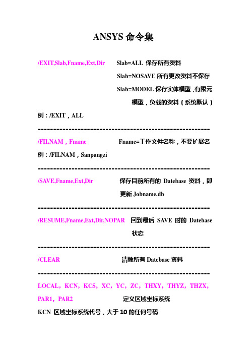
ANSYS命令集/EXIT,Slab,Fname,Ext,Dir Slab=ALL 保存所有资料Slab=NOSA VE所有更改资料不保存Slab=MODEL保存实体模型,有限元模型,负载的资料(系统默认)例:/EXIT,ALL-------------------------------------------------------- /FILNAM,Fname Fname=工作文件名称,不要扩展名例:/FILNAM,Sanpangzi--------------------------------------------------------/SA VE,Fname,Ext,Dir 保存目前所有的Datebase资料,即更新Jobname.db--------------------------------------------------------/RESUME,Fname,Ext,Dir,NOPAR 回到最后SA VE时的Datebase状态--------------------------------------------------------/CLEAR 清除所有Datebase资料-------------------------------------------------------- LOCAL,KCN,KCS,XC,YC,ZC,THXY,THYZ,THZX,PAR1,PAR2 定义区域坐标系统KCN 区域坐标系统代号,大于10的任何号码KCS=0,1,20=笛卡儿坐标1=圆柱坐标2=球面坐标XC,YC,ZC 该区域坐标原点与整体坐标原点的关系THXY,THYZ,THZX 该区域坐标与整体坐标XYZ轴的关系例:LOCAL,11,1,1,1,0-------------------------------------------------------- CSYS,0,1,2声明当前坐标系统例:CSYS,0-------------------------------------------------------- /UNITS,LABEL 声明系统分析时所用的单位LABEL=SI (米,千克,秒)LABEL=CGS (厘米,克,秒)LABEL=BFT (英尺)LABEL=BIN (英寸)例:LABEL,SI-------------------------------------------------------- /PREP7进入通用前处理器-------------------------------------------------------- N,NODE,X,Y,Z,THXY,THYZ,THZX 定义节点NODE 节点号码X,Y,Z 节点在当前坐标系中位置例:N,1,2,3,4-------------------------------------------------------- NDELE,NODE1,NODE2,NINC 删除已建立的节点NODE1,NODE2 删除从NODE1到NODE2的节点,如1到100 NINC 间隔号码,1为1到100全删,2为1,3,5 (99)例:NDELE,1,100,2--------------------------------------------------------NPLOT,KNUM 将节点显示在图形窗口中KNUM=0不显示节点号码KNUM=1显示节点号码--------------------------------------------------------NLIST,NODE1,NODE2,NINC将节点资料列在窗口中例:NLIST--------------------------------------------------------NGEN,ITIME,INC,NODE1,NODE2,NINC,DX,DY,DZ,SPACE 复制节点ITIME 复制次数,包括本身INC复制时节点号码增量NODE1,NODE2,NINC 要复制的节点DX,DY,DZ 复制出的节点的位置改变量例:NGEN,4,5,1,5,1,1,2,3 将节点1到5复制4次,每次复制X,Y,Z方向分别移动1,2,3单位长度-------------------------------------------------------- FILL,ITIME,INC,NODE1,NODE2,NINC,DX,DY,DZ,SPACE 填充节点(默认为均分填充)例:FILL,1,100 在节点1到100之间填充2,3 (99)-------------------------------------------------------- ET,ITYPE,Ename,KOPT1……KOPT6,INOPR 定义元素ITYPE 元素类型编号Ename 所使用元素名称KOPT1-KOPT6 元素特性编码例:ET,1,LINK1 第1类元素为LINK1单元-------------------------------------------------------- MP,Lab,MAT,C0,C1,C2,C3,C4 定义材料特性材料特性为固定值,其值为C0材料特性随温度变化,由C1-C4控制Lab 材料特性类别MAT 对应ET所定义的元素类型编号ITYPELab=EX,EY,EZ 杨氏系数Lab=DENS 密度Lab=PRXY,PRYZ,PRZX 泊松比Lab=GXY,GYZ,GZX 剪力模数例:MP,EX,1,207E9 第一类元素的杨氏系数为207E9-------------------------------------------------------- R,NSET,R1……R6 定义元素类型几何特性NSET 属性组别号码(系统默认值1)R1-R6 所定义元素类型几何特性值例:R,1,1E-4,2.09E-10 ,0.005-------------------------------------------------------- E,I,J,K,L,M,N,O,P定义元素连接方式I-P 定义元素节点顺序的号码例:E,1,2,5,7 四节点元素的节点顺序为1,2,5,7-------------------------------------------------------- EPLOT,KNUM 将元素显示在图形窗口中ENUM=0 不显示元素ENUM=1 显示元素-------------------------------------------------------- ELIST 将元素资料列在窗口中-------------------------------------------------------- EDELE,IEL1,IEL2,INC 删除已建立的元素IEL1,IEL2,INC 欲删除元素的范围例:EDELE,1,10,1-------------------------------------------------------- EGEN,ITIME,NINC,IEL1,IEL2,IEINC,MINC,IINC,RINC,CINC,DX,DY,DZ 复制元素ITIME 复制次数,包括本身NINC复制时节点号码增量IEL1,IEL2,IEINC 欲复制的元素范围DX,DY,DZ 复制出的元素的位置改变量例:EGEN,6,12,1,4,1 将元素1到4复制6次-------------------------------------------------------- /PNUM,Label,KEY 在图形中显示号码Label=NODE,ELEM,KP,LINE,AREA,VOLUKEY=0 不显示号码KEY=1 显示号码例:/PNUM,ELEM,1-------------------------------------------------------- /SOLU 进入解题处理器--------------------------------------------------------ANTYPE,Antype,Status 声明分析类型Antype=STATIC or 0 静态分析(系统默认)Antype=BUCKLE or 1 屈曲分析Antype=MODAL or 2 振动模态分析Antype=HARMIC or 3 调和外力动力系统分析Antype=TRANS or 4 瞬时动力系统分析例:ANTYPE,STATIC-------------------------------------------------------- F,NODE,Lab,V ALUE,V ALUE2,NEND,NINC定义节点上的集中力NODE 节点号码Lab 外力形式Lab=FX,FY,FZ,MX,MY,MZ 结构力学Lab=HEAT 热学的热流量Lab=AMP,CHRG 电学的电流,电荷Lab=FLUX 磁学的磁通量V ALUE 外力大小NODE,NEND,NINC 施力节点范围例:F,1,FY,,-200,5,1 =F,ALL,FY,-200 节点1-5 的Y方向定义集中力-200(注意FY,,表明V ALUE2默认)--------------------------------------------------------FDELE,NODE,Lab,NEND,NINC 删除节点集中力例:FDELE,1,FY,5,1 = FDELE,ALL--------------------------------------------------------D,NODE,Lab,V ALUE,V ALUE2,NEND,NINC,Lab2,Lab3,Lab4,Lab5,Lab6 定义节点自由度的限制NODE,NEND,NINC 选取自由度约束节点的范围Lab 相对元素每一个节点受自由度约束的形式结构力学Lab=UX,UY,UZ(直线位移)Lab=ROTX,ROTY,ROTZ(旋转位移)例:D,1,UX,,,5,1 节点1到5 X方向约束D,1,UX,,,5,1,UY 节点1到5 X Y方向约束D,1,ALL,,,5,1 节点1到5 全部自由度约束注意:使用命令前要先定义元素--------------------------------------------------------DDELE,NODE,Lab,NEND,NINC 取消节点自由度约束例:DDELE,ALL-------------------------------------------------------- DLIST,NODE1,NODE2,NINC 列出节点自由度约束--------------------------------------------------------DL,LINE,AREA,Lab,V ALUE1,V ALUE2定义线自由度限制LINE 线号AREA 线所属面积例:DL,8,3,ALL 定义面积3上面线8的约束注意:同时有DLLIST,DLDELE命令--------------------------------------------------------SFBEAM,ELEM,LKEY,Lab,V ALI,V ALJ,V AL2I,V AL2J,IOFFST,JOFFST定义分布力作用于梁元素的方式及大小ELEM 分布力所作用的元素编号LKEY 梁元素的4个面中分布力所在面号码Lab=PRES (表示分布压力)V ALI,V ALJ 在I,J点分布力的值例:SFBEAM,1,1,PRES,60,30 元素1上1号面作用分布力SFBEAM,1,1,PRES,-30,60--------------------------------------------------------SFE,ELEM,LKEY,Lab,KV AL,V AL1,V AL2,V AL3,V AL4定义分布力作用于元素上的方式及大小ELEM 分布力所作用的元素编号LKEY 分布力作用边,面的号码Lab=PRES (表示分布压力)V AL1-V AL4 分布力在元素边,面上节点的值例:SFE,4,2,PRES,,20,60元素4的第2边,面作用分布力--------------------------------------------------------SF,NLIST,Lab,V ALUE,V ALUE2 定义节点间分布力NLIST 分布力作用边或面上所有节点Lab=PRES例:SF,ALL,PRES,10注意:SFE适用于非均匀分布力,作用在元素的边或面上SF适用于均匀分布力,作用在节点之间-------------------------------------------------------- SFLIST,NODE,Lab 显示分布力-------------------------------------------------------- NSEL,Type,Item,COMP,VMIN,VMAX,VINC,KABS节点选择命令Type 选择方式Type=S 选择一组节点为ACTIVE点Type=R 在现有ACTIVE点中选出一部分作为ACTIVE点Type=A 在选择一部分节点,加入ACTIVE点中Type=U 在现有ACTIVE点中,排除某些节点Type=ALL 选择全部节点作为ACTIVE点Item =NODE 用节点号码选取┇Item =LOC 用节点坐标选取COMP=无┇COMP=X 以节点X坐标为准VMIN,VMAX,VINC 节点选取范围例:NSEL,S,NODE,,1,13,1选1-13中奇数点为ACTIVE点NSEL,A,NODE,,14,20,1 选14-20加入ACTIVE点--------------------------------------------------------OUTPR,Item,FREQ,Cname 分析结果是否显示于输出窗口Item=ALL 所有结果Item=NSOL 节点自由度结果FREQ 负载的次数FREQ=ALL 最后负载例:OUTPR,ALL,ALL注意:仅用于小程序--------------------------------------------------------SOLVE 开始解题--------------------------------------------------------/POST1 进入后处理器--------------------------------------------------------PLDISP,KUND 显示结构变形结构KUND=0 显示变形后结构形状KUND=1 显示变形前后结构形状KUND=0 显示变形前后结构形状,但仅显示外观--------------------------------------------------------PLESOL,Item,Comp显示元素的解答Item(何种解答)Comp(Item分量)S X,Y,Z,XY,YZ,ZX 应力S 1,2,3 主应力S EQV,INT 等效应力F X,Y,Z 结构力M X,Y,Z 结构力矩例:PLESOL,S,X,Y,Z--------------------------------------------------------PLNSOL,Item,Comp显示节点的解答Item(何种解答)Comp(Item分量)S X,Y,Z,XY,YZ,ZX 应力S 1,2,3 主应力S EQV,INT 等效应力F X,Y,Z 结构力M X,Y,Z 结构力矩U X,Y,Z,SUM 位移ROT X,Y,Z,SUM 旋转位移例:PLNSOL,S,Y PLNSOL,U,X--------------------------------------------------------PRESOL,Item,Comp 打印元素解答Item(何种解答)Comp(Item分量)S X,Y,Z,XY,YZ,ZX 应力F X,Y,Z 结构力M X,Y,Z 结构力矩例:PRESOL,S,X--------------------------------------------------------PRNSOL,Item,Comp 打印节点解答Item(何种解答)Comp(Item分量)U X,Y,Z 位移U X,Y,Z方向及总向量方向位移S COMP 应力S PRIN 主应立,等效应力例:PRNSOL,U PRNSOL,S注意:查看结果通常使用PLDISP,1 PLNSOL,U,Y……PRNSOL,S其中PLNSOL中Comp不能省略,PRNSOL中可以省略--------------------------------------------------------TYPE,Itype 声明建立元素时,元素形式号码(对应ET的Itype)例:ET,1,LINK1 ET,2,PLANE42TYPE,1建立LINK1元素TYPE,2建立PLANE42元素--------------------------------------------------------REAL,NSET 声明建立元素时,元素几何参数属性编号(对应R,NSET)--------------------------------------------------------MAT,MAT 声明建立元素时,元素材料特性属性编号(对应MP,MAT)--------------------------------------------------------LSWRITE,LSNUM 多重负载资料保存至文件Jobname.S0i 例:LSWRITE 自动编号,不用输入--------------------------------------------------------LSSOLVE,SLMIN,LSMX,LSINC读取所定义的多重负载并解答SLMIN,LSMX,LSINC 读取负载的范围例:LSSOLVE,1,4 获得1-4负载的解答--------------------------------------------------------DDELE,NODE,Lab,NEND,NINC删除定义的约束条件NODE,NEND,NINC 删除约束的节点范围Lab删除约束的节点方向例:DDELE,1,UY,5,2 删除1,3,5节点的Y向约束--------------------------------------------------------FDELE,NODE,Lab,NEND,NINC删除定义的集中力NODE,NEND,NINC 删除集中力的范围Lab删除外力的方向例:FDELE,1,FY,5,2 删除1,3,5节点的Y向集中力--------------------------------------------------------SFDELE,Nlist,Lab 将已定义的面载荷删除Nlist 面负载所含的节点(由NSEL选择,设Nlist=ALL)Lab=PRES (结构力学)--------------------------------------------------------SFEDELE,ELEM,LKEY,Lab 将负载从元素上删除ELEM 元素编号LKEY 负载作用边,面的号码Lab=PRES (结构力学)--------------------------------------------------------SET,Lstep,SBSTEP,FACT,KIMG,TIME,NGLE,NSET检查负载结果Lstep=负载编号例:SET,2 检查第二负载的结果PLDISP,1……注意:此命令要在/POST1中使用-------------------------------------------------------- FILE,Fname,Ext,Dir 读取分析后的结果文件例:FILE,TEST,RST--------------------------------------------------------ANTYPE,Antype,Status 声明分析类型例:ANTYPE=MODAL or 2 模态分析-------------------------------------------------------- MODOPT,Method,NMODE,FREQB,FREQE,PRMODE,NUMKEY 选择模态分析方法Method=REDUC 降阶法Method=SUBSP 次空间法NMODE 欲求模态个数(降阶法小于主自由度一半)FREQB,FREQE 欲探讨振动频率范围(默认全部)PRMODE 分析后,模态结果保存到结果文件的个数例:MODOPT,SUBSP,5-------------------------------------------------------- M,NODE,Lab1,NEND,NINC,Lab2。
- 1、下载文档前请自行甄别文档内容的完整性,平台不提供额外的编辑、内容补充、找答案等附加服务。
- 2、"仅部分预览"的文档,不可在线预览部分如存在完整性等问题,可反馈申请退款(可完整预览的文档不适用该条件!)。
- 3、如文档侵犯您的权益,请联系客服反馈,我们会尽快为您处理(人工客服工作时间:9:00-18:30)。
(and for g = 1 holomorphicity conditions at the cusps of Γ.) The space of modular forms is denoted by Mg k (Γ, ̺). In particular, we g g set Mk (Γ) := Mk (Γ, idΓ ). The normalized Eisenstein series Ek (τ ) (τ ∈ H1 ) are defined by Ek (τ ) = 1 − 2k Bk
(2.4)
This action is not effective, but Sp(2g, R)/{±Ig } acts effectively on Hg . An important subgroup of Sp(2g, R) is the Siegel modular group Γg := Sp(2g, Z) which acts properly discontinuously on Hg . For a function F on Hg , we introduce the weight-k slash operation by (F |k γ ) (Ω) := det(C Ω + D )−k F (γ · Ω) , where k ∈ Z and γ is as in (2.4). Definition 2.1. Let Γ be a finite index subgroup of Γg (g ∈ N) and let ̺ : Γ → C× := C {0} be a character. A holomorphic function F : Hg → C is called a modular form of weight k (k ∈ Z) with character ̺ if F satisfies (F |k γ ) (Ω) = ̺(γ )F (Ω), (∀γ ∈ Γ) , (2.6) (2.5)
This is a survey of somewhat mysterious connections found recently between K 3 surfaces and the Igusa cusp form of weight ten χ10 . Gritsenko and Nikulin [GN1] following the method of Borcherds [Bor1] proved a remarkable infinite product formula of χ10 . The exponents of the factors appearing in their infinite product coincide with the coefficients in the expansion of the elliptic genus of K3 surfaces. The aim of this survey is to try to look at this coincidence more carefully. Borcherds-type infinite products appear naturally in some sort of modular integrals associated with one-loop calculations of string theory as pointed out by Harvey and Moore [HM]. They used the method developed by Dixon, Kaplunovsky and Louis (DKL) [DKL]. In sect.6, I present a similar calculation [Kaw1] for the case of our present interest. The approach taken is again that of DKL, which may now fairly be said to be standard, but I will be more careful about the so-called “degenerate orbits” explaining the relevance of the Kronecker limit formulas. The Igusa cusp form χ10 [Igu] made its appearance in the past in the two-loop calculations of critical bosonic string theory [Two]. Thus one is naturally led to the expectation that K3 surfaces might be related to bosonic string. In fact, Vafa and Witten [VW] pointed out the connection between K3 surfaces and bosonic string in the context of G¨ ottsche’s formula [Goe]. They gave a physical derivation of the orbifold version [HH] of G¨ ottsche’s formula. This method of Vafa and Witten has recently been extended by Dijkgraaf et al. [DMVV] for the computation of the generating function of the orbifold elliptic genera of symmetric products of K3 surfaces. In sect.7, I give some interesting interpretation of their result
K3 Surfaces, Igusa Cusp Form and String Theory
Toshiya Kawai
arXiv:hep-th/9710016v7 23 Dec 1997
Abstract It has recently become apparent that the elliptic genera of K3 surfaces (and their symmetric products) are intimately related to the Igusa cusp form of weight ten. In this contribution, I survey this connection with an emphasis on string theoretic viewpoints. 1. Introduction
2
T. Kawai
taking the relation between χ10 and the two-loop vacuum amplitude of bosonic string seriously. The two subjects treated in sect.6 and sect.7 are not logically connected and it is desirable to gain a conceptual as well as rigorous understanding of why they exhibit a parallelism. However, there have been interesting proposal and argument regarding this in conjunction to string duality [DVV][DMVV]. We also note that in addition to the works mentioned, the Igusa cusp forms have been used in other aspects of string theory [MS] [Kaw2] [CCL]. Sects.2–5 are devoted to preliminary materials. In sect.2, we review the definitions of Siegel modular forms and Jacobi forms. In sect.3, we summarize the fundamental properties of elliptic genera. In sect.4, we investigate in detail the elliptic genus of K3 surfaces. In sect.5 we review the infinite product formula of Borcherds, Gritsenko and Nikulin. Finally, in sect.8, we point out what remains to be clarified. Notation. R: the set of real numbers. C: the set of complex numbers. Z: the set of integers. N: the set of positive integers. N0 : the set of non-negative integers. M(n, R): the set of n × n real matrices. M(n, C): the set of n × n complex matrices. M(n, Z): the set of n × n integer matrices. In : the n × n √identity matrix. e[x]: exp(2π −1x). 2. Siegel modular forms and Jacobi forms First I recall some fundamental materials from the theory of Siegel modular forms [Fre] and that of Jacobi forms [EZ]. The Siegel upper space of genus g ∈ N is defined by Hg := {Ω ∈ M(g, C) | Ω = t Ω, The symplectic group Sp(2g, R) := {γ ∈ M(2g, R) | t γJγ = J }, J= 0 Ig −Ig 0 , (2.2) Im(Ω) > 0} . (2.1)