在ISE下分析和约束时序
ise设计分析

AES电路设计与分析本次的目的在于熟悉ISE中对静态时序的分析,以及如何对设计进行检错以及修改优化。
本次所要进行优化分析的代码是关于AES密码,本次使用的分析软件为ISE9.1.本次所要实现在过程如下:1.建一个关于AES的工程,输入AES代码后使用ISE9.1进行综合。
2.进行管脚约束。
3.进行面积约束。
4.分析综合报告,对静态时序进行分析。
5.根据综合报告观察时钟是否能够满足要求。
6.如果不满足要求不断的进行修改,直到能满足时序要求为止。
7.最后进行一定的优化。
分析方法与步骤如下:1.打开ISE9.1新建一个工程,并添加源代码,本次使用的设计参数为xc4vfx140-11ff1517。
选择user constraints-assign package pins进行管脚约束。
进入xilinx pace界面以后选择package view,将管脚拉到package view 窗口中的空格子中,注意时钟必须放在正确的位置上,可以选择view-toolbars-legend在出现的窗口中有对各种类型的格子的说明。
设置完管脚后点击保存。
关闭窗口。
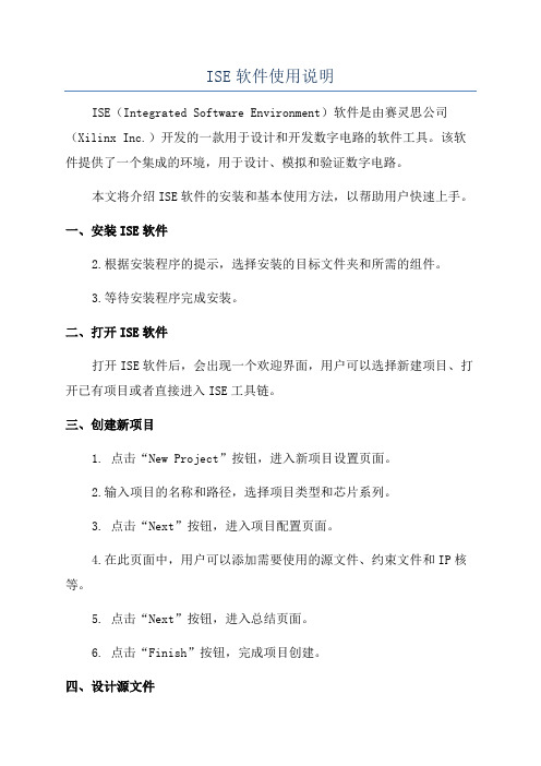
2.首先进行synthesize-XST分析,而在此分析中也可以对优化目标进行一些设置,选中synthesize-XST选项,右击选择属性(properties),得到的窗口如图1所示,其中的Global Optimization Goal选项指的是优化的目标,可以在此进行一定的设置,如图所示所有的时钟线,优化逻辑最大延迟,建立时间,保持时间等;图1双击synthesize-XST下的View synthesis Report,以下是其部分报告及分析:Timing Summary:---------------Speed Grade: -11Minimum period: 1.901ns (Maximum Frequency: 525.984MHz)Minimum input arrival time before clock: 3.180nsMaximum output required time after clock: 4.221nsMaximum combinational path delay: No path found分析:这里的第一项Minimum period指的是最小的逻辑延迟第二项Minimum input arrival time before clock指的是数据必须在时钟上升延到来之前的3.180ns把数据准备好,相当于建立时间。
ISE软件使用说明(两篇)

引言:概述:ISE软件是由Xilinx公司开发的一款集成电路设计工具,使用该软件可以进行数字电路设计、仿真、验证以及实现等多个阶段的工作。
在设计阶段,ISE软件提供了丰富的组件库和设计工具,方便用户进行电路原理图的绘制和逻辑设计。
在验证阶段,ISE软件可以进行功能仿真和时序仿真,以确保设计的正确性和稳定性。
在实现阶段,ISE软件提供了先进的布局与布线工具,能够将设计转化为实际的电路板。
正文内容:1.安装与启动1.1ISE软件安装包1.2安装ISE软件1.3启动ISE软件2.项目管理2.1创建新项目2.2导入已有项目2.3添加设计文件2.4设定项目属性2.5保存和备份项目3.设计流程3.1电路原理图设计3.1.1组件选择3.1.2连接元件3.1.3设置元件属性3.2逻辑设计3.2.1设计约束3.2.2逻辑优化3.2.3时序约束3.3约束文件编辑3.3.1约束规则3.3.2约束语法3.3.3约束检查3.4时序仿真3.4.1创建仿真波形3.4.2设定初始状态3.4.3运行仿真3.5功能仿真3.5.1设置输入信号3.5.2运行仿真3.5.3分析仿真结果4.仿真与验证4.1时序分析4.1.1设定时钟4.1.2时序路径分析4.1.3时序优化4.2时序约束验证4.2.1满足约束4.2.2修复时序错误4.3灵敏度分析4.3.1设定输入敏感性4.3.2分析敏感性4.4逻辑分析4.4.1切换敏感性4.4.2分析逻辑状态5.布局与布线5.1物理约束5.1.1面积约束5.1.2信号完整性约束5.1.3电源与接地约束5.2布局5.2.1网表导入5.2.2管理物理资源5.2.3进行布局布线5.3时序优化5.3.1满足时序约束5.3.2缩短信号传输路径5.3.3优化时钟分配5.4布线5.4.1管理布线资源5.4.2进行布线5.4.3路由与优化5.5设计规约检查5.5.1检查布局布线规约5.5.2修复设计规约错误总结:引言概述:ISE软件是一款功能强大的集成开发环境工具,广泛应用于数字电路设计和实现。
第六章-约束设计与时序分析

第六章 约束设计与时序分析§6.1 概述对于一些普通的、低速的逻辑设计来说,在经过了ISE 6设计工具的综合、优化处理之后,不用再进行时序方面的任何分析和处理基本上就可达到和满足设计要求。
然而对于高速、高性能、高密度以及多时钟信号控制的逻辑设计,仅靠ISE 6的优化处理是远远不够的,而需要对设计进行时序方面的控制和处理并进行严格的时序分析,以判定所完成的设计是否达到我们的设计要求。
通常,在进行这些设计时,对时序问题作出判断和处理的越早越好。
Xilinx针对这些高端的逻辑设计,在ISE6设计工具提供了功能完善和强大的时序分析器(Timing Analyzer),其详细的时序报告功能方便确定高速信号的路径。
通过该工具,设计者可对设计中的时序冲突以及时序约束等进行细致的检查,找到设计中的时序瓶颈,然后通过一些特定的处理方法对时序进行调整。
这些设计和分析方式我们称为时序收敛(迭代)。
ISE6设计工具所提供的主动时序收敛(ProActive Timing Closure)技术,保证了FPGA器件的高速设计能力,从而降低总体设计成本以及整个设计流程所花费的时间。
作为构成时序收敛技术的一部分,ISE 6工具中新的时序约束(Timing Constraints)提供了可编程逻辑设计中最全面的时序约束语言。
这些都进一步简化了高速设计和分析。
通常,对于复杂的设计,需要进行反复的时序分析和约束设计,即多次迭代,以满足设计的要求。
Xilinx推荐的设计流程如图6-1所示。
图6-1 完整的Xilinx 逻辑设计和时序收敛流程约束设计条件可以在设计文件中直接设置,也可以通过用户约束文件UCF (User Constraint File)、网表约束文件NCF (Netlist Constraint File)、物理约束文件PCF(Physical Constraints File)等形式进行设置。
在Xilinx的CPLD/FPGA设计中,约束条件主要包括:⑴ CPLD约束(CPLD Fitter)--CPLD约束用于指定CPLD设计中的各类约束参数。
XilinxISE下的静态时序分析与时序优化

XilinxISE下的静态时序分析与时序优化单击Design Summary中的Static Timing就可以启动时序分析器(Timing Analyzer)。
在综合、布局布线阶段ISE就会估算时延,给出⼤概的时延和所能达到的最⼤时钟频率,经过PAR后,在Static Timing中给出的是准确的时延,给出的时序报告可以帮助我们找到关键路径,然后针对其进⾏优化,提⾼系统的时钟频率。
这⾥的Minimum period指的是最⼩的逻辑延迟;造成时序性能差的原因很多,主要缘由以下⼏种:1. 布局太差⼀般和代码本⾝没有关系。
解决⽅案:只能从软件⾃⾝的布局算法考虑(调整布局的努⼒程度)或者使⽤⾼端芯⽚2. 逻辑级数太多逻辑级数越多,资源的利⽤率越⾼,但是对⼯作频率的影响也越⼤。
解决⽅案:1.使⽤流⽔线技术;2.如果是多周期路径,添加多周期约束;3.良好的编码习惯,不要过多嵌套if-else,尽量使⽤case代替if语句。
3. 信号扇出过⾼⾼扇出会造成信号传输路径过长,从⽽降低时序性能。
解决⽅案:1.逻辑复制;2.区域约束,想过逻辑放置在⼀起。
4. 不要同时使⽤双边沿触发FPGA的底层⼯艺都是单向的同步电路,所以本⾝不⽀持统⼀信号的双边沿触发,ISE在实际处理的时候,会⾃动将该信号2倍频,然后利⽤第⼀个沿处理上升沿,第⼆个沿处理下降沿。
这样在分析时序时,⾃动把约束升级为ucf⽂件中的两倍。
5. Xilinx最优时序解决⽅案1.I/O约束 根据Xilinx器件的特点,控制信号置于器件的顶部或底部,且垂直布置;数据总线的I/O置于器件的左右两侧,且⽔平布置,这样可以最⼤程度的利⽤芯⽚底层结构。
2.ISE实现⼯具 ISE中的⼯具具备不同的努⼒程度,直接使⽤最⾼级别的可以提⾼时序性能,但是会耗费很多时间,所以应该逐步调整努⼒程度。
第⼀遍使⽤默认的参数选项,如果不满⾜再调整综合、映射、布局布线的参数。
时序优化的若⼲策略优化⽅向⼀:合理使⽤Blcok RAM和Distributed RAM1. 均衡Block RAM和Distributed RAM的使⽤。
ISE软件使用说明
ISE软件使用说明ISE(Integrated Software Environment)软件是由赛灵思公司(Xilinx Inc.)开发的一款用于设计和开发数字电路的软件工具。
该软件提供了一个集成的环境,用于设计、模拟和验证数字电路。
本文将介绍ISE软件的安装和基本使用方法,以帮助用户快速上手。
一、安装ISE软件2.根据安装程序的提示,选择安装的目标文件夹和所需的组件。
3.等待安装程序完成安装。
二、打开ISE软件打开ISE软件后,会出现一个欢迎界面,用户可以选择新建项目、打开已有项目或者直接进入ISE工具链。
三、创建新项目1. 点击“New Project”按钮,进入新项目设置页面。
2.输入项目的名称和路径,选择项目类型和芯片系列。
3. 点击“Next”按钮,进入项目配置页面。
4.在此页面中,用户可以添加需要使用的源文件、约束文件和IP核等。
5. 点击“Next”按钮,进入总结页面。
6. 点击“Finish”按钮,完成项目创建。
四、设计源文件在ISE软件中,用户可以使用HDL(硬件描述语言)进行设计源文件的编写。
ISE软件支持的HDL语言有VHDL和Verilog。
1. 在项目视图中,右键点击“Source”文件夹,选择“New Source”。
2.在弹出的对话框中,选择源文件类型和语言。
3. 输入文件的名称和路径,点击“Finish”按钮。
五、添加约束文件约束文件用于定义电路的时序、引脚映射等信息,以确保电路的正常工作。
1. 在项目视图中,右键点击“Constraints”文件夹,选择“New Source”。
2.在弹出的对话框中,选择约束文件类型。
3. 输入文件的名称和路径,点击“Finish”按钮。
六、综合与实现在进行综合和实现之前,需要根据设计需求进行一些设置和配置。
1. 在项目视图中,右键点击项目名称,选择“Properties”。
2.在弹出的对话框中,选择“SYNTHESIS”或“IMPLEMENTATION”选项卡。
ISE的使用说明

ISE的使用说明ISE(Integrated Software Environment)是一种集成软件环境,用于设计和验证硬件开发项目。
它由Xilinx公司开发,旨在为FPGA(Field-Programmable Gate Array)和SoC(System-on-a-Chip)设计提供完整的解决方案。
ISE具有多种功能和工具,可以帮助工程师在整个开发过程中完成各种任务。
ISE的安装:ISE的主要功能:ISE为硬件设计和验证提供了全面的解决方案。
以下是ISE的主要功能:2.综合和优化:ISE包含了综合和优化工具,将HDL代码转换为布尔函数表示。
综合工具会分析代码并生成等效的硬件电路电路。
优化工具会尝试将电路改进为更有效的形式,以提高性能和减少资源消耗。
3.约束和分析:在设计过程中,您通常需要对硬件进行约束,以满足特定的要求。
ISE提供了工具来定义时序约束、电气约束和物理约束,并分析设计是否满足这些约束。
4.实现和布局:一旦设计和优化完成,ISE将使用实现和布局工具将电路映射到目标FPGA或SoC中。
这些工具将选择适当的逻辑资源,并将其布局在特定的芯片区域,以最大程度地提高性能和效率。
5.仿真和调试:在设计过程中,您需要对硬件进行仿真和调试,以验证其正确性和性能。
ISE提供了仿真工具,可以对设计进行功能仿真、时序仿真和混合信号仿真。
它还提供了调试功能,可帮助您定位和解决问题。
以下是使用ISE的一般步骤:1.创建新工程:在ISE中,您需要先创建一个新的工程,用于存储和组织设计文件。
可以在ISE中创建一个新的工程,并选择适当的目标设备。
2. 添加设计文件:一旦工程创建完成,您可以添加设计文件到工程中。
通过右键单击工程文件夹,并选择“Add Source”来添加设计文件。
选择适当的文件类型,并在文件对话框中选择要添加的文件。
3. 设置约束:在设计过程中,您需要为硬件设计设置约束,以满足特定的要求。
通过右键单击工程文件夹,并选择“Add Constraints”来添加约束文件。
ISE时序约束总结2

Timing Groups and OFFSET ConstraintsObjectivesAfter completing this module, you will be able to:•Use the Constraints Editor to create groups of path endpoints •Use the Constraints Editor to create path-specific OFFSET constraintsOutline•Introduction •Creating Groups •OFFSET Constraints •SummaryPath-Specific TimingConstraints•Using global timing constraints (PERIOD, OFFSET, and PAD-TO-PAD) will constrain your entire design•Using only global constraints often leads to over-constrained designs –Constraints are too tight–Increases compile time and can prevent timing objectives from being met–Review performance estimates provided by your synthesis tool or the Post-Map Static Timing Report•Path-specific constraints override the global constraints on specified paths –This allows you to loosen the timing requirements on specific pathsMore About Path-Specific Timing Constraints•Areas of your design that may benefit from path-specific constraints –Multi-cycle paths–Paths that cross between clock domains–Bidirectional buses–I/O timing•Path-specific timing constraints should be used to define your performance objectives and should not be indiscriminately placedGlobal Constraint Review•Using the global PERIOD, OFFSET IN, and OFFSET OUT constraints will constrain all of these paths•This makes it easy to control the overall performance of your designCDATAPath-Specific Constraint Example• A path-specific constraint can optimize as little as one path•This gives you greater control over your design’s performance and gives the implementation tools the greatest flexibility in meeting your performanceand utilization needsCDATAThe Advanced Tab of the Constraints Editor•Creating path-specificconstraints requires two steps–Step 1:Create groups of pathend points–Step 2:Communicate thetiming objective between thegroups•The constraints we discuss inConstraints EditorOutline •Introduction•Creating Groups •OFFSET Constraints •SummaryCreating Groups of Endpoints•Path-specific timing constraints will only be effective if path end points can be easily grouped together–Otherwise, constraining a large design would be time consuming and painstaking•The Constraints Editor makes this easy by allowing you to define groups of path end points (pads, flip-flops, latches, and RAMs)•Specific delay paths can then be constrained with advanced timing constraintsCreating Groups of Endpoints•With the Constraints Editor,grouping path end points ismade easy with the followingoptions:–Group by nets–Group by instance name–Group by hierarchy–Group by output net name–Timing THRU Points option–Group by clock edgeGrouping by Nets orOutput Net Name •Step 1: Enter a group name•search for–Optional filter string•Available list•Step 3: Select nets and click Add–Nets appear in the Time NameTargets listGrouping by Nets versusOutput Net Name•Grouping by net “NET_A”will create a group containing FLOP2 only –Group contains flip-flops that are driven by the selected net •Grouping by output new “NET_A”will create a group containing FLOP1only–Group contains the flip-flop that sources the selected net•Steps are the same•Design Element Types are different–Instance Name: FFs, pads, latches, RAMs–Hierarchy: User levels, Xilinx-created levelsGrouping by Instance Nameor Hierarchy••defined group–the group•Step 3: Select clock edgeGrouping by Clock EdgeTiming THRU Points•Allows you to optimize paths through specific nets and 3-state buffers•In this example, a group of nets was named TEOUTS. A constraint can now be referenced such that only the delay paths through the TEOUTS nets will be optimizedTiming THRU Points•Group nets or 3-state buffers •Use these groups to identifyspecific paths to be constrainedManaging Groups•Groups that you have defined are written into the UCF file–INST <element_name> TNM = <group_name>; OR–NET <net_name> TNM_NET = <group_name>; OR–TIMEGRP <group_name> = <elements>;•To add items to an existing group, click one of the grouping buttons and use the same Time Name–Not allowed when grouping by output net name•To delete a group, right-click on the line in the Constraints window and select Delete Constraint–Or delete the line with a text editor•You cannot remove items from a group with the Constraints Editor –Edit the UCF file with a text editorOutline•Introduction •Creating Groups•OFFSET constraints •SummaryReview of Global OFFSETConstraints•Use the Pad-to-Setup and Clock-to-Pad columns to specify OFFSETs for all I/O paths on each clock domain•Easiest way to constrain most I/O paths–However, this may lead to an over-constrained designPin-Specific OFFSETConstraints•Use the Pad-to-Setup and Clock-to-Pad columns to specify OFFSETs for each I/O pin•Use this type of constraint when only a few I/O pins need different timingCreating Groups of Pads •Groups of I/O pads can be made in the Ports tab–Use Shift-click or CTRL-click to select multiple pads–Enter a group name and click the Create Group button•Click the Pad to Setup or Clock to Pad button to define group OFFSETs –Or use the Advanced tabCreating Group OFFSETConstraints•OFFSET IN/OUTconstraints can also beentered in theAdvanced tab•The Pad-to-Setup andClock-to-Pad optionsallow you to enterOFFSET IN/OUTconstraints on specificgroups of padsGroup OFFSET Constraints•••Select a clock domain•Source SynchronousOFFSET Constraints•For source synchronous inputs, youcan specify the width of the validdata windowOFFSET Constraints withTwo-Phase Clocks•OFFSET constraints define the relationship between the data and the initial clock edge at the pins of the FPGA•Initial clock edge is defined in the global PERIOD constraint using the HIGH or LOW keyword–HIGH: Initial edge rising (default)–LOW: Initial edge falling•If all I/O are clocked on a single edge, use the HIGH/LOW keywords in the PERIOD constraint to define which edge is used•If both clock edges are used, create two OFFSET constraints –One for each clock edge–This includes cases where DDR flip-flops are usedOFFSET IN Using Both Clock Edges •Input data is valid 3 ns before rising and falling edge –PERIOD constraint is 10 ns, initial edge rising, 50-percent duty cycle •Create groups of flip-flops for each clock edge •For inputs clocked on a rising edge, OFFSET = IN 3 ns BEFORE clk;•For inputs clocked on a falling edge, OFFSET = IN –2 ns BEFORE clk;– 2 ns after initial (rising) edge = 3 ns before falling edgeclkOFFSET OUT Using Both Clock Edges•Output data must be valid 3 ns after rising and falling edge –PERIOD constraint is 10 ns, initial edge rising, 50-percent duty cycle •Create groups of flip-flops for each clock edge •For outputs clocked on a rising edge, OFFSET = OUT 3 ns AFTER clk;•For outputs clocked on a falling edge, OFFSET = OUT 8 ns AFTER clk;–8 ns after initial (rising) edge = 3 ns after falling edgeclkOutline•Introduction •Creating Groups •OFFSET Constraints•SummaryReview Questions•How do path-specific timing constraints improve your design’s performance?•How would you constrain this design to get an internal clock frequency of 100 MHz?•The input will be valid at least 3 ns before the rising edge of CLK. The output must be valid 4 ns after the falling edge of CLK. Write the appropriateOFFSET constraintsINCLKRESET_ARESET_BAnswers•How do path-specific timing constraints improve your design’s performance?–They give the implementation tools more flexibility to meet all of your timing objectives•How would you constrain this design to get a maximum internal clock frequency of 100 MHz?–Enter a global PERIOD constraint of 10 ns on the CLK signal•Write the appropriate OFFSET constraints.–Assuming that the PERIOD constraint uses the HIGH keyword and 50-percent duty cycle:•OFFSET = IN 3 ns BEFORE CLK;•OFFSET = OUT 9 ns AFTER CLK;Summary•Path-specific constraints are used to override global constraints –Keeps your design from becoming over-constrained–Allows the software to make intelligent trade-offs to meet all of your performance goals•Creating path-specific constraints is a two-step process–Create groups of path endpoints–Communicate the timing objective between the groups•Path-specific OFFSET constraints can be entered on either the Ports tab or the Advanced tab•When using both clock edges for I/O, write separate OFFSET constraints for each clock edgeWhere Can I Learn More?•Timing Presentation on the Web: →Tech Tips →Timing & Constraints•Constraints Guide: →Software Documentation –Documentation may also be installed on your local machine。
ise时钟约束写法
ise时钟约束写法
ISE (Integrated Software Environment) 是Xilinx公司的一款集成开发环境软件,用于FPGA设计。
在ISE中,时钟约束是指对时钟信号进行约束,以确保设计在时序上能够正确工作。
时钟约束的写法包括以下几个方面:
1. 周期约束,时钟的周期约束是指规定时钟信号的周期,以确保设计能够在指定的时钟周期内完成操作。
在ISE中,可以使用语法类似于“create_clock -period 10 [get_ports clk]”来指定时钟信号的周期为10个时钟周期。
2. 约束时钟延迟,除了周期约束外,还可以对时钟信号的延迟进行约束。
这可以通过语法类似于“set_clock_latency -max 2 [get_clocks clk]”来实现,其中“-max 2”表示最大延迟为2个时钟周期。
3. 时钟分配约束,在设计中可能存在多个时钟域,需要对时钟进行分配约束,以确保时序正确。
可以使用语法类似于
“create_clock -period 10 -name clk [get_ports clk]”来为特定时钟信号分配时钟域。
4. 时钟域约束,除了时钟分配约束外,还可以对时钟域进行约束,以确保时序正确。
可以使用语法类似于“derive_clocks -period 10 [get_pins {/clk}]”来为时钟域添加约束。
总之,在ISE中,时钟约束的写法需要遵循特定的语法规则,并且需要根据设计的实际情况进行合理的约束设置,以确保设计在时序上能够正确工作。
希望以上信息能够帮助你更好地理解时钟约束的写法。
- 1、下载文档前请自行甄别文档内容的完整性,平台不提供额外的编辑、内容补充、找答案等附加服务。
- 2、"仅部分预览"的文档,不可在线预览部分如存在完整性等问题,可反馈申请退款(可完整预览的文档不适用该条件!)。
- 3、如文档侵犯您的权益,请联系客服反馈,我们会尽快为您处理(人工客服工作时间:9:00-18:30)。
1. 在ISE下分析和约束时序3.1 ISE的时序约束工具入门像TimeQuest一样,ISE软件工具也有自己的时序约束及分析工具。
ISE界面的processes当中,有一个user constraints列表,其中的Creat Timing Constrain可以提供用户添加指定的时序约束。
ISE使用的时序约束信息跟其他的物理约束,电气约束等信息全部都放置在后缀名为ucf(user constrain file)的文件中,在使用图形化界面编辑约束后,用户还可以直接编辑UCF文件对时序等要求进行修改。
此外,PlanAhead Post synthesis工具在提供管脚,区域约束等功能之外,也提供了时序约束及分析的功能。
所以设计者在约束设计时序时可以有多种方法。
使用Creat Timing Constrain时界面的约束类型部分如下图所示:图 ISE时序约束类型从图中我们看到,这个工具对于时序约束的理解与altera的一致,需要约束时钟,输入输出信号,以及指定一些时序例外,也有将约束组成Group的功能。
Xilinx公司对于其FPGA约束的名称与altera略有不同,但含义一样。
分别是Period constrain(时钟周期约束),OFFSET constrain(输入输出偏移约束),以及FROM TO constrain,当然也有multi-cycle constrain等。
双击unconstrained clks窗口的clk项,出现的以下对话框可以对设计的时钟信息进行指定。
图ISE下约束时钟界面这个界面可以设置时钟的周期,占空比,以及初始边沿是上升沿还是下降沿。
或者如果这个时钟是从其他指定的时钟生成的,也可以指定生成的关系从而软件自己计算生成时钟的信息。
unconstrained clks窗口将设计中没有约束的时钟列出来,在对每个时钟一一指定之后,窗口内容逐一消失。
而其上方另一个窗口将显示约束的具体信息,并且也可从中选择一条约束进行逐一修改。
约束类型菜单下的Inputs 选中双击后,会出现如下图所示的对话框,指定了输入偏移约束的类型之后,选择next。
这里的OFFSET IN 的类型包括,输入信号是源同步还是系统同步(时钟的来源不同),是单边沿触发还是双边沿触发的信号,以及有效边沿类型。
通常在设计中,若非特殊的DDR数据,或者使用了外部随路时钟,就选择SDR以及系统同步即可。
图指定输入偏移约束的类型指定了偏移约束类型后选择next会出现下图所示页面,在这个页面中可以约束输入信号的时序。
图 OFFSET IN 约束设置页面在这个页面中,左上角表明了系统中使用的时钟的信息。
若有多个时钟,则可以选择输入信号建立相关的时钟。
在Input pad timegroup/net中,可以选择要指定约束的目标端口。
若没有对信号合并分组,就选择input pad net,然后选择需要约束的输入管脚即可。
画红色*号的必须指定的地方,会有External setup time,此即为需要设置的offset in 约束。
通过计算外部器件输出时序以及电路板上延时之后,设计者可以在此指定一个值,表示的是输入端口信号建立时间与时钟信号有效边沿的延时。
仿照上面OFFSET IN的设置,读者可以设置OFFSET OUT的约束。
它约束的是输出端口信号与参考时钟有效边沿之间的延时关系。
其数值需要查阅下一级芯片输入数据时钟的建立关系及电路板上时钟,信号线延时关系计算获得。
约束了设计中使用的时钟,同时约束了输入输出端口的时序之后,整个设计的约束就是完整的。
但完整的约束不一定是正确的,过于严格的约束会挤占布局布线的资源从而造成无法进行最优布线。
所以还需要对一些不必要的,过于严格的约束进行时序例外的声明。
这些读者可以通过尝试软件工具及阅读软件用户手册来学习。
保存了设置的时序后,在工程目录下的Ucf文件将进行更新,最新设置的时序结果将以文本形式体现在ucf文件中,例如以下字段:#Created by Constraints Editor (xc5vsx50t-ff1136-3) - 2011/09/04NET "clk" TNM_NET = clk;TIMESPEC TS_clk = PERIOD "clk" 20 ns HIGH 50%;NET "bu" OFFSET = IN 2 ns VALID 20 ns BEFORE "clk" RISING;这些不仅包括了时序约束,还以注释的形式将约束生成的日期以及针对的器件型号列出了。
设计者甚至可以通过编辑修改这里的文本来快速修改时序约束。
生成的ucf已经是在工程下了。
添加了约束后XST工具不需要重新运行,但是Implement Design下每一步都需要重新执行。
重新执行时,便是在我们设置的约束下进行映射及布局布线了。
下面是PlanAhead Post synthesis工具启动后设置时序约束的页面。
图PlanAhead Post synthesis工具下的时序约束界面从上图可以看出这里的时序约束包括了Clk period,Pad-clk offset,path delay,Time group,False path以及off chip delay等项。
双击其中的任何一项可以出现下图所示的对话框:图设置新的时序约束对话框这个对话框列出了所有能够设置的时序约束,这里的约束设置比Creat Timing Constrain工具更加简洁,如图中所示,在选择了Input pad to clk offset 之后,右边出来的界面中,选择data arrival为Before clock,时钟选择的clk为系统时钟,有效边沿选择上升沿,勾选Delay value,设置为2ns。
Pad net勾选后可以选择需要设置的端口名称。
这样的设置与前文所述的Creat Timing Constrain工具约束输入端口时序是一致的。
可见这个工具会更加简洁。
3.2 ISE下查看时序结果查看时序报告时,在ISE工具下也有多种方式。
比如,在ISE工具下可以选择Timing,然后在出现的对话框选择run analysis。
会出现下图所示界面。
在这个界面中可以选择需要分析的pad, net或者是寄存器(Flip-Flop)。
这样工具会给出你选择的路径的时序分析报告。
图 Run Timing Analysis对话框或者不选择分析的具体内容,而是直接在tools下选择Timing Analyzer,或者是在Place&Route下选择Generate post-Place&Route Static Timing下面的Analyze post-Place&Route Static Timing,都会出现一个以工程头文件命名的后缀为twx的一个报告框,这里面将包含设计的时序信息。
其中Timing summary下会有诸如以下的英文:Timing summary:---------------Timing errors: 0 Score: 0 (Setup/Max: 0, Hold: 0)Constraints cover xxx paths, xx nets, and xx connectionsDesign statistics:Minimum period: xxx ns{1} (Maximum frequency: xxx MHz)从这个报告一眼可以看出是否会存在时序错误,以及错误路径数量。
还包括时序约束信息覆盖的路径,网络以及连接关系,最后是最小周期,同时计算出该设计最高能够正确运行的频率。
在Timing constraints下,能够看到设计的一些时序约束信息,并且给每一条约束进行对应的分析,给出报告看是否能够满足约束。
典型摘录下来的一段如下:Paths for end point cnt_21 (SLICE_X24Y43.CIN), 20 paths--------------------------------------------------------------------------------Slack (setup path): 18.421 ns (requirement - (data path - clock path skew + uncertainty)) Source: cnt_0 (FF)Destination: cnt_21 (FF)Requirement: 20.000nsData Path Delay: 1.404ns (Levels of Logic = 6)Clock Path Skew: -0.140ns (1.095 - 1.235)Source Clock: clk_BUFGP rising at 0.000nsDestination Clock: clk_BUFGP rising at 20.000nsClock Uncertainty: 0.035nsClock Uncertainty: 0.035ns ((TSJ^2 + TIJ^2)^1/2 + DJ) / 2 + PETotal System Jitter (TSJ): 0.070nsTotal Input Jitter (TIJ): 0.000nsDiscrete Jitter (DJ): 0.000nsPhase Error (PE): 0.000nsMaximum Data Path: cnt_0 to cnt_21Location Delay type Delay(ns) Physical ResourceLogical Resource(s)------------------------------------------------- -------------------SLICE_X24Y38.AQ Tcko 0.346 cnt<3>cnt_0SLICE_X24Y38.A4 net (fanout=1) 0.278 cnt<0> SLICE_X24Y38.COUT Topcya 0.384 cnt<3>Mcount_cnt_lut<0>_INV_0Mcount_cnt_cy<3>SLICE_X24Y39.CIN net (fanout=1) 0.000 Mcount_cnt_cy<3> SLICE_X24Y39.COUT Tbyp 0.082 cnt<7>Mcount_cnt_cy<7>SLICE_X24Y40.CIN net (fanout=1) 0.000 Mcount_cnt_cy<7> SLICE_X24Y40.COUT Tbyp 0.082 cnt<11>Mcount_cnt_cy<11>SLICE_X24Y41.CIN net (fanout=1) 0.000 Mcount_cnt_cy<11> SLICE_X24Y41.COUT Tbyp 0.082 cnt<15>Mcount_cnt_cy<15>SLICE_X24Y42.CIN net (fanout=1) 0.000 Mcount_cnt_cy<15> SLICE_X24Y42.COUT Tbyp 0.082 cnt<19>Mcount_cnt_cy<19>SLICE_X24Y43.CIN net (fanout=1) 0.000 Mcount_cnt_cy<19> SLICE_X24Y43.CLK Tcinck 0.068 cnt<22>Mcount_cnt_xor<22>cnt_21------------------------------------------------- ---------------------------Total 1.404ns (1.126ns logic, 0.278ns route)(80.2% logic, 19.8% route)该报告分析了从cnt_0到 cnt_21的路径中延时最大的一条。