关于甲醇的英文文献
有机合成英文文献翻译2
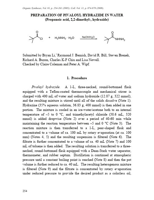
Organic Syntheses, Vol. 81, p. 254-261 (2005); Coll. Vol. 11, p. 874-878 (2009).254 PREPARATION OF PIVALOYL HYDRAZIDE IN WATER (Propanoic acid, 2,2-dimethyl-, hydrazide)2 +NaOH/H2OH2NNH2 · H2OSubmitted by Bryan Li,1Raymond J. Bemish, David R. Bill, Steven Brenek, Richard A. Buzon, Charles K-F Chiu and Lisa Newell.Checked by Claire Coleman and Peter A. Wipf.1. ProcedurePivaloyl hydrazide. A 1-L, three-necked, round-bottomed flask equipped with a T eflon-coated thermocouple and mechanical stirrer is charged with 400 mL of water and sodium hydroxide (12.87 g, 322 mmol), and the resulting mixture is stirred until all of the solids dissolve (Note 1). Hydrazine (35% aqueous solution, 36.83 g, 400 mmol) is then added in one portion. T he mixture is cooled in an ice-water/acetone bath to an internal temperature of –5 to 0 °C, and trimethylacetyl chloride (38.6 mL, 320 mmol) is added dropwise (Note 2) over a period of 40-60 min while maintaining the reaction temperature between –5 and 0 °C (Note 3). T he reaction mixture is then transferred to a 1-L, pear-shaped flask and concentrated to a volume of ca. 100 mL by rotary evaporation (at ca. 100 mm) (Notes 4, 5) and the resulting suspension is filtered (Note 6). T he filtrate is further concentrated to a volume of ca. 40 mL (Note 7) and 100 mL of toluene is then added. The resulting solution is transferred to a three-necked, round-bottomed flask equipped with a Dean-Stark water separator, thermometer, and rubber septum. Distillation is continued at atmospheric pressure until a constant boiling point is reached (Note 8) and then the pot volume is further reduced to ca. 40 mL. The resulting heterogenous mixture is filtered (Note 9) and the filtrate is concentrated by rotary evaporation under reduced pressure to provide the desired product as a colorless oil,255which on sta nding solidifies to a white semi-solid. This ma teria l is recrysta llized from 100 mL of isopropyl ether to a fford 18.6-20.4 g (50-55%) of pivaloyl hydrazide (Notes 10, 11).2. Notes1. All rea gents were purcha sed from Aldrich Chemica l Compa ny (except for trimethyla cetyl chloride, which the checkers obta ined from Acros) and were used without further purification. The checkers used a low temperature alcohol thermometer in place of a Teflon-coated themocouple. The third neck of the flask was left open to the atmosphere.2. A syringe pump was used for the addition of acid chloride in order to achieve a steady flow rate. The tip of the syringe needle (gauge 20) was submerged in the rea ction mixture. Dropwise a ddition of trimethyla cetyl chloride at 0-5 °C resulted in the immediate formation of a precipitate.3. The rea ction wa s complete a t the end of the piva loyl chloride addition. On 5-L or larger scale, the reaction was conducted at temperatures of 10-15 °C without loss of selectivity.4. A small a mount of hydrazine hydrate was present in the reaction mixture a t this point, but a sa fety eva lua tion indica ted the fina l rea ction mixture ha d a very low therma l potentia l (DH=15.3 J/g). This poses a minimum thermal hazard for vacuum distillation.5. The submitters concentra ted the rea ction mixture by va cuum distilla tion (100 mm, ba th tempera ture 70 °C, va por tempera ture 51 °C). The weight a fter concentra tion wa s ca. 120 g. The checkers used rota ry evaporation with a bath temperature of 65 to 70 °C without any problems, and employed an explosion shield as a safety precaution.6. The bis-a cyl a tion byproduct (Me 3CCONHNHCOCMe 3) w a s removed by filtration; 20 mL of water was used for washing the filter cake.7. The submitters removed solvent by vacuum distillation (100 mm, bath temperature 70 °C, vapor temperature 51 °C).8. Azeotropic remova l of wa ter wa s complete when the va por temperature reached 111 °C.9. Sodium chloride was removed by filtration.10.T he submitters obtained the product in 72% yield without recrystallization and determined the product to be >97% pure by HPLC (by area; conditions: 250 mm Kromasil C4 column using acetonitrile (A)/water(B) and 0.1% TFA in water (C), 0:90:10 A:B:C ramp to 90:0:10 A:B:C over15 min and hold for 5 min.Waste Disposal InformationAll toxic materials were disposed of in accordance with “Prudent Practice in the Laboratory”; National Academy Press; Washington, DC, 1995.3. DiscussionHydrazides (RCON HN H2) are highly useful starting materials and intermediates in the synthesis of heterocyclic molecules.2 They can be synthesized by hydrazinolysis of amides, esters and thioesters.3 The reaction of hydrazine with acyl chlorides or anhydrides is also well known,4 but it is complicated by the formation of 1,2-diacylhydrazines, and often requires the use of anhydrous hydrazine which presents a high thermal hazard. Diacylation products predominate when hydrazine reacts with low molecular weight aliphatic acyl chlorides, which makes the reaction impractical for preparatory purposes.5Recently we needed to prepare large amounts of pivaloyl hydrazide (1). A literature survey indicated several approaches: (1) heating pivalic acid with hydrazine hydrate with a Lewis acid catalyst such as activated alumina6 or titanium oxide;7 (2) heating hydrazine hydrate at high temperature (140 °C) with ethyl pivalate;8 (3) condensing phthaloyl hydrazine with pivaloyl chloride, followed by deprotection of the phthaloyl group;9 and (4) reaction of ethyl thiopivalate with hydrazine hydrate. Reaction safety evaluations revealed that hydrazine monohydrate has an onset temperature of ca. 125 °C in a Differential Scanning Calorimetry (DSC) experiment, and possesses a very high thermal potential ( H = 2500 J/g),10,11 which prompted us to develop a method for the synthesis of 1 that did not require heating. After some experimentation we determined that the reaction of pivaloyl chloride with hydrazine proceeds most efficiently in water to give a 4:1 ratio12 of 1 to Me3CCONHNHCOCMe3(2). The use of organic solvents (MeOH, THF, 2-propanol) with water13 invariably led to formation of biphasic mixtures and predominant formation of 2.14 Reaction workup is also simplified using256water as solvent. Upon partial concentration the bis-acylhydrazide byproduct 2precipitated out of the reaction mixture and is convenientlyremoved by filtration. Removal of the remainder of the water bydisplacement with toluene leads to precipitation of NaCl, which is alsoeasily removed by filtration. The filtrate is then further concentrated toprovide 1 in >97% purity, typically in 55–75% yield. This procedure hasbeen employed to prepare 10 Kg batches of 1 with no difficulty.译文:在水相中制备特戊酰氯 (丙酸,2,2-二甲基酰肼)论文由Bryan Li, Raymond J 、Bemish, David R 、Bill, Steven Brenek,Richard A 、Buzon, Charles K-F Chiu 和 Lisa Newell 等发表,经Claire Coleman 与Peter A. Wipf 审核。
一篇甲醇合成的外文文献原文
A New Low-Temperature Synthesis Route of Methanol:Catalytic Effect of the Alcoholic Solvent1. IntroductionGas-phase methanol is being produced industrially by 30-40 million ton per year around the world, from CO/ CO2/H2 at a temperature range of 523-573 K and a pressure range of 50-100 bar, using copper-zinc-based oxide catalyst. Under these extreme reaction conditions, the efficiency of methanol synthesis is severely limited by thermodynamics as methanol synthesis is an extremely exothermic reaction.1,2 For example, at 573 K and 50 bar, it is calculated by thermodynamics that theoretic maximum one-pass CO conversion is around 20% for flow-type reactor when H2/CO=2. Also it is reported that the one-pass CO conversion in the industrial ICI process is between 15 and 25%, even if H2-rich gas is used (H2/CO =5,523-573 K).3 Therefore, developing a low-temperature process for methanol synthesis, which will greatly reduce the production cost and utilize the thermodynamic advantage at low temperature, is challenging and important.3 If conversion is high enough in methanol synthesis, recycling of the unreacted syngas can be omitted and air can be used directly in the reformer, instead of pure oxygen. Generally, low-temperature methanol synthesis is conducted in the liquid phase.The BNL method first reported by Brookhaven National Laboratory (BNL), using a very strong base catalyst (mixture of NaH, acetate), realized this continuous liquid-phase synthesis in a semi-batch reactor at 373-403 K and 10-50 bar. However, a remarkable drawback of this process is that even a trace amount of carbon dioxide and water in the feed gas or reaction system will deactivate the strongly basic catalyst soon,4,5 resulting in high cost coming from the complete purification of the syngas from reformer, and reactivation of the deactivated catalyst. This is the main reason stopping the commercialization of this low-temperature methanol synthesis method.Liquid-phase methanol synthesis from pure CO and H2 via the formation of methyl formate has been widely studied, where carbonylation of methanol and successive hydrogenation of methyl formate were considered as two main steps of the reaction.6-13Palekar et al. used a potassium methoxide/copper chromite catalyst system to conduct this liquid-phase reaction in a semi-batch reactor at 373-453 K and 30-65 bar.6 Although the mechanism of BNL method is still controversial, a lot of researchers think that it is similar to the mechanism above.3 However, similar to that in the BNL method, in this process CO2 and H2O act as poisons to the strong base catalyst (RONa, ROK) as well and must be completely removed from syngas, making commercialization of low-temperature methanol synthesis difficult.Tsubaki et al. proposed a new method of low-temperature synthesis of methanol from CO2/H2 on a Cu-based oxide catalyst using ethanol as a kind of “catalytic solvent”, by which methanol was produced in a batch reactor at 443 K and 30 bar.14 This new process consisted of three steps: (1) formic acid synthesis from CO2 and H2; (2) esterification of formic acid by ethanol to ethyl formate; and (3) hydrogenation of ethyl formate to methanol and ethanol. Considering that the water-gas shift reaction at lower temperature is easily con-ducted on Cu/ZnO catalyst,15-25a new route of methanol synthesis from CO/H2 containing CO2, as a more practical way of methanol synthesis, is proposed. It consists of the following fundamental steps:As formic acid was not detected in the products, we suggested the reaction path as step (2). Tsubaki et al. investigated the synthesis reaction of methanol from CO/CO2/H2, using ethanol as reaction medium in a batch reactor and found high selectivity for methanol formation at temperature as low as 423-443 K.26In this communication, the catalytic promoting effects of different alcohols on the synthesis of methanol from CO/ CO2/H2 on Cu/ZnO catalyst were investigated. High yields ofmethanol were realized while some alcohols were utilized.2. Experimental SectionThe catalyst was prepared by the conventional coprecipitation method. An aqueous solution containing copper, zinc nitrates (Cu/Zn in molar ratio=1), and an aqueous solution of sodium carbonate were added simultaneously with constant stirring to 300 mL of water. The precipitation temperature and pH value were maintained at 338 K and 8.3-8.5, respectively. The resulting precipitate was filtrated and washed with distilled water, followed by drying at 383 K for 24 h and calcination at 623 K for 1 h. This precursor was then reduced by a flow of 5% hydrogen in nitrogen at 473 K for 13 h and successively passivated by 2% oxygen diluted by argon. The BET surface area for the catalyst was 59.4 m2/g. The catalyst here is denoted as Cu/ZnO (A).In the experiments using reactant gas of different composition, a commercially available ICI catalyst (ICI 51-2) was also used through the same reduction pretreatment, denoted here as Cu/ZnO (B). The BET surface area for Cu/ZnO (B) was 20.1 m2/g.To confirm the influence of the catalyst passivation, a tailor-made reactor where in situ reduction of the catalyst before ethanol introduction was available, was used to perform the catalyst reduction and reaction; but no difference in reaction behavior was observed. So using passivated catalyst reduced separately had no influence.In the reaction, a closed typical batch reactor with inner volume of 80 mL and a stirrer was used. The stirring speed of the propeller-type stirrer was carefully checked to eliminate the diffusion resistance between gas, liquid, and solid phases. A desired amount of solvent and catalyst was added into the reactor. Then the reactor was closed and the air inside the reactor was purged by reactant gas. A pressurized mixture gas of CO (31.90%), CO2 (5.08%), and H2 (60.08%) was introduced and then the reaction took place at the desired temperature. Ar of 2.94% in the feed gas was used as inner standard. After reaction, the reactor was cooled by ice-water and then the gas inside the reactor was released very slowly and collected in a gas-bag for analysis. The standard reaction conditions were as follows: catalyst=1.0 g; solvent=20 mL; reaction temperature=443 K; initial pressure=30 bar. At the standard reaction temperature of 443 K, the pressure was calculated to be 55 bar, including the vapor pressure of about 10 bar from ethanol.27All products were confirmed on GC-MS (Shimadzu GCMS 1600) and analyzed by two gas chromatographs (Shimadzu GC-8A/FID for liquid products, and GL Science GC-320/TCD for gas products). Conversion or yield was calculated on the basis of all carbon in the feed gas.In the experiments using reactant gas of different composition, where Cu/ZnO (B) was employed, a conventional magnetically stirred batch reactor was used. Thereaction conditions were: temperature=423 K; initial pressure=30 bar; reaction time =2 h; catalyst 0.2 g; alcohol (ethanol): 5 mL.3. Results and DiscussionThe analysis results showed that only CO and CO2 existed in the postreaction gas and only methanol and the corresponding HCOOR were the obtained liquid products. Table 1 listed the results of 13 kinds of alcohols used as reaction solvent separately under the same reaction conditions where Cu/ZnO (A) was employed. For comparison, the results in the cases of no solvent and cyclohexane were also listed in Table 1. The total conversion was the sum of the yields of both methanol and ester. From the table, no activity appeared when cyclohexane was used or no solvent was used. However, in most reactions, when alcohol was used, high activity was observed, suggesting the catalytic promoting effect of alcohol at low temperature. These alcohols lowered the reaction temperature significantly and accelerated the reaction, but did not affect stoichiometry of the overall reaction as in steps (1)-(3) listed above.For the six 1-alcohols from ethanol through 1-hexanol to benzyl alcohol, the conversions to methanol and the corresponding ester (HCOOR) decreased withincreasing carbon number of alcohol molecule. No ester was observed for these first alcohols when their carbon number was more than three. This is in accordance with the rate sequence of different 1-alcohols in the esterification reaction,28 providing the evidence that step (2) was rate-determining. As the concentration of ester, HCOOR, was so low, step (3) was believed to be quicker than step (2). It should be noted that, for all alcohols, they had a large molar ratio of ROH to the total carbon in the feed gas; the difference coming from the influence of molar numbers of different alcoholic solvents can be ignored.Concerning the alcohols with the same carbon number but different structure, the second alcohol had highest activity, as shown in the reactions in 2-propanol, 2-bu-tanol, and 2-pentanol separately. 2-Propanol exhibited highest activity among these three 2-alcohols. For example, at 443 K, the total conversion in the solvent of 2-propanol was high up to 23.46%, among which methanol and 2-propyl formate yields accounted for 13.19% and 10.27%, respectively.For alcohols with larger spatial obstacle, the reaction had lower activity, as shown in the cases of iso-butanol, tert-butyl alcohol, and cyclopentanol. In addition, for ethylene glycol and benzyl alcohol, no activity was observed. But the reason is not very clear now.On the reasons for different behaviors of the alcohols with the same carbon number but different structure, it is considered that different alcohol type affected step(2) by both the electronic effect and spatial effect. For 1-butanol, the electron density of oxygen atom in ROH is lower. As a result, ROH attacked the carbon atom of HCOOCu, the intermediate of step (2), more slowly. But the spatial obstacle of 1-butanol is the smallest among all butanols, and this is favorable to the nucleophilic attack in the esterification reaction. On the other hand, iso-butanol has high electronic density in its oxygen atom and this should accelerate the reaction. But its large molecular volume became a severe spatial obstacle in the nucleophilic attack. So its esterification rate was low. As a balanced effect between electronic factor and spatial factor, 2-butanol exhibited highest activity among 4 butanols, in the rate-determining step (2). As the opposite example, tert-butyl alcohol gave the yield of methanol as low as 5.83% here.It should be pointed out that the accumulated ester (HCOOR) can be easily transferred to methanol and ROH under higher H2 partial pressure. Two experiments were conducted to demonstrate this. One was the hydrogenation of ethyl formate in a batch reactor and the other was the hydrogenation of 2-butyl formate in a flow-type semi-batch autoclave reactor. For the first one, the reaction conditions were similar to those used in the synthesis reaction of methanol described above. A mixture gas of H2 and N2 with a total initial pressure of 30 bar (20 bar H2 and 10 bar N2) was used as feed gas. Ethyl formate (1.5 mL) and 18.5 mL of cyclohexane were mixed and poured into the reactor instead of 20 mL of alcohol. After 2 h reaction, the totalconversion of ethyl formate was 98.20% and the yield of methanol was 83.69%. Methyl formate and CO were byproducts. Methyl formate might come from the transesterification of ethyl formate and the methanol produced. CO might come from the decomposition of ethyl formate. For the latter experiment, 7.5 mL of 2-butyl formate (5 times amount in volume of ethyl formate used in the first experiment) and 12.5 mL of cyclohexane were poured in the reactor. A flow of pure H2 (20 mL/min, 30 bar) was used as flowing gas. After 8 h continuous reaction at 443 K, 96.23% of 2-butyl formate was transferred to methanol and 2-butanol.The total conversions were high while 2-alcohols were utilized. But the yields to ester were also high, especially for 2-pentanol. It is referred that step (3) above was slower if 2-alcohols were used. In other cases, the rate of step (3) was much faster than that of step (2), resulting in the disappearance or very low yield of the corresponding esters.If the water was added to ethanol with the same molar amount as that of CO2 in the feed gas under standard conditions, and the same experiment was conducted, similar results were obtained. Water did not affect the reaction behavior at these reaction conditions. From the reaction mechanism above, water was only an intermediate, similar to the role of CO2 in steps (1)-(3).In Table 2, the influence from various reactant gas composition was investigated at 423 K where catalyst Cu/ZnO (B) was used. It is clear that the total reaction rate increased with the increasing of CO2 content in the syngas. The reaction of CO2 +H2 exhibited the highest reaction rate. It seems that methanol synthesis rate was faster from CO2+H2 than from CO+H2, supporting that step (1) in the reaction mechanism was reasonable. It is interesting that pure CO did not react, indicating carbonylation of alcohol to ester impossible. While using pure CO +H2 as reactantgas, ethyl formate formed but methanol was not obtained. The reaction rate was rather lower than that of CO2-contained syngas. It is hard to determine the reaction route of pure CO +H2 now, as CO insertion to ethanol to form an ester was excluded. Maybe water contained in the ethanol (about 100-150 ppm) reacted with CO to form CO2 and fulfilled steps (1) and (2).4. ConclusionsThe use of alcohol, especially 2-alcohols, as a catalytic solvent in the synthesis of methanol from CO/CO2/H2, not only realized a new low-temperature methanol synthesis method, but also overcame drawbacks of the BNL method and other low-temperature methanol synthesis methods. This effect from accompanying alcoholic solvent decreased greatly the temperature and pressure of the synthesis reaction on Cu/ZnO solid catalyst, via a new reaction path. This method is very promising to become a new technology for low-temperature methanol synthesis where purification of syngas is not necessary. Since the reaction employed conventional solid catalyst, very mild reaction conditions, and syngas containing CO2 and H2O, it might be a promising practical method for methanol synthesis at low temperature.In fact, when the amount (weight) of catalyst was increased, the conversion was increased linearly in our experiments. 50-60% conversion was realized in a flow-type semi-batch reactor, as low-temperature methanol synthesis has no thermodynamic limitation. But in the high-temperature reaction, even the catalyst weight is enhanced, conversion cannot be increased due to intrinsic thermodynamics limitation.In the future, a bubble-column reactor is considered for large-scale synthesis. AcknowledgmentResearch for Future Program from Japan Society for the Promotion of Science (JSPS) is greatly acknowledged (JSPS-RFTF98P01001). EF0100395 References[1]Herman, R. G.; Simmons, G. W.; Klier, K. Stud. Surf. Sci. Catal.1981, 7, 475.[2]Graaf, G. H.; Sijtsema, P.; Stamhuis, E. J.; Oosten, G. Chem.Eng. Sci. 1986, 41, 2883.[3]Marchionna, M.; Lami, M.; Galleti, A. CHEMTECH, 1977, April,27.[4]Haggin, J. Chem. Eng. News 1986, Aug. 4, 21.[5]Brookheaven National Laboratory, U.S. Patents, 4,614,749, 4,-619,946, 4,623,634, 4,613,623 [1986], 4,935,395 [1990].[6]Palekar, V. M.; Jung, H.; Tierney, J. W.; Wender, I. Appl. Catal.1993, 102, 13.[7]Kirk-Othmer. Encyclopedia of Chemical Technology, 2nd ed.;Wiley: New York, 1964; V ol. 13, p 390.[8]Palekar, V. M.; Jung, H.; Tierney, J. W.; Wender, I. Appl. Catal.1993, 103, 105.[9]Wender, I. Fuel Process. Technol. 1996, 48, 189.[10]Onsager, O. T. World Patent 86/03190, 1986.[11] Zhang, H.; Li, H.; Lin, G.; Tsai, K. R. Stud. Surf. Sci. Catal.1996, 101, 1369.[12]Chen, Y. Z.; Chung, B. Z.; Hsieh, C. R. Catal. Lett. 1996, 41,213.[13]Girolamo, M.; Marchionna, M. Ital. Patent MI92/A 002126, 1992[14]subaki, N.; Sakaiya, Y.; Fujimoto, K. Appl. Catal. 1999, 180,L11.[15]Chen, C. S.; Cheng, W. H.; Lin, S. S. Catal. Lett. 2000, 68, 45.[16]Yoshihara, J.; Campbell, C. T. J. Catal. 1996, 161, 776.[17]Fujita, S.; Usui, M.; Ito, H.; Takezawa, N. J. Catal. 1995, 157,403.[18]Bailey, S.; Fromont, G. F.; Snoeck, J. W.; Waugh, K. C. Catal.Lett. 1995, 30, 99.[19]Yoshihara, J.; Parker, S.; Schafer, A.; Campbell, C. T. Catal.Lett. 1995, 31, 313.[20]Oki, S.; Happel, J.; Hnatow, M.; Kaneko, Y. Proc. 5th Int. Congr.Catal. 1973, 1, 173.[21]Oki, S.; Mezaki, R. J. Phys. Chem. 1973, 77, 447; 1973, 77, 1601.[22]Mezaki, R.; Oki, S. J. Catal. 1973, 30, 488.[23]Shchibrya, G. G.; Morozov, N. M.; Temkin, M. I. Kinet. Katal.1965, 6, 1115.[24]Uchida, H.; Isogai, N.; Oba, M.; Hasegawa, T. Bull. Chem. Soc.Jpn. 1967, 40, 1981.[25]Yureva, T. M.; Boreskov, G. K.; Gruver, V. S. Kinet. Katal. 1969,10, 862.[26]Tsubaki, N.; Ito, M.; Fujimoto, K. J. Catal. 2001, 197, 224.[27]Perry, F.; Chilton, T. Chemical Engineers’ Handbook, 5th ed.;McGraw-Hill: New York, 1975; pp 3-62.[28]Morrison, R. T.; Boyd, R. N. Organic Chemistry; Allyn andBacon: Boston, MA, 1973; Chapter 20.。
甲醇生产英语文献
Energy savings by co-production:A methanol/electricity case studyLiu Guang-jian a,b ,Li Zheng b,*,Wang Ming-hua b ,Ni Wei-dou ba School of Energy and Power Engineering,North China Electric Power University,Beijing 102206,China bState Key Lab of Power Systems,Dept.of Thermal Engineering,Tsinghua University,Beijing 100084,Chinaa r t i c l e i n f o Article history:Received 28February 2009Received in revised form 12August 2009Accepted 20August 2009Available online 23September 2009Keywords:Co-production system Coal gasification Exergy analysisEnergy-saving factora b s t r a c tThe overall exergy losses of co-production systems were decomposed into five sub-systems:chemical reaction processes,heat exchange processes,external exergy losses,turbine/mechanical exergy losses and others.By defining new parameters called energy-saving factors,we quantitatively describe the con-tribution of these processes to the overall energy savings relative to separate production systems.A methanol/electricity co-production system is taken as case study,results show that heat exchange pro-cesses are the main contribution to the energy savings.Ó2009Elsevier Ltd.All rights reserved.1.IntroductionCoal gasification based co-production systems have captured the interest of many researchers as promising alternatives for the simultaneous production of electricity,synthetic liquid fuels,hydrogen or chemicals [1–3].Through mass and energy integration between chemical production process and the power generation process,such systems could allow for considerable savings in investment cost,improved energy efficiency and savings in the cost of capturing CO 2[4–6].However,because of multi-products and complex material and energy integration in co-production sys-tems,it needs suitable efficiencies or others indicators of the en-ergy performance,to gain insight into the reason for the energy benefits and contribute to the development of optimized energy conversion systems.Larson and Ren [7]report detailed process designs and cost assessments for liquid fuels (methanol and dimethyl ether)by indirect coal liquefaction.The authors introduced methanol (or dimethyl ether)and electricity co-production systems.An effective methanol (or dimethyl ether)energy conversion efficiency and the fraction of coal LHV converted to products (chemical and electric-ity)were used as energy performance indicators.Ma et al.[8]pre-sented preliminary energy analysis of different configurations of methanol/IGCC co-production systems.The authors use total first law thermal efficiency as evaluation criteria to compare different co-production systems,and find that the higher ratio of chemical energy output/electricity output,the higher the total first law ther-mal efficiency.Duan et al.[9]report exergy analysis of methanol/IGCC co-production plant.The whole system was divided into five sub-systems:gasification,cleanup,synthesis,exhaust heat and power generation.The exergy loss in power generation and gasifi-cation are the biggest.Lin et al.[10]has defined a criterion for en-ergy saving ratio for methanol and electricity co-production systems that is similar to a measure of primary energy savings defined by Gianfranco and Pierluigi [11].From the literature review,we can see that the previous energy and exergy analyses of co-production systems mainly have focused on the component level (such as gasification section,chemical syn-thesis section,power island section,and so on)or on the whole system level.The main evaluation indices are total first law effi-ciency,total exergy efficiency,an effective chemical production efficiency,or relative primary energy savings.However,because of the complex material and energy integration in typical co-pro-duction systems,it is difficult to isolate,for purposes of quantita-tive analysis,all processes ongoing in a specific section.In this context,we develop in this paper a new evaluation crite-ria –energy-saving factor,to provide further insight into the energy and exergy losses in co-production systems.Methanol and electricity co-production system is used for illustration.2.Exergy loss decomposition model of co-production system Fig.1shows that,compared with separate systems,co-produc-tion systems involve some integration of material flows and energy flows,such as:unconverted gas is sent to the power island for combustion (sometimes with partial recycling);steam from the HRSG is used for reboiler duty in the distillation section,etc.0306-2619/$-see front matter Ó2009Elsevier Ltd.All rights reserved.doi:10.1016/j.apenergy.2009.08.036*Corresponding author.Tel.:+861062795735.E-mail address:lz-dte@ (Z.Li).Applied Energy 87(2010)2854–2859Contents lists available at ScienceDirectApplied Energyj o ur na l h o me pa ge :w w w.e ls e v ie r.c o m/lo c a t e/ap en e rgyFor a co-production system like that shown in Fig.1(top),we can write the exergy balance equation for the system:E coalþE air1þE wtþE air2¼E mþE pþE ashþE acid-gasþE flue-gasþE N2þIr1þIr2þIr3þIr4þIr5ð1Þwhere E coal,E air1,E wt,and E air2are the exergy of input stream mate-rialflows(coal,air for air separation unit,water for coal gasification, and air for gas turbine);E m,E p,E ash,E acid-gas,Eflue-gas,and E N2are the exergy of output stream materialflows(methanol,electricity,nitro-gen vent,ash and slag,acid-gas,andflue-gas);and Ir1–Ir5are the irreversibility of gasification subsystem,methanol synthesis sub-system,product separation subsystem,gas turbine subsystem, HRSG/steam turbine subsystem.Eq.(1)can be rewritten into Eq.(4)by Eqs.(2)and(3).E ext-loss¼E N2þE ashþE acid-gasþE flue-gasÀE air1ÀE wtÀE air2ð2ÞXIr¼Ir1þIr2þIr3þIr4þIr5ð3ÞE coal¼E mþE pþXIrþE ext-lossð4ÞG.-j.Liu et al./Applied Energy87(2010)2854–28592855where we define E ext-loss to be the net external stream exergy loss;PIr is total internal exergy loss in co-production system.In order to distinguish the contribution of different types of en-ergy conversion processes ongoing in the system,PIr is decom-posed into exergy losses from (1)chemical reaction processes (including gasification reaction,methanol synthesis process,com-bustion process),(2)heat exchange processes,(3)turbine/mechan-ical exergy losses,and (4)other exergy losses (including mixing processes,separation processes,etc.).XIr ¼Ir ch þIr hx þIr ph þIr others ð5ÞFor separate power and methanol production systems,we can get similar exergy balance equations.For stand-alone methanol production system producing the same amount of methanol as in our co-production system:E coal1¼E m þIr ch-1þIr hx-1þIr ph-1þIr others-1þE ext-loss-1ð6ÞFor stand-alone power generation using IGCC producing the same amount of power as in our co-production system:E coal2¼E p þIr ch-2þIr hx-2þIr ph-2þIr others-2þE ext-loss-2ð7ÞA fuel exergy saving ratio then can be calculated:D E coal ¼E coal 0ÀE coalE coal 0¼D Ir ch E coal 0þD Ir hx E coal 0þD Ir ph E coal 0þD Ir others E coal 0þD E ext-loss E coal 0ð8ÞwhereE coal 0¼E coal1þE coal2;D Ir X ¼ðIr X À1þIr X À2ÞÀIr X ;D E ext-loss ¼ðE ext-loss-1þE ext-loss-2ÞÀE ext-loss :If we define the individual terms on the right side of Eq.(7)as:Factor 1¼D Ir ch coal 0;Factor 2¼D Ir hx coal 0;Factor 3¼D Ir ph coal 0;Factor 4¼D Ir othersE coal 0;Factor 5¼D E ext-lossE coal,then Factor 1–Factor 5represent the contributions of different types of irreversibilities to the exergy savings of co-production versus stand-alone production systems.We can name Factor 1–Factor 5the energy-saving factors of differ-ent types of process ongoing in a co-production system.Through calculation and analysis of energy-saving factors,we can describe the distribution of exergy loss in the co-production system and reveal the essence of energy saving.3.Case study of co-production system and separate production systemsFig.2shows the case study of methanol and electricity co-pro-duction system we analyze quantitatively here.Co-production plants can have different configurations than the one analyzed here and energy performance results will differ accordingly [12].The ratio of chemical to electrical product in particular can strongly affect the overall energy performance comparison.However the same approach and evaluation indices in this paper can be used to analyze any plant configuration.The clean syngas after gasification is separated into two parts:one is sent to methanol synthesis section;the other part,combined with unconverted gas from methanol synthesis and separation unit is sent to a power island to generate electricity.The system use a liquid phase methanol (LPMEOH TM )process,which uses a slurry bubble column reactor and can directly process syngas that is rich in carbon oxides (carbon monoxide and carbon dioxide),as pro-duced by oxygen-blown gasification of coal.Thus,there is no need for a water gas shift reactor to adjust syngas composition between the gasifier and the synthesis reactor.The clean syngas sent to methanol synthesis is passed once over the synthesis catalyst,with unconverted synthesis gas used to generate electricity in a gas tur-bine combined cycle.This design does not maximize liquid fuel production,but provides for a significant second revenue stream from sale of electricity.The main stream and energy integration in-volves steam recovery from gasification section and methanol syn-thesis section for integration with power island;the unconverted gas from methanol synthesis section is used as the fuel gas to gas turbine.In order to compare energy performance between different systems,we define a separate electricity generation system –IGCC based on GE quench mode gasifier (IGCC-Quench),and sep-arate methanol production system based on Lurgi gas phase methanol synthesis reactor (GPMEOH).The detail simulation re-sults can ben seen in Ref.[13].The coal compositionalanalysisTable 1Compositional characteristics of Yanzhou coal.Proximate analysis (wt.%,as-received)Ultimate analysis (wt.%,dry)Moisture 5.81ASH 7.53Fixed carbon 49.85Carbon 73.64Volatile matter 37.24Hydrogen 5.24ASH7.09Nitrogen 1.13HHV (kJ/kg,dry)28,526Sulfur 2.63Oxygen9.832856G.-j.Liu et al./Applied Energy 87(2010)2854–2859and the key process operation parameters are shown in Tables1 and2.4.Results and discussionTable3shows a comparison of the exergy efficiencies and exer-gy loss distribution between the separated systems and the co-pro-duction system.The total exergy efficiency of co-production system is47%, which is in between that of the IGCC system(39%)and the methanol production system(54%).The exergy losses of gasification and combustion are the big-gest in three systems,accounting for16%in stand-alonemethanol system to30%in IGCC system of input coal exergy, the reason is high irreversiblities in heat transfer between product molecules and reactant molecules and chemical reactions(gasification and combustion)of gasifier and gas turbine combustor(or boiler in stand-alone methanol sys-tem)units,which are in principle avoidable.The second biggest losses are heat exchange processes, accounting for10%in co-production system to12%in sepa-rated systems of input coal exergy.If the output of electricity and methanol is the same for separate and co-production systems,the total fuel exergy saving ratio is 7.1%(see Fig.3).Chemical reaction processes and heat exchange processes are the biggest contributors.In chemical reaction pro-cesses,the energy-saving factor is2.6%,accounting for36.4%of the total fuel saving ratio;in heat exchange processes,the en-ergy-saving factor is2.5%,accounting for35.2%of the total fuel saving ratio.Other energy-saving factors are relatively small,less than1.0%.Therefore the main energy saving sources is from chem-ical reaction and heat exchange processes.Further analysis of these two sub-systems is highlight in the next section.Table2Reference operating parameters of the co-production systems.Section Technology Parameter(unit)ValueGasificationprocess Entrained-flow gasifier(GE-Quench)Pressure(MPa) 4.0/7.0*Gasificationtemperature(°C)1300Slurry solid density66.5%Carbon conversionratio98%Methanolsynthesisprocess Gas phase methanolsynthesis(stand-alonesystem)Pressure(MPa) 5.0Temperature(°C)250Recycle ratio 4.5 Liquid phase methanolsynthesis(co-production system)Pressure(MPa) 6.5Temperature(°C)250Recycle ratio0Power island Gas turbine(based onSiemens V94.3)Pressure ratio16.1 Turbine inlettemperature(°C)1340Exhaust gastemperature(°C)576HRSG&steam cycle (from literature[8])Pinch temperature(°C)15 Approachtemperature(°C)15 Exhaustflue-gas temperature(°C)110*For IGCC,the pressure is4.0MPa;for methanol production and co-productionsystem,it is7.0MPa.Table3Exergy losses and exergy efficiency comparison between separated system and co-production system when T o=298.15K and P o=101.3kPa.Stand-alone power(IGCC)Stand-alone methanol(GPMEOH)Co-productionkJ/kg-coal Ratio(%)kJ/kg-coal Ratio(%)kJ/kg-coal Ratio(%) Coal input29,051100.029,051100.029,051100.0Exergy lossesChemical reactionGasification402213.8362312.5392213.5 Combustion485016.7919 3.2337211.6 Shift reaction––1740.60.000.0 Methanol synthesis––355 1.21430.5 External exergyflows*1738 6.01769 6.11744 6.0 Heat exchange336811.6354511.928899.9 Air separation unit**847 2.91393 4.8879 3.0 Turbine/mechanical25248.71016 3.520217.0 Others414 1.4567 2.0403 1.4Sum17,76361.113,26845.715,37152.9OutputMethanol––15,78354.3540918.6Net electricity11,28838.9––827028.5 Total exergy output11,28838.915,78354.313,67947.1*This is the net exergy of streamflows into and out of the system.**The air separation unit is not simulated but taken as a separate process for simplification.G.-j.Liu et al./Applied Energy87(2010)2854–285928574.1.Energy-saving analysis of reaction sub-systemsThe chemical reaction processes in co-production system in-cludes four parts:coal gasification,water–gas shift reaction(shift reaction),methanol synthesis,and combustion.For the gasification process,the small benefit in exergy effi-ciency is due to the higher gasification pressure used in the co-production system compared with the low gasifier pres-sure in the IGCC[14].No shift reaction is needed to change the syngas H2/CO ratio in the co-production system,but shift reaction process is a relatively efficient process,1so the exergy gain due to lack of shift reaction is small(about0.19%).For methanol synthesis process,it is interesting that the exergy loss of co-production system is higher than that of the separate processes.The reason is that the CO conversion in the LPMEOH process is only20.3%,while it is97%for GPMEOH process due to recycling of unconverted syngas.Assuming the same methanol output,because of heat exchange between the unconverted syngas and products in the methanol synthesis reactor,the exergy loss per kg MeOH of the co-production system is larger than that of the stand-alone methanol system.For combustion process,the energy-saving factor is1.59%, second only to heat exchange processes.But this does not mean the exergy loss in combustion process can be decreased,it is still the second biggest exergy loss source in co-production system,see Table3.It can be explained that due to the heat integration between power island and chem-ical production process,the power output from steam tur-bine is relatively larger than that without heat integration.We use the power ratio of steam turbine to gas turbine(c) to reflect the effect of heat integration:the value of c in co-production system is0.79,while it is only0.65for weighted average of separate systems(the value of c in IGCC plant is about0.6[15]and it is1for stand-alone methanol system).This means that if total power output is the same for the co-production system and separate systems,the GT power output in co-production system is smaller than that of the separate systems,leading to less exergy loss in com-bustion process.4.2.Energy-saving analysis of heat exchange processThe heat exchange processes are characterized by the biggest energy-saving factor.The different heat exchange processes can be divided into two types.One is essential heat exchangers which are required to fulfill energy conversion tasks,such as waste heat boilers,the gasifier quench process,and heat loss in condenser cooling system.The other is the heat exchangers which are used to reduce the additional exergy losses with unmatched heat ex-change processes,such as the methanol synthesis reaction heat can be used to generate saturated steam that can be superheated in the gas turbine combined cycle section of the co-production plant;or the saturated steam can be used for methanol distillation unit at the stand-alone methanol production plant.With the same products output,Fig.4shows the exergy loss ratio of co-production and separate systems.Here the exergy loss ratio means the ratio of exergy losses of different heat exchange processes to coal exergy input.As can be seen,the exergy loss ratio of the second class of heat exchange processes decreases by1.34%, which accounts for54%of the total difference in exergy loss ratio of heat exchange processes between co-production and stand-alone systems.The main reason is that high heat integration potential in co-production system than that of stand-alone systems,such as no synthesis or shift reaction heat to be recovered in stand-alone power system and less high-temperature heat available(from combustion of the purge gas thatfire the power island)in stand-alone methanol system,which can be revealed by the ratio of the steam turbine to gas turbine output in the co-production and stand-alone systems.1In stand-alone methanol system,about55%coal derived syngas is needed to besent to shift reactor to adjust the H2/CO ratio from0.62to2.38by the water shiftreaction:CO+H2O vap?CO2+H2+44.477MJ/Mol CO.(i)The two moles on the lefthand side(CO+H2O vap)exhibit an exergy of287.14MJ,while the exergy of the twomoles on the right hand side(CO2+H2)is258.63MJ.(ii)The heat developed in thereaction—at the reference temperature of25°C,44.477MJ/Mol CO(assume shiftreactor is operated at constant temperature350°C,the exergy of reaction heat isabout23MJ/Mol CO)—can be recovered in the steam cycle.2858G.-j.Liu et al./Applied Energy87(2010)2854–28595.Summary and conclusions(1)In our analysis,exergy loss in co-production systems isdivided according to different processes:chemical reaction processes,heat exchange processes,external exergyflows losses,turbine/mechanical exergy losses,and other exergy losses.We defined the energy-saving factors,which can be used for quantitative description of the effects of different processes to the total energy saving ratio.(2)For the case study of methanol and electricity co-productionsystem we analyzed,the total exergy efficiency is47%,which unsurprisingly is in between that of IGCC system(39%)and stand-alone methanol production system(54%).The exergy losses of gasification and combustion are the biggest in three systems,because of high irreversiblities in internal thermal energy exchange and chemical reactions(gasification and combustion)of gasifier and gas turbine combustor(or boiler in stand-alone methanol system)units,which are in princi-ple avoidable.(3)With the same product outputs,the total coal exergy savingratio of the case study co-production system is7.1%.The big-gest energy-saving factor is associated with heat exchange processes,accounting for35%of the total coal exergy sav-ings;the next is the energy-saving factor of combustion pro-cess,accounting for22%of the total coal exergy saving.The ratio of steam turbine output to gas turbine output in co-production system is0.79,about20%higher than for an IGCC system,which reflects the heat integration of the whole system.(4)Co-production plants can have different configurations thanthe one analyzed here will have different energy perfor-mance results.Particularly,the ratio of chemical product and electricity can strongly affect the overall energy perfor-mance comparison.However the same approach and evalu-ation indexes in this paper can be used for analysis different plant configuration.AcknowledgementThis work is supported by the special fund of the national prior-ity basic research program(No.2005CB221207).We gratefully acknowledge Dr.Eric rson at Princeton University for instruc-tion on the editorial organization of the paper and discussion on the energy saving analysis section.References[1]Ni Wei-dou,Li Zheng.The ultra-clean utilization of coal-polygenerationsystem.Energy Conserv Environ Protect2001;5:16–21[in Chinese].[2]Hetland Jens,Zheng Li,Shisen Xu.How polygeneration schemes may developunder an advanced clean fossil fuel strategy under a joint sino-European initiative.Appl Energy2009;86:219–29.[3]Yamashita Kei,Barreto Leonardo.Energyplexes for the21st century:coalgasification for co-producing hydrogen,electricity and liquid fuels.Energy 2005;30:2453–73.[4]Lin Ru-mou,Jin Hong-guang,Gao Lin.The integration and optimizationmechanism of co-production system.J Eng Therm Energy Power 2006;21(4):331–7[in Chinese].[5]Jin Hong-guang,Gao Lin,Zheng Dan-xing,et al.Investigation of coal-based co-production system for power and chemical production.J Eng Thermophys 2001;22(4):397–400[in Chinese].[6]Wang Zhifang,Zheng Danxing,Jin Hongguang.Energy integration of acetyleneand power polygeneration byflowrate-exergy diagram.Appl Energy 2009;86(3):372–9.[7]Larson ED,Ren Ting-jin.Synthetic fuel production by indirect coal liquefaction.Energy Sustain Dev2003;VII(4):79–102.[8]Ma Lin-wei,Ni Wei-dou,Li Zheng,Ren Ting-jin.Analysis of the co-productionsystem of methanol and electricity based on coal gasification.Power Eng 2004;24(3):451–6[1,in Chinese].[9]Duan Yuanyuan,Zhang Jin,Shi Lin,et al.Exergy analysis of methanol-IGCCpolygeneration technology based on coal gasification.Tsinghua Sci Technol 2002;7(2):190–3.[10]Lin Gao,Hongguang Jin,Zelong Liu,Danxing Zheng.Exergy analysis of coal-based co-production system for power and chemical production.Energy 2004;29:2359–71.[11]Gianfranco Chicco,Pierluigi Mancarella.A unified model for energy andenvironmental performance assessment of natural gas-fueled poly-generation systems.Energy Convers Manage2008;49:2069–77.[12]Gao Lin.Investigation of coal-based polygeneration systems for production ofpower and liquid fuel.Ph.D.Dissertation.Beijing:Institute of Engineering Thermophysics,Chinese Academy of Sciences;2005[in Chinese].[13]Liu Guangjian.Study on energy saving performance analysis andcomprehensive evaluation method of polygeneration system.Ph.D.Dissertation.Tsinghua University;2007[in Chinese].[14]Prins MJ,Ptasinski KJ.Energy and exergy analyses of the oxidation andgasification of carbon.Energy2005(30):982–1002.[15]National Energy Technology Laboratory.Cost and performance baseline forfossil energy plants.Bituminous coal and natural gas to electricityfinal report, vol.1.DOE/NETL-2007/1281;May2007.G.-j.Liu et al./Applied Energy87(2010)2854–28592859。
英文-甲醇
2002-01-2743 High Efficiency and Low Emissions from a Port-InjectedEngine with Neat Alcohol Fuels Matthew Brusstar, Mark Stuhldreher, David Swain and William PidgeonU. S. Environmental Protection Agency Copyright © 2002 Society of Automotive Engineers, Inc.ABSTRACTOngoing work with methanol- and ethanol-fueled engines at the EPA’s National Vehicle and Fuel Emissions Laboratory has demonstrated improved brake thermal efficiencies over the baseline diesel engine and low steady state NOx, HC and CO, along with inherently low PM emissions. In addition, the engine is expected to have significant system cost advantages compared with a similar diesel, mainly by virtue of its low-pressure port fuel injection (PFI) system. While recognizing the considerable challenge associated with cold start, the alcohol-fueled engine nonetheless offers the advantages of being a more efficient, cleaner alternative to gasoline and diesel engines.The unique EPA engine used for this work is a turbocharged, PFI spark-ignited 1.9L, 4-cylinder engine with 19.5:1 compression ratio. The engine operates unthrottled using stoichiometric fueling from full power to near idle conditions, using exhaust gas recirculation (EGR) and intake manifold pressure to modulate engine load. As a result, the engine, operating on methanol fuel, demonstrates better than 40% brake thermal efficiency from 6.5 to 15 bar BMEP at speeds ranging from 1200 to 3500 rpm, while achieving low steady state emissions using conventional aftertreatment strategies. Similar emissions levels were realized with ethanol fuel, but with slightly higher BSFC due to reduced spark authority at this compression ratio. These characteristics make the engine attractive for hybrid vehicle applications, for which it was initially developed, yet the significant expansion of the high-efficiency islands suggest that it may have broader appeal to conventional powertrain systems. With further refinement, this clean, more efficient and less expensive alternative to today’s petroleum-based IC engines should be considered as a bridging technology to the possible future of hydrogen as a transportation fuel.INTRODUCTIONAlternative fuels, especially alcohol fuels, offer potential to mitigate national security and economic concerns over fuel supplies as well as environmental concerns over tailpipe emissions and resource sustainability. As a result, there has been continuing interest in alternative fuels, heightened recently over proposed legislation that would mandate increases in the use of renewable transportation fuels. Over the last thirty years of automotive research, a variety of alcohol fuels—primarily methanol, ethanol and blends with hydrocarbon fuels—have demonstrated improved emissions of oxides of nitrogen (NOx) and particulate matter (PM) as well as moderately improved brake thermal efficiency [1-4]. Despite this, infrastructure barriers as well as technical challenges, notably cold starting, have limited the widespread use of neat alcohol-fueled vehicles.The benefits and challenges of neat alcohol fuels in PFI applications have been demonstrated in numerous earlier works. Benefits such as higher efficiency and specific power and lower emissions may be realized with alcohols: their high octane number gives the ability to operate at higher compression ratio without preignition [5]; their greater latent heat of vaporization gives a higher charge density [1-3, 6]; and their higher laminar flame speed allows them to be run with leaner, or more dilute, air/fuel mixtures [7]. In addition, alcohols generally give lower fuel heat release rates, resulting in lower NOx emissions and reduced combustion noise [2]. The engine described in the present work uses these inherent advantages of alcohol fuels as the basis for its design and control, thereby enabling attainment of efficiency levels exceeding that of the diesel, with low emissions.One of the main challenges with neat alcohol fuels is cold start emissions, especially in PFI engines [8]. In such applications, the low vapor pressure and lowcetane number must be overcome with higher-energy ignition systems or higher compression ratio [9]. Further, the increased wetting of the intake manifold, cylinder walls and spark plugs must be addressed in the design of the combustion chamber and in the control of transient fueling during startup [8, 10]. Because of these issues, earlier works with PFI SI methanol engines commonly report starting problems below ambient temperatures of about 10o C [8, 11]. With extended periods of cold cranking (i.e., 60 seconds or more), successful starting has been achieved at ambient temperatures as low as –6.5o C [12]. However, these studies were generally performed with lower compression ratio engines, derived from their gasoline counterparts, which are therefore not necessarily optimized for use with neat alcohol fuels. The ongoing work at EPA with high-compression ratio single cylinder PFI SI engines [13], for example, demonstrates the ability to fire on neat methanol during relatively brief cranking at higher speeds, at temperatures as low as 0o C.Earlier work at EPA with alcohol-fueled multi-cylinder engines examined both PFI and DI configurations, generally demonstrating improvements in fuel economy and power, as well as promising cold start emissions. Initial work with a methanol-fueled PFI SI engine [14, 15] yielded fuel economy and emissions that were similar to, but not significantly better than, the baseline gasoline engine. Cold starting was not addressed in that early program, but was instead examined in a follow-on project with a turbocharged, DI, glow-plug-ignited, stratified charge engine [16], based on earlier works showing good cold start performance down as low as –29o C [17]. This project was largely successful, demonstrating good startability and driveability down to –29o C, and producing low FTP emissions of NOx (0.3 g/mi), HC (<0.01 g/mi), CO (0.2 g/mi), PM (0.02 g/mi) and aldehydes (0.002 g/mi) while running lean with a single-stage oxidation catalyst. The measured fuel economy was between 7%-22% better than the baseline gasoline engine, but still slightly lower than the turbocharged diesel.The ongoing PFI alcohol work presented here builds on our earlier experience, and demonstrates better steady state efficiency than the baseline diesel and low emissions with conventional aftertreatment systems, at a significantly lower cost than the diesel. The engine described below runs unthrottled over most of its load range, much like the diesel, but operates with high EGR dilution ratios at stoichiometric fueling, rather than lean and stratified. This strategy takes advantage of the favorable dilute flammability limits of alcohol fuels to operate with lower pumping losses, and uses the high levels of EGR to control knock at high compression ratio. As a result, the engine demonstrates its potential as an efficient, lower cost, renewable fuels alternative to the diesel.EXPERIMENTAL SETUPThe research described below is being conducted under EPA’s Clean Automotive Technology Program, in order to demonstrate feasibility of cleaner, more efficient technologies. The primary focus of the work is on methanol fuel, since it represents the limiting case of oxygenated fuels, at 50% oxygen by mass. Also, its physical properties lend some performance advantages over other alcohols, discussed below. For comparison, however, brake thermal efficiency data with ethanol fuel is also given below, demonstrating similar benefits. ENGINE AND TEST DESCRIPTIONThe engine designed for this work is derived from the 1.9L Volkswagen TDI automotive diesel engine, modified suitably to accommodate port fuel injectors and spark plugs. The stock inlet ports give a swirl ratio of about 2.0, a factor that has been demonstrated to reduce the tendency for knock [18]. Knock was further reduced by modifying the stock combustion chamber to eliminate potential preignition sites. A range of compression ratios from 17:1 to 22:1 were tested in this engine with methanol fuel, although the results reported below were conducted at a nominal compression ratio of 19.5:1. Intake manifold pressure was maintained with a variable geometry turbocharger, which, in turn, also varied the exhaust backpressure on the engine. EGR was metered from the low-pressure side of the turbine to the low-pressure side of the compressor, using a variable backpressure device in the exhaust. The EGR temperature was reduced with a stock Volkswagen water-to-air cooler before the compressor, and the EGR and fresh air were cooled after the compressor with a stock air-to-air intercooler. Together, these compact heat exchangers were able to maintain intake manifold temperatures in the vicinity of 30o C.At least four different types of port fuel injectors were evaluated for measured engine brake thermal efficiency as well as spray characteristics with methanol, verified with high-speed planar laser imaging. The best-atomizing injectors among the group were racing-style, 36 lb/hr, 12-hole port fuel injectors manufactured by Holley, operating at 4 bar rail pressure. For best startup and transient performance, the injector tip was targeted at the back of the intake valve, from a distance of approximately 80 mm.The ignition system consisted of a production Toyota coil with a Champion dual electrode, recessed gap spark plug. High load operation, with a combination of high cylinder pressures and smaller spark advance, placed great demand on both the plugs and coils. Together with higher corrosive properties of methanol, spark plug durability was somewhat of an issue in this testing, as had been witnessed in earlier works [9].Table 1: EPA alcohol engine specifications Engine Type 4 cyl., 4-stroke Combustion Type PFI, SI Displacement 1.9L Valves per cylinder2 Bore79.5 mm Stroke95.6 mm Compression Ratio19.5:1 IVO-344o ATDC* IVC-155 o ATDC* EVO152 o ATDC* EVC341 o ATDC* Bowl Volume18 cc Clearance volume26.4cc Swirl Ratio 2.0 Injectors Holley, 36 lb/hr, 12-holenozzle Rail Pressure 4 bar Spark Plugs Champion recessedgap, dual electrode Turbocharger type Variable geometryExhaust Aftertreatment Ford FFV 2-stage, three-way catalyst*-relative to fired TDCThe engine was run with anhydrous chemical-grade methanol and ethanol fuels, and batch chemical analyses were performed to verify the heating value and density. NOx emissions were measured with a chemiluminescent NOx analyzer, while CO emissions were measured with a non-dispersive infrared analyzer. Unburned hydrocarbon (HC) emissions were measured with a heated flame ionization detector calibrated with propane, but corrected separately for response to methanol and ethanol. A two-stage, three-way Ford FFV catalyst was used for exhaust aftertreatment, and was aged approximately 10 hours at high, variable load prior to testing.ENGINE CONTROLS DESCRIPTIONThe engine controller was a Rapid Prototype Engine Control System (RPECS) provided under contract from Southwest Research Institute. The EPA operating strategy was based on three fundamental principles: (1) High compression ratio, in order to give an expanded dilute operating range; (2) Turbocharging with high levels of EGR, for primary load control and low NOx emissions; (3) Stoichiometric fueling (based on oxygen to fuel), to permit operation with a three-way catalyst. The performance and/or emissions benefits of individual components of this strategy have been demonstrated in earlier works, discussed below. Taken together, however, the present strategy is unique, and presents a path for attaining high levels of efficiency and low emissions in a practical, feasible system.Methanol and ethanol have relatively high octane numbers compared with gasoline; published RON values for methanol and ethanol are between 105-109, compared with about 91-99 for gasoline [19, 20]. As a result, they may be run at a much higher compression ratio, thereby yielding higher engine thermal efficiency. Earlier works with single-cylinder SI methanol engines [5], for example, showed 16% improvement in brake efficiency when raising the compression ratio from 8.0 to 18.0, while still achieving minimum best torque (MBT) spark timing with only light knock. A compression ratio of 19.5:1 was chosen for this work based on earlier experience with a wider range of compression ratios, which showed this to be the best compromise between full spark authority without knock at high load and dilute combustion range at light load. The full spark authority at high load is enabled partly by the relatively high levels of EGR, which has been shown in earlier works to suppress knock at higher compression ratio [21]. Light load stability, meanwhile, is improved by the high compression ratio, which raises the temperature of compression and enhances the already comparatively high flame propagation velocities of the alcohol fuels. As a result, earlier works [21, 22] have demonstrated the ability to operate satisfactorily with as much of 33%-40% EGR with methanol, even with a relatively low compression ratio of 8-8.5. Using a higher compression ratio, the present work was able to achieve nearly 50% EGR without unacceptable cycle-to-cycle combustion variability, using a production spark ignition system.The main objective of the engine load control strategy was to exploit the physical properties of the alcohol fuels in order to run unthrottled, and therefore more efficiently, over a relatively wide range of loads. Methanol-fueled engines using high levels of EGR to modulate load [21-23] have demonstrated efficiency gains of greater than 10% over throttled engines, while giving considerably lower NOx emissions. Combining variable EGR rates with variable intake manifold pressure allows for a wider range of load control. This strategy has also been shown as an effective means of achieving NOx levels below 1.0 g/kW-hr and peak efficiency around 42% in DI, lean stratified-charge methanol engines [23] and similar improvements in PFI lean burn methanol engines [24]. In the present engine, EGR and boost levels are maintained to achieve the best NOx and efficiency, and still enabling MBT (or near MBT) spark timing at high loads. Manifold absolute pressure (MAP) was varied between 1.0-1.5 bar, while the maximum dilution level was limited to about 50% EGR. Throttling, meanwhile, was used only to achieve near-idle loads.The engine is controlled to stoichiometric fueling, enabling use of a three-way catalyst for attainment of emissions at the levels required to achieve Federal Tier II LDV standards. Earlier experience operating lean with an oxidation catalyst [16] showed the ability to achieve Tier II-level emissions on a methanol vehicle for all but NOx, pointing to the need for a three-way catalyst.Operating at stoichiometric has the added benefit of enabling a higher specific power than a similar lean,stratified engine.This strategy was successfully employed to achieve the steady state efficiency and emissions results shown below.RESULTS AND DISCUSSIONGiven below are efficiency and emissions test results for the engine operating with methanol and ethanol.Following this, a brief overview of preliminary cold start testing with methanol is presented.BRAKE THERMAL EFFICIENCY (BTE)The measured BTE of the engine operating with methanol fuel is given below in Figure 1, which may be compared with the BTE of the baseline diesel engine,given in Figure 2.34363840424224681012141650010001500200025003000350040004500B M E P (b a r )RPMFigure 1. Methanol: BTE (%) as a function of BMEP, RPM.The methanol engine exhibits peak efficiency of nearly 43%, and maintains over 40% efficiency over a much wider range of speeds and loads as compared to the diesel engine shown in Figure 2. This region of high efficiency, at levels normally associated with the diesel,extends from 6.5 to more than 15 bar BMEP, from 1200to 3500 rpm. Despite high levels of EGR dilution at light load, combustion variability did not dramatically affect BTE at the BMEP levels shown. In addition, the engine was nearly able to achieve MBT without heavy knock at high loads, due to relatively high dilution with cooled EGR and higher manifold pressure (i.e., higher charge air mass). As a result, the COV of IMEP for the engine operating normally with methanol was less than 3% over the entire range of speeds and loads.Unlike Figure 2, Figure 1 does not show measured BTE for low BMEP, since the focus of the present work was to explore the boundaries of the control strategy outlined earlier in this work. Extending the efficiency map to lower BMEPs with the current engine requires a throttlingdevice, though one that is less restrictive than that for conventional PFI gasoline engines.262830303234363840246810121416B M E P (b a r )RPMFigure 2. Baseline stock 1.9L VW TDI Diesel: BTE (%) as a function of BMEP, RPM.The baseline diesel efficiencies given in Figure 2 were obtained at EPA using a Volkswagen stock TDI engine control unit and stock hardware. The figure shows slightly lower peak efficiency than the PFI methanol engine, and a more rapid drop-off in efficiency with decreasing load. The two major factors that possibly account for this difference are: 1) the parasitic losses of the high-pressure diesel fuel system, and 2) the considerable differences existing in the combustion and heat transfer processes, illustrated clearly by the cylinder pressure versus crank angle comparison given in Figure 3. The figure shows typical pressure traces for the engine operating with diesel and methanol fuel, at 11.5bar BMEP, 2000 rpm, 1.5 bar intake manifold pressure (absolute) and 19.5:1 compression ratio.020*********120-90-60-300306090C y l i n d e r P r e s s u r e (b a r )CAD ATDCMethanol DieselFigure 3. Comparison of cylinder pressure versus crank angle for diesel and methanol engines; 11.5 bar BMEP, 2000 rpm, 1.5 bar intake manifold pressure, 19.5:1 compression ratio.The figure shows that the compression work with methanol is reduced considerably, due to the intense charge cooling resulting from methanol vaporization.Also, the methanol engine exhibits a slower rate of combustion heat release, leading to comparatively lower heat losses.The measured BTE with ethanol fuel is shown below in Figure 4. Both the peak efficiency and the load and speed range with higher efficiency are comparable to that of the diesel in Figure 2. However, the engine was not able to achieve levels of BTE as high as methanol.This was mainly due to knock sensitivity at high load and high speed with ethanol, which prevented the engine from achieving MBT.343638384024681012141650010001500200025003000350040004500B M E P (b a r )RPMFigure 4. Ethanol: BTE (%) as a function of BMEP, RPM.Moreover, the engine experienced greater levels of combustion variability at light load and at higher speeds,as witnessed by the high COV of IMEP shown in Figure 5, which, in turn, reduced the BTE under these conditions. Some of the BTE differential demonstrated here, however, may be recovered by optimizing the compression ratio and calibration for ethanol fuel.BRAKE-SPECIFIC EMISSIONS FOR METHANOL The figures below show NOx and HC emissions for the engine operating with methanol. Similar results are expected for ethanol [25], but are not included.Brake-specific NOx emissions as a function of BMEP and RPM are shown in Figure 6. The high EGR dilution,combined with the slower heat release of methanol yields low levels of NOx, at 0.1-0.2 g/kW-hr over much of the operating map. The NOx emissions increase at lower speed, partly due to the inability of the turbocharger to maintain the intake manifold pressure at a level sufficient to permit higher rates of EGR.2468824681012141650010001500200025003000350040004500B M E P (b a r )RPMFigure 5. Ethanol: COV of IMEP (%) as a function of BMEP, RPM.0.10.20.20.30.40.20.124681012141650010001500200025003000350040004500B M E P (b a r )RPMFigure 6. Brake-specific NOx emissions (g/kW-hr) as a function of speed and load for methanol.Figure 7 below shows brake-specific HC emissions as a function of speed and load. HC emissions are controlled to less than 0.2 g/kW-hr over most of the map, indicating the effectiveness of the aftertreatment system.Brake specific CO measurements are not specifically shown in this work, since they were consistently very low, at less than 0.2 g/kW-hr over the entire map. PM and aldehyde emissions were not measured, though earlier work at EPA with DI methanol engines [16]demonstrated the ability to control these to very low levels with a conventional oxidation catalyst.0.050.10.150.150.224681012141650010001500200025003000350040004500B M E P (b a r )RPMFigure 7. Brake-specific HC emissions (g/kW-hr) as a function of load for methanol.COLD STARTING IN A SINGLE-CYLINDER ENGINE WITH METHANOLThe ongoing research at EPA includes work with single-cylinder engines that simulate closely the characteristics of the multi-cylinder engine. The single-cylinder results presented below were for a PFI SI configuration with 19.5:1 compression ratio and identical cam timings,displacement, bore/stroke ratio, and intake manifold geometry as the multi-cylinder engine described earlier in this work. It was run naturally aspirated and lean, to simulate early stages of the open-loop startup strategy used in the multi-cylinder engine.Cold starting with the single cylinder was examined atambient temperatures from 20o C down to 0oC [13]. The initial fueling and ignition timing sequences were varied to determine optimal combinations to ignite the charge and sustain combustion during the first ten firing cycles.The engine was ramped quickly up to speeds ranging between 1000 rpm to 2000 rpm, simulating conditions commonly seen during startup on the EPA hydraulic hybrid chassis. This higher cranking speed results in a higher compression temperature, and therefore improved low-temperature ignition [26]. Fueling with neat methanol was initiated such that the end of the injection event occurred just prior to intake valve closure.Startability, quantified by the measured IMEP during thefirst ten firing cycles, was very good at 20o C. At 0oC, the measured IMEP and in-cylinder wall temperatures indicated that significant quenching had occurred during the first few firing cycles, yet the engine was able to sustain combustion and achieve load. A more detailed exposition of this topic is planned for a later work.In summary, the results above with methanol- and ethanol-fueled engines exhibit equal or greater efficiency than the comparable diesel engine, and low emissions of NOx, CO and HC. Moreover, preliminary work with cold starting in a single cylinder engine exhibits goodcombustion down at 0oC. These studies are part of theClean Automotive Technology Program at EPA to demonstrate feasibility of clean technologies, and to develop attractive alternatives to conventional-fueled engines.CONCLUSIONThe present work describes a PFI, SI, turbocharged,high compression ratio engine operating with relatively high EGR dilution rates, operating on neat alcohol fuels.From the steady state results presented above, it is concluded that:1. The present engine, optimized for alcohol fuels,exceeds the performance of current conventional-fueled engines, and has potential as a lower-cost alternative to the diesel.2. Brake thermal efficiency levels better than acomparable turbocharged diesel are demonstrated.The engine operating with methanol fuel showed peak BTE of nearly 43%, and a broader high-efficiency operating range than the baseline diesel.3. Emissions of NOx, CO and HC using a conventionalaftertreatment system were shown to be extremely low with methanol, enabling attainment of emissions at the levels required to achieve Federal Tier II LDV standards.4. Brake thermal efficiency with ethanol fuel is alsofavorable compared to that of the baseline diesel engine.5. The present engine offers the potential for a lower-cost renewable fuel alternative to the diesel, by virtue of its less-complex PFI fuel system.ACKNOWLEDGMENTSThe authors appreciate the support of the Laboratory Operations Division at EPA, especially Ron Nicolaus and Aaron Boehlke, for their enthusiastic assistance and maintenance of the test engine.REFERENCES1. M. N. Nabi, et al., “Ultra Low Emission and HighPerformance Diesel Combustion with Highly Oxygenated Fuel”, SAE Paper 2000-01-0231, 2000.2. N. Miyamoto, et al., “Smokeless, Low NOx, HighThermal Efficiency, and Low Noise Diesel Combustion with Oxygenated Agents as Main Fuel,SAE Paper 980506, 1998.3. R. Baranescu, et al., “Prototype Development of aMethanol Engine for Heavy-Duty Application-Performance and Emissions”, SAE Paper 891653,1989.4. B. Dhaliwal, et al., “Emissions Effects of AlternativeFuels in Light-Duty and Heavy-Duty Vehicles”, SAE Paper 2000-01-0692, 2000.5. N. D. Brinkman, “Effect of Compression Ratio onExhaust Emissions and Performance of a Methanol-Fueled Single-Cylinder Engine”, SAE Paper 770791, 1977.6.P. Mohanan, M. K. Gajendra Babu, “A SimulationModel for a Methanol-Fueled Turbocharged Multi-Cylinder Automotive Spark Ignition Engine”, SAE Paper 912417, 1991.7.T. Ryan, S. Lestz, "The Laminar Burning Velocity ofIsooctane, N-Heptane, Methanol, Methane and Propane at Elevated Temperatures and Pressures in the Presence of a Diluent", SAE Paper 800103, 1980.8.V. Battista, et al., “Review of the Cold StartingPerformance of Methanol and High Methanol Blends in Spark Ignition Engines: Neat Methanol”, SAE Paper 902154, 1990.9.K. Hikino, T. Suzuki, “Development of MethanolEngine with Autoignition for Low NOx Emission and Better Fuel Economy”, SAE Paper 891842, 1989. 10.L. G. Dodge, et al., “Development of an Ethanol-Fueled Ultra-Low Emissions Vehicle”, SAE 981358, 1998.11.K. Iwachidou, M. Kawagoe, “Transient UnburnedMethanol and Formaldehyde Emission Characteristics in Cold Operation of a SI Engine Powered by High-Methanol-Content Fuels”, VIII Int.Symp. On Alcohol Fuels, pp. 443-448, Nov. 13-16, 1988.12.N. Iwai, et al., “A Study on Cold Startability andMixture Formation of High-Percentage Methanol Blends”, SAE Paper 880044, 1988.13.D. M. Swain, D. Yerace, Cold-Start HydrocarbonReduction Strategy for Hybrid Vehicles, M. S.Thesis, University of Michigan, 2002.14.W. Clemmens, “Performance of Sequential Port FuelInjection on a High Compression Ratio Neat Methanol Engine”, SAE Paper 872070, 1987.15.C. D. de Boer, et al., “The Optimum Methanol Enginewith Electronic Control for Fuel Efficiency and LowEmissions”, VIII Int. Symp. On Alcohol Fuels, pp.425-430, Nov. 13-16, 1988.16.R. I. Bruetsch, K. H. Hellman, “Evaluation of aPassenger Car Equipped with a Direct Injection Neat Methanol Engine”, SAE Paper 920196, 1992.17.R. M. Siewert, E. G. Groff, “Unassisted Cold Starts to–29 o C and Steady-State Tests of a Direct-Injection Stratified-Charge (DISC) Engine Operated on Neat Alcohols, SAE Paper 872066, 1987.18.W. H. Haight III, P. C. Malte, “Methanol PreignitionTemperature Behavior”, SAE Paper 912414, 1991. 19.R. L. Bechtold, Alternative Fuels Guidebook, SAEInternational, 1997.20.J. B. Heywood, Internal Combustion EngineFundamentals, McGraw-Hill, 1988.21.C. DePetris, et al., “High Efficiency StoichiometricSpark Ignition Engines”, SAE Paper 941933, 1994.22. G. R. Neame, et al., “Improving the Fuel Economyof Stoichiometrically Fuelled S.I. Engines by Means of EGR and Enhanced Ignition—A Comparison of Gasoline, Methanol and Natural Gas”, SAE Paper 952376, 1995.23.Y. Sato, et al., “Combustion and NOx EmissionCharacteristics in a DI Methanol Engine Using Supercharging with EGR”, SAE Paper 971647, 1997.24.G. M. Pannone, R. T. Johnson, “Methanol as a Fuelfor a Lean Turbocharged Spark Ignition Engine”, SAE Paper 8904535, 1989.25.B. Bartunek, et al., “Influence of the Methanol FuelComposition on Performance and Exhaust Emissions of Diesel-Derived Alcohol Engines”, SAE 881197, 1988.26.D. P. Gardiner, M. F. Bardon, “The Effect ofCranking Speed on Cold Starting Performance with Methanol Fuels”, VII Int. Symp. On Alcohol Fuels, pp. 191-195, 1986.。
甲醇汽车冷起动性研究
甲醇汽车冷起动性研究朱庆功;张梦;包伟;陶薇薇【摘要】The cold start behavior of methanol is a common problem in the application of vehicle methanol fuel. In this thesis, in order to solve this problem, the clod start problem of methanol engine be ana-lyzed, the methods of promoting the cold start of the methanol engine be discussed. Through the contrast analysis we get the results:preheated and added additive to improve cold start behavior in methanol can en-sure the cold start reliability of the engine when the environment temperature is low, compared with the glow-plug preheating, the cold start reliability of heating wire preheating and common rail pipe preheating is better.%甲醇的冷起动性是车用甲醇燃料应用中普遍存在的问题。
本文针对这一问题,分析了甲醇发动机冷起动差的原因,阐述了当前改善甲醇发动机冷起动性的方法,通过对比分析得出:预热和甲醇中添加改善冷起动性的添加剂可以保证环境温度较低时发动机可靠的冷起动性,与电热塞预热相比,电热丝预热和共轨管预热甲醇发动机冷起动可靠性好。
安全技术说明书(甲醇氢氧化钠甲醇钠液氨乌洛托品高锰酸钾甲醛)

化学品安全技术说明书(甲醇)一、标识中文名:甲醇英文名:methyl alcohol分子式:CH4O结构式:CH3OH相对分子量:32.04CAS号:67-56-1危险性类别:第3.2类中闪点易燃液体化学类别:醇二、主要组成部分与性状主要成分:纯品外观与性状:无色透明液体,有刺激性三、健康危害侵入途径:吸入、食入、经皮肤吸收。
健康危害:对中枢神经系统有麻醉作用;对视神经和视网膜有特殊选择作用,引起病变;可致代谢性酸中毒。
急性中毒短时间内大量吸入出现轻度眼及上呼吸道刺激症状(口服有胃肠道刺激症状);经一段时间潜伏期后出现头晕、头痛、乏力、眩晕、酒醉感、意识朦胧、谵妄、甚至昏迷。
视神经及视网膜病变,可有视物模糊、复视等,重者失明。
代谢性酸中毒时出现二氧化碳结合力下降、呼吸加速等。
慢性影响神经衰弱综合征,植物神经功能失调,粘膜刺激,视力减退等。
皮肤出现脱脂、皮炎等。
四、急救措施皮肤接触:脱去被污染的衣着,用肥皂水和清水彻底冲洗皮肤。
眼睛接触:提起眼睑,用流动清水或生理盐水冲洗,就医。
吸入:迅速脱离现场至空气新鲜处。
保持呼吸道通畅。
如呼吸困难,给输氧。
如呼吸停止,立即进行人工呼吸,就医。
食入;饮足量温水,催吐,用清水或1%硫代硫酸钠溶液洗胃。
就医。
五、燃爆特性与消防燃烧性:易燃闪点(℃):11爆炸下限(%):5.5%爆炸上限(%):44.0%引燃温度(℃):385℃危险特性:易燃,其蒸汽与空气混合可形成爆炸性混合物。
遇明火、高热能引起燃烧爆炸。
与氧化剂接触发生化学反应或引起燃烧。
在火场中,受热的容器有爆炸危险。
其蒸汽比空气重,能在较低处扩散到相当远的地方,与明火会引起回燃灭火方法:尽可能将容器从火场移至空旷处。
喷水保持火场容器冷却,直至灭火结束。
处在火场中的容器若已变色或从安全泄压装置中产生声音,必须马上撤离。
灭火剂:抗溶性泡沫、干粉、二氧化碳、沙土。
六、泄漏应急处理迅速撤离泄漏污染区人员至安全区,并进行隔离,严格限制出入。
最新版甲醇安全技术说明书
甲醇化学品安全技术说明书第1部分化学品及企业标识化学品中文名:化学品英文名:Methanol产品推荐及限制用途:甲醇是多种有机产品的基本原料和重要的溶剂,广泛用于有机合成、染料、医药、涂料和国防工业等。
甲醇是容易输送的清洁燃料,可以单独或与汽油混合作为汽车燃料。
第2部分危险性概述紧急情况概述:GHS危险性类别:易燃液体类别2皮肤腐蚀/刺激类别2严重眼睛损伤/眼睛刺激性类别2致癌性类别2B生殖细胞突变性类别2B特异性靶器官系统毒性-一次接触类别3特异性靶器官系统毒性-反复接触类别2吸入危害类别2对水环境危害-急性类别3对水环境危害-慢性类别3标签要素:象形图:警示词:危险危险性说明:易燃液体和蒸气,引起皮肤刺激,引起眼睛刺激,可致癌,可引起遗传性缺陷,可能引起昏睡或眩晕,长期或反复接触引起器官损伤,吞咽可能致命,对水生生物有毒,对水生生物有害并且有长期持续影响。
该产品易挥发成气体进入空气,产品将快速溶解于水中。
产品很少被土、砂吸收。
防范说明:·预防措施:——在得到专门指导后操作。
在未了解所有安全措施之前,且勿操作。
——远离热源、火花、明火、热表面。
使用不产生火花的工具作业。
——采取防止静电措施,容器和接收设备接地、连接。
——使用防爆型电器、通风、照明及其他设备。
——保持容器密闭。
——仅在室外或通风良好处操作。
——避免吸入蒸气(或雾)——戴防护手套和防护眼镜。
——空气中浓度超标时戴呼吸防护器具。
——妊娠、哺乳期间避免接触。
——作业场所不得进食、饮水、吸烟。
——操作后彻底清洗身体接触部位。
污染的工作服不得带出工作场所。
——应避免释放到环境中。
·事故响应:——如食入,立即就医。
禁止催吐。
——如吸入,立即将患者转移至空气新鲜处,休息,保持有利于呼吸的体位。
就医。
——眼接触后应该用水清洗若干分钟,注意充分清洗。
如戴隐形眼镜并可方便取出,应将其取出,继续清洗。
就医。
——皮肤(或头发)接触,立即脱去所有被污染的衣着,用大量肥皂水和水冲洗。
甲醇精馏英文文献英译汉
Comparison of methanol distillation tower rectification and TwinTowers1 distillation principleDistillation is under the same temperature, different degree of different components in a liquid mixture of volatile, after multiple partial gasification and multiple partial condensation of the last to be compared with that of the pure components, and the operating process of separating mixtures.Light fraction and reorganization, mixed fluid into the separator, the first, if the first stage solution partial gasification get gas phase product condensate, then condensate in the second stage separator partial gasification, and the second stage condenser and is condensed to solution of the tower kettle restructuring must be higher than the top of the tower. This part of the partial gasification condensation number (i.e. more series, the resulting light group concentration higher. Finally, almost pure state of volatile components is. Similarly, if the from the separator of the resulting solution products were repeatedly partial gasification and separation, then the series more, group to obtain the solution concentration is high, finally we can get almost pure state of difficult volatile components.Under normal temperature and pressure, methanol is volatile and flammable, colorless liquid, the boiling point of pure methanol as 64.5-64.8 dig’s, high and low boiling point impurities, below the boiling point of methanol for the light fraction, this value is higher than the for heavy fraction. Under normal circumstances, methanol containing impurities of light fraction are a mystery, acetaldehyde, acetone, accounting for about 1% of the crude methanol weight; heavy fraction mainly water and isobutyl alcohol, isobutyl ether accounted for about 4 ~ 5% of the weight of crude methanol. Methanol synthesis regardless of the kind of catalyst and are influenced by the selective constraints and synthesis conditions (pressure, temperature and synthesis gas composition) and in methanol synthesis reaction at the same time, will be accompanied by a series of side reaction, methanol synthesis process of sidereaction products up to more than 40 kinds. These impurities only through the distillation process to be removal, in order to meet the requirements of the national standard of refined methanol.2 Twin Towers tower distillation and distillation processAt present, China's methanol distillation technology is mainly used in the production process of methanol distillation and distillation process of three Twin Towers.2.1 Twin Towers distillation processThis process is a distillation process used in the old methanol plant of our country.. Refined methanol to the pre distillation tower and the pre distillation of aqueous methanol directly by the pump delivery after heat exchanger to distillation, culminating in distillation will methanol and water, restructuring and residual light component of effective separation, so as to obtain the refined methanol product. The production practice shows that the distillation process of Twin Towers is simple, convenient and stable, and can meet the requirements of methanol production..From crude methanol storage tank of methanol and pressed by pump, then the crude methanol preheated for heating to 45 DEG backward into the pre distillation column, after the pre distillation column removed light fraction and directly by a pump to the primary distillation tower and further the high boiling point of heavy fraction of impurity removal, is mainly water, different Ding Joyous etc.. Mined from the top of the tower or the lateral line of fine methanol after cooler cooling to room temperature can be obtained with a purity of 99.9% of all conform to the national standard of refined methanol product.2.2 three tower distillation processThree tower distillation process process is currently the most widely used methanol production equipment. Our company with an annual output of 2 00000 tons of methanol device is using this method, the three towers are used in composite filler and our country currently in the methanol plant also most of theuse of this method of crude methanol in order, respectively, into the pre distillation, pressurized column and atmospheric tower distillation, most of the light component in the pre distillation column removal, tower and atmospheric column compression were produced products, each accounted for about half. The United States has reported another three tower process, characteristics of the process are three basic tower on isobaric operation. By the third column produced products, the second distillation column water separation, first distillation tower is equivalent to the pre distillation column. It is mainly used as the light component separation, has not been adopted in China this kind of distillation process, currently the most widely used of three tower distillation process has prominent advantages of distillation of low energy consumption, stable operation, product quality good, but the operation is relatively complex. From the crude methanol feed pump to add the lye into the pre heated by the preheated tower, into the tower and the gas from recoiled heat, some low boiling component and non condensable gas is not condensed into them, most of the methanol cooler after condensation reflux, non condensable gas after five a cooler in the condensation, separating the liquid liquid phase after recovery, gas phase into the vent duct; pre column methanol solution through pressurized column feed pump pressure after entering into the tower after tower pressure, and the gas from recoiled heat, gas phase from the top of the tower to enter the atmospheric tower the recoiled to provide heat for atmospheric tower, after the condensation of methanol into the pressurized tower backflow slot, a part of playing the return, as part of the product. Liquid phase of the tower into the atmospheric tower, tower and after from the re flow boiling heat transfer, gas phase out the top of the tower after often pressure condenser cooling to enter the atmospheric tower reflux groove, a part to fight back, as a part of the products produced, atmospheric pressure tower bottom discharge of wastewater, qualified evacuation to sewage treatment.3 Twin Towers distillation and distillation tower3.1 operating conditionsTwin Towers is not only in the process of distillation and three tower distillation process are different, the specific operation indicators also far.3.2 product qualityEthanol content in refined methanol is an important index, from the point of view of the current situation of domestic towers distillation, refined methanol in higher alcohol content. This is a more prominent problem, combined methanol process in the production of refined methanol ethanol content of more, compared with the foreign standards, there is a large gap between, but also can not meet the like for acetic acid used in the production of high-end users, which limits its development.High quality three tower distillation get low methanol ethanol content, other organic impurities were also reduced. The quality of the methanol product is not only related to the distillation process, but also with the methanol synthesis pressure, the synthesis gas composition, the synthesis catalyst, even and the synthesis tower and so on the equipment material also has the relations. The content of ethanol in methanol was related to ethanol content in crude methanol, while ethanol content in crude methanol was lower and ethanol content was naturally lower. In the tower distillation atmospheric tower produced methanol quality better. Actual analysis results show that the atmospheric tower production of refined methanol ethanol content is very low, only 1ppm~ 2 pep, sometimes even analysis does not come out and pressurized column of refined methanol, ethanol content is mostly in the form of 20ppm~ 80ppm.3.3 energy consumptionThe energy consumption of the distillation process is 10% ~ 30%, so the energy consumption of the distillation process can not be ignored.. Twin Towers distillation of methanol steam per ton of steam is about 2.0T 1.8~, many of the factory consumption of steam in the 2.0T above. The difference between tower and distillation tower distillation is rectification with three towers with the two main fractionating tower, a pressurized operation, a normal operation, the use of compression tower overhead vapor condensation heat as the heatingsource of the atmospheric tower, saving steam, cooling water is saved. Each refining one ton of refined methanol save about 1 ton of steam, so three tower distillation of low energy consumption, tons of methanol distillation saving steam nearly 50%, greatly reducing the energy consumption of tons of methanol production, for enterprises to reduce consumption, cost savings, to enhance the competitiveness of enterprises is of great significance.3.4 investment and operating expensesTwin Towers distillation and rectification with three towers of the capital and operating costs, Twin Towers visible distillation and rectification with three towers of the investment, operating cost, energy consumption and relationship of production scale has great relationship, with the increase of the scale of production, the economic benefits of three tower distillation is more obvious, in addition to excellent product quality advantages, so the large methanol plant, we have chosen by three tower distillation.4 knots theoryTwin Towers distillation process investment province, the construction cycle is short, the device is simple and easy to operate and management. Although consumption was higher than that of three tower distillation process, but in the 5 million tons / annual production scale of the following small device the technical economic index of the more dominant, the way of energy saving can use high efficient packing to reduce the steam consumption. 5 million tons / annual production scale above, appropriate uses three tower distillation technology, although the one-time investment is higher, but the operating costs and energy consumption are relatively low. Three tower distillation production of refined methanol product quality is good, especially for products with lower alcohol content, can meet the methanol carbonization of synthesis of acetic acid and acetic anhydride, etc for high quality methanol requirements, although the one-time investment is high, but the operation cost and energy consumption are relatively low. Therefore rectification with three towers and two tower distillation choice, but also on the basis of device capabilities, productrequirements and parameters to choose an appropriate process, can really play its role.甲醇三塔精馏与双塔精馏的比较1 精馏原理精馏是根据在相同温度下, 同一液体混合物中不同组分的挥发度不同, 经多次部分气化和多次部分冷凝最后得到较纯的组分, 实现混合物分离的操作过程。
- 1、下载文档前请自行甄别文档内容的完整性,平台不提供额外的编辑、内容补充、找答案等附加服务。
- 2、"仅部分预览"的文档,不可在线预览部分如存在完整性等问题,可反馈申请退款(可完整预览的文档不适用该条件!)。
- 3、如文档侵犯您的权益,请联系客服反馈,我们会尽快为您处理(人工客服工作时间:9:00-18:30)。
when compared to traditional cationic surfactants of analogous structure [24]. Finally, novel IL-type gemini structures represent the latest types of IL surfactants that have been synthesized and characterized in aqueous solution [27].
Journal of Colloid and Interface Science 343 (2010) 94–101
Contents ห้องสมุดไป่ตู้ists available at ScienceDirect
Journal of Colloid and Interface Science
/locate/jcis
abstract
The synthesis of a chiral long-chain ionic liquid (IL), S-3-hexadecyl-1-(1-hydroxy-propan-2-yl)-imidazolium bromide ([C16hpim]Br), is presented. The adsorption and aggregation of this surface active IL in aqueous solution is described. The critical micelle concentration (cmc) measurement suggests that the chiral IL has superior capacity for micelle formation compared to traditional ionic surfactants. The relatively larger hydrophilic head group of the IL results in a larger maximum surface excess concentration (Cmax) and a smaller minimum molecular cross-sectional area (Amin). Electrical conductivity studies show a small degree of counterion binding to these micelles, which may increase the electrostatic repulsions between the hydrophilic heads of adjacent surfactant molecules. Both factors of the hydrophilic headgroup size and electrostatic repulsion in [C16hpim]Br micelles lead to a looser packing of the surfactant molecules in the micelles. As a result, a higher micropolarity and smaller mean aggregation number is observed. Moreover, the looser micellar packing of the [C16hpim]Br molecules results in a unusual upfield shift of the proton NMR signals in the hydrophobic chains after micelle formation. 1H NMR and 2D ROESY spectroscopic analyses confirm a chiral arrangement of the micelles. Chiral IL micelles may have potential applications in the stereochemical recognition of surfaces or of biological structures.
The synthesis of enantiopure products is another important component of current chemical research [28]. Because of the potential biocompatibility of chiral ILs as well as the ability to form compartments, some surfactant self-assemblies are gaining importance across scientific disciplines [29,30]. In particular, aqueous micellar mixtures with specified properties can solubilize substrates, concentrate reactants, or preorganize reaction components [31]. Micelles formed by chiral surfactants have been used as a chiral environment for enantioselective preparations starting from prochiral substrates [32,33], and chiral micelles have been found to be a useful medium for chiral discrimination [34–36].
In the present study, we synthesized a new chiral, long-chain IL, S-3-hexadecyl-1-(1-hydroxy-propan-2-yl) imidazolium bromide ([C16hpim]Br), from the natural amino acid alanine, and focused our attention on the adsorption and aggregation behaviors of the [C16hpim]Br in aqueous solution. At present, a description of chiral, long-chain ILs appears to be lacking in the literature, thus the fundamental properties of such a surfactant need to be described. Moreover, the general type of IL described here may have potential application in chiral separation or other applications, the data obtained in present study will be useful in understanding the role of chiral substituents in IL surfactants and in the design of new chiral ionic liquids.
Aggregation behavior of a chiral long-chain ionic liquid in aqueous solution
Xin-Wei Li a, Yan-An Gao a, Jie Liu a, Li-Qiang Zheng a,*, Bin Chen b, Li-Zhu Wu b, Chen-Ho Tung b,*
* Corresponding authors. Fax: +86 531 88564750 (L.-Q. Zheng), fax: +86 10 82543578 (C.-H. Tung).
E-mail addresses: lqzheng@ (L.-Q. Zheng), chtung@ (C.-H. Tung).
Ó 2009 Elsevier Inc. All rights reserved.
1. Introduction
Ionic liquids (ILs) have been intensively investigated in recent years. They are liquid around or below 100 °C, and have unique properties such as nonvolatility, high stability, adjustable polarity, high ionic conductivity, and recyclability [1,2]. Numerous ILs based on imidazolium, pyridinium, and quaternary ammonium cations have been prepared and used as environmentally benign solvents for chemical and enzymatic reactions [3–5] and as media in extraction process [6–8]. They have potential applications as electrolytes in batteries or solar cells and in other electrochemical applications [9–12]. Among them, 1-alkyl-3-methylimidazolium ([Cnmim]+) types of ILs have received much attention [13,14]. The properties of ILs can be adjusted by changing the ions or substituent groups. ILs with long-chain substituent groups have been synthesized with high surface activity [15]. The aggregation behaviors of such surface active ILs have attracted the most attention in the colloid and interface fields; numerous aggregates formed by the surface active ILs have been investigated over the past years including microemulsions [16], lyotropic liquid crystals [17–20] as well as micelles [13,21–26]. Long-chain IL-based aqueous micelles have exhibited relatively low critical micelle concentration (cmc) values