电气工程及其自动化 外文翻译 外文文献 英文文献 短路电流
电气外文文献 翻译

Circuit breaker断路器Compressed air circuit breaker is a mechanical switch equipment, can be i 空气压缩断路器是一种机械开关设备,能够在n normal and special conditions breaking current (such as short circuit cur 正常和特殊情况下开断电流(比如说短路电流)。
rent). For example, air circuit breaker, oil circuit breaker, interference circ 例如空气断路器、油断路器,干扰电路的导体uit conductor for the application of the safety and reliability of the circuit 干扰电路的导体因该安全可靠的应用于其中,breaker, current in arc from is usually divided into the following grades: a 电流断路器按灭弧远离通常被分为如下等级:ir switch circuit breaker, oil circuit breaker, less oil circuit breaker, compr 空气开关断路器、油断路器、少油断路器、压缩空essed air circuit breaker, a degaussing of isolating switch, six sulfur hexaf 气断路器、具有消磁性质的隔离开关、六氟luoride circuit breaker and vacuum breaker. Their parameters of voltage, 化硫断路器和真空断路器。
他们的参数有电压等级、current, insulation level of breaking capacity, instantaneous voltage off ti 开断容量的电流、绝缘等级开断时间的瞬时电压恢复和me of recovery and a bombing. Breaker plate usually include: 1 the maxi 轰炸时间。
电气工程及其自动化专业_外文文献_英文文献_外文翻译_plc方面.
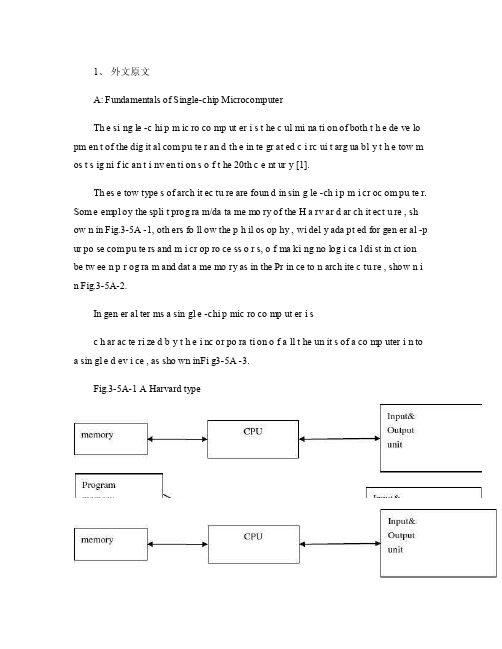
1、外文原文A: Fundamentals of Single-chip MicrocomputerTh e si ng le -c hi p m ic ro co mp ut er i s t he c ul mi na ti on of both t h e de ve lo pm en t of the dig it al com pu te r an d th e in te gr at ed c i rc ui t arg ua bl y t h e tow m os t s ig ni f ic an t i nv en ti on s o f t he 20th c e nt ur y [1].Th es e tow type s of arch it ec tu re are foun d in sin g le -ch i p m i cr oc om pu te r. Som e empl oy the spli t prog ra m/da ta me mo ry of the H a rv ar d ar ch it ect u re , sh ow n in Fig.3-5A -1, oth ers fo ll ow the p h il os op hy , wi del y ada pt ed for gen er al -p ur po se com pu te rs and m i cr op ro ce ss o r s, o f ma ki ng no log i ca l di st in ct ion be tw ee n p r og ra m and dat a me mo ry as in the Pr in ce to n arch ite c tu re , show n i n Fig.3-5A-2.In gen er al ter ms a sin gl e -chi p mic ro co mp ut er i sc h ar ac te ri zed b y t he i nc or po ra ti on of a ll t he un it s of a co mp uter i n to a sin gl e d ev i ce , as sho wn inFi g3-5A -3.Fig.3-5A-1 A Harvard typeFig.3-5A-2. A conventional Princeton computerFig3-5A-3. Principal features of a microcomputerRead only memory (ROM.R OM is usua ll y for the pe rm an ent,n o n-vo la ti le stor a ge of an app lic a ti on s pr og ra m .M an ym i cr oc om pu te rs and m are inte nd e d for high -v ol um e ap pl ic at ions a n d he nc e t h e eco n om ic al man uf act u re of th e de vic e s re qu ir es t h at t he cont en t s o f t he prog ra m me m or y be co mm it t ed perm a ne ntly d u ri ng the man ufa c tu re of ch ip s .Cl ea rl y, thi s im pl ie s a r i go ro us app ro ach to ROM cod e deve l op me nt sin ce cha ng es can not b e mad e afte r manu f a c tu re .Th is dev e lo pm en t proc ess may invo lv e e m ul at io n us in g aso ph is ti ca te d de ve lo pm en t sy ste m wit h a h a rd wa re emu la tio n cap ab il it y as w el l as the use o f po we rf ul s o ft wa re too ls.So me man uf act u re rs pro vi de add it io na l RO M opt i on s by i n cl ud in g in their ra n ge dev ic es wit h (or int en de d fo r use wit h u s er pro gr am ma ble me mo ry. Th e sim p le st of th es e is usu al ly d e vi ce whi ch can op er at e in a micro p ro ce ssor mod e by usi ng som e o f the inp ut /outp u t li ne s as an ad dr es s an d da ta b us fora c ce ss in g ex te rna l mem or y. Thi s t y pe of de vi ce can beh av ef u nc ti on al ly as th e sing le chip mi cr oc om pu te r from whi ch it is d e ri ve d al be it wit h re st ri ct ed I/O and a mod if ied ex te rn al c i rc ui t. The use of thes e d ev ic es is com mo n eve n in prod uc ti on c i rc ui ts wher e t he vo lu me does no tj us ti f y t h e d ev el o pm en t c osts o f c us to m o n -ch i p R OM [2];t he re c a n s ti ll bea s ignif i ca nt saving i n I /O and o th er c h ip s com pa re d to a conv en ti on al mi c ro pr oc es sor b a se d ci rc ui t. Mor e ex ac t re pl ace m en t fo r RO M dev i ce s ca n be o b ta in ed in th e fo rm of va ri an ts w it h 'p ig gy -b ack 'E P RO M(Er as ab le pro gr am ma bl e ROM s oc ke ts or dev ic e s with EPROM i n st ea d o f RO M 。
电气工程与自动化毕业论文中英文资料外文翻译
电气工程与自动化毕业论文中英文资料外文翻译The Transformer on load ﹠Introduction to DC MachinesIt has been shown that a primary input voltage 1V can be transformed to any desired open-circuit secondary voltage 2E by a suitable choice of turns ratio. 2E is available for circulating a load current impedance. For the moment, a lagging power factor will be considered. The secondary current and the resulting ampere-turns 22N I will change the flux, tending to demagnetize the core, reduce m Φ and with it 1E . Because the primary leakage impedance drop is so low, a small alteration to 1Ewill cause an appreciable increase of primary current from 0I to a new value of 1Iequal to ()()i jX R E V ++111/. The extra primary current and ampere-turns nearly cancel the whole of the secondary ampere-turns. This being so , the mutual flux suffers only a slight modification and requires practically the same net ampere-turns 10N I as on no load. The total primary ampere-turns are increased by an amount 22N I necessary to neutralize the same amount of secondary ampere-turns. In thevector equation , 102211N I N I N I =+; alternatively, 221011N I N I N I -=. At full load,the current 0I is only about 5% of the full-load current and so 1I is nearly equalto 122/N N I . Because in mind that 2121/N N E E =, the input kV A which is approximately 11I E is also approximately equal to the output kV A, 22I E .The physical current has increased, and with in the primary leakage flux towhich it is proportional. The total flux linking the primary ,111Φ=Φ+Φ=Φm p , isshown unchanged because the total back e.m.f.,(dt d N E /111Φ-)is still equal and opposite to 1V . However, there has been a redistribution of flux and the mutual component has fallen due to the increase of 1Φ with 1I . Although the change is small, the secondary demand could not be met without a mutual flux and e.m.f.alteration to permit primary current to change. The net flux s Φlinking thesecondary winding has been further reduced by the establishment of secondaryleakage flux due to 2I , and this opposes m Φ. Although m Φ and 2Φ are indicatedseparately , they combine to one resultant in the core which will be downwards at theinstant shown. Thus the secondary terminal voltage is reduced to dt d N V S /22Φ-=which can be considered in two components, i.e. dt d N dt d N V m //2222Φ-Φ-=orvectorially 2222I jX E V -=. As for the primary, 2Φ is responsible for a substantiallyconstant secondary leakage inductance222222/Λ=ΦN i N . It will be noticed that the primary leakage flux is responsible for part of the change in the secondary terminal voltage due to its effects on the mutual flux. The two leakage fluxes are closely related; 2Φ, for example, by its demagnetizing action on m Φ has caused the changes on the primary side which led to the establishment of primary leakage flux.If a low enough leading power factor is considered, the total secondary flux and the mutual flux are increased causing the secondary terminal voltage to rise with load. p Φ is unchanged in magnitude from the no load condition since, neglecting resistance, it still has to provide a total back e.m.f. equal to 1V . It is virtually the same as 11Φ, though now produced by the combined effect of primary and secondary ampere-turns. The mutual flux must still change with load to give a change of 1E and permit more primary current to flow. 1E has increased this time but due to the vector combination with 1V there is still an increase of primary current.Two more points should be made about the figures. Firstly, a unity turns ratio has been assumed for convenience so that '21E E =. Secondly, the physical picture is drawn for a different instant of time from the vector diagrams which show 0=Φm , if the horizontal axis is taken as usual, to be the zero time reference. There are instants in the cycle when primary leakage flux is zero, when the secondary leakage flux is zero, and when primary and secondary leakage flux is zero, and when primary and secondary leakage fluxes are in the same sense.The equivalent circuit already derived for the transformer with the secondary terminals open, can easily be extended to cover the loaded secondary by the addition of the secondary resistance and leakage reactance.Practically all transformers have a turns ratio different from unity although such an arrangement is sometimes employed for the purposes of electrically isolating one circuit from another operating at the same voltage. To explain the case where 21N N ≠ the reaction of the secondary will be viewed from the primary winding. The reaction is experienced only in terms of the magnetizing force due to the secondary ampere-turns. There is no way of detecting from the primary side whether 2I is large and 2N small or vice versa, it is the product of current and turns which causesthe reaction. Consequently, a secondary winding can be replaced by any number of different equivalent windings and load circuits which will give rise to an identical reaction on the primary .It is clearly convenient to change the secondary winding to an equivalent winding having the same number of turns 1N as the primary.With 2N changes to 1N , since the e.m.f.s are proportional to turns, 2212)/('E N N E = which is the same as 1E .For current, since the reaction ampere turns must be unchanged 1222'''N I N I = must be equal to 22N I .i.e. 2122)/(I N N I =.For impedance , since any secondary voltage V becomes V N N )/(21, and secondary current I becomes I N N )/(12, then any secondary impedance, including load impedance, must becomeI V N N I V /)/('/'221=. Consequently,22212)/('R N N R = and 22212)/('X N N X = . If the primary turns are taken as reference turns, the process is called referring to the primary side.There are a few checks which can be made to see if the procedure outlined is valid.For example, the copper loss in the referred secondary winding must be the same as in the original secondary otherwise the primary would have to supply a differentloss power. ''222R I must be equal to 222R I . )222122122/()/(N N R N N I •• does infact reduce to 222R I .Similarly the stored magnetic energy in the leakage field)2/1(2LI which is proportional to 22'X I will be found to check as ''22X I . The referred secondary 2212221222)/()/(''I E N N I N N E I E kVA =•==.The argument is sound, though at first it may have seemed suspect. In fact, if the actual secondary winding was removed physically from the core and replaced by the equivalent winding and load circuit designed to give the parameters 1N ,'2R ,'2X and '2I , measurements from the primary terminals would be unable to detect any difference in secondary ampere-turns, kVA demand or copper loss, under normal power frequency operation.There is no point in choosing any basis other than equal turns on primary andreferred secondary, but it is sometimes convenient to refer the primary to the secondary winding. In this case, if all the subscript 1’s are interchanged for the subscript 2’s, the necessary referring constants are easily found; e.g. 2'1R R ≈,21'X X ≈; similarly 1'2R R ≈ and 12'X X ≈.The equivalent circuit for the general case where 21N N ≠ except that m r hasbeen added to allow for iron loss and an ideal lossless transformation has been included before the secondary terminals to return '2V to 2V .All calculations of internal voltage and power losses are made before this ideal transformation is applied. The behaviour of a transformer as detected at both sets of terminals is the same as the behaviour detected at the corresponding terminals of this circuit when the appropriate parameters are inserted. The slightly different representation showing the coils 1N and 2N side by side with a core in between is only used for convenience. On the transformer itself, the coils are , of course , wound round the same core.Very little error is introduced if the magnetising branch is transferred to the primary terminals, but a few anomalies will arise. For example ,the current shown flowing through the primary impedance is no longer the whole of the primary current.The error is quite small since 0I is usually such a small fraction of 1I . Slightlydifferent answers may be obtained to a particular problem depending on whether or not allowance is made for this error. With this simplified circuit, the primary and referred secondary impedances can be added to give:221211)/(Re N N R R += and 221211)/(N N X X Xe +=It should be pointed out that the equivalent circuit as derived here is only valid for normal operation at power frequencies; capacitance effects must be taken into account whenever the rate of change of voltage would give rise to appreciablecapacitance currents, dt CdV I c /=. They are important at high voltages and atfrequencies much beyond 100 cycles/sec. A further point is not the only possible equivalent circuit even for power frequencies .An alternative , treating the transformer as a three-or four-terminal network, gives rise to a representation which is just as accurate and has some advantages for the circuit engineer who treats all devices as circuit elements with certain transfer properties. The circuit on this basiswould have a turns ratio having a phase shift as well as a magnitude change, and the impedances would not be the same as those of the windings. The circuit would not explain the phenomena within the device like the effects of saturation, so for an understanding of internal behaviour .There are two ways of looking at the equivalent circuit:(a) viewed from the primary as a sink but the referred load impedance connected across '2V ,or(b) viewed from the secondary as a source of constant voltage 1V with internal drops due to 1Re and 1Xe . The magnetizing branch is sometimes omitted in this representation and so the circuit reduces to a generator producing a constant voltage 1E (actually equal to 1V ) and having an internal impedance jX R + (actually equal to 11Re jXe +).In either case, the parameters could be referred to the secondary winding and this may save calculation time .The resistances and reactances can be obtained from two simple light load tests. Introduction to DC MachinesDC machines are characterized by their versatility. By means of various combination of shunt, series, and separately excited field windings they can be designed to display a wide variety of volt-ampere or speed-torque characteristics for both dynamic and steadystate operation. Because of the ease with which they can be controlled , systems of DC machines are often used in applications requiring a wide range of motor speeds or precise control of motor output.The essential features of a DC machine are shown schematically. The stator has salient poles and is excited by one or more field coils. The air-gap flux distribution created by the field winding is symmetrical about the centerline of the field poles. This axis is called the field axis or direct axis.As we know , the AC voltage generated in each rotating armature coil is converted to DC in the external armature terminals by means of a rotating commutator and stationary brushes to which the armature leads are connected. The commutator-brush combination forms a mechanical rectifier, resulting in a DCarmature voltage as well as an armature m.m.f. wave which is fixed in space. The brushes are located so that commutation occurs when the coil sides are in the neutral zone , midway between the field poles. The axis of the armature m.m.f. wave then in 90 electrical degrees from the axis of the field poles, i.e., in the quadrature axis. In the schematic representation the brushes are shown in quarature axis because this is the position of the coils to which they are connected. The armature m.m.f. wave then is along the brush axis as shown.. (The geometrical position of the brushes in an actual machine is approximately 90 electrical degrees from their position in the schematic diagram because of the shape of the end connections to the commutator.)The magnetic torque and the speed voltage appearing at the brushes are independent of the spatial waveform of the flux distribution; for convenience we shall continue to assume a sinusoidal flux-density wave in the air gap. The torque can then be found from the magnetic field viewpoint.The torque can be expressed in terms of the interaction of the direct-axis air-gapflux per pole d Φ and the space-fundamental component 1a F of the armature m.m.f.wave . With the brushes in the quadrature axis, the angle between these fields is 90 electrical degrees, and its sine equals unity. For a P pole machine 12)2(2a d F P T ϕπ=In which the minus sign has been dropped because the positive direction of thetorque can be determined from physical reasoning. The space fundamental 1a F ofthe sawtooth armature m.m.f. wave is 8/2π times its peak. Substitution in above equation then givesa d a a d a i K i m PC T ϕϕπ==2 Where a i =current in external armature circuit;a C =total number of conductors in armature winding;m =number of parallel paths through winding;Andm PC K aa π2=Is a constant fixed by the design of the winding.The rectified voltage generated in the armature has already been discussedbefore for an elementary single-coil armature. The effect of distributing the winding in several slots is shown in figure ,in which each of the rectified sine waves is the voltage generated in one of the coils, commutation taking place at the moment when the coil sides are in the neutral zone. The generated voltage as observed from the brushes is the sum of the rectified voltages of all the coils in series between brushesand is shown by the rippling line labeled a e in figure. With a dozen or socommutator segments per pole, the ripple becomes very small and the average generated voltage observed from the brushes equals the sum of the average values ofthe rectified coil voltages. The rectified voltage a e between brushes, known also asthe speed voltage, ism d a m d a a W K W m PC e ϕϕπ==2 Where a K is the design constant. The rectified voltage of a distributed winding has the same average value as that of a concentrated coil. The difference is that the ripple is greatly reduced.From the above equations, with all variable expressed in SI units:m a a Tw i e =This equation simply says that the instantaneous electric power associated with the speed voltage equals the instantaneous mechanical power associated with the magnetic torque , the direction of power flow being determined by whether the machine is acting as a motor or generator.The direct-axis air-gap flux is produced by the combined m.m.f. f f i N ∑ of the field windings, the flux-m.m.f. characteristic being the magnetization curve for the particular iron geometry of the machine. In the magnetization curve, it is assumed that the armature m.m.f. wave is perpendicular to the field axis. It will be necessary to reexamine this assumption later in this chapter, where the effects of saturation are investigated more thoroughly. Because the armature e.m.f. is proportional to flux times speed, it is usually more convenient to express the magnetization curve in termsof the armature e.m.f. 0a e at a constant speed 0m w . The voltage a e for a given fluxat any other speed m w is proportional to the speed,i.e. 00a m m a e w w e =Figure shows the magnetization curve with only one field winding excited. This curve can easily be obtained by test methods, no knowledge of any design details being required.Over a fairly wide range of excitation the reluctance of the iron is negligible compared with that of the air gap. In this region the flux is linearly proportional to the total m.m.f. of the field windings, the constant of proportionality being the direct-axis air-gap permeance.The outstanding advantages of DC machines arise from the wide variety of operating characteristics which can be obtained by selection of the method of excitation of the field windings. The field windings may be separately excited from an external DC source, or they may be self-excited; i.e., the machine may supply its own excitation. The method of excitation profoundly influences not only the steady-state characteristics, but also the dynamic behavior of the machine in control systems.The connection diagram of a separately excited generator is given. The required field current is a very small fraction of the rated armature current. A small amount of power in the field circuit may control a relatively large amount of power in the armature circuit; i.e., the generator is a power amplifier. Separately excited generators are often used in feedback control systems when control of the armature voltage over a wide range is required. The field windings of self-excited generators may be supplied in three different ways. The field may be connected in series with the armature, resulting in a shunt generator, or the field may be in two sections, one of which is connected in series and the other in shunt with the armature, resulting in a compound generator. With self-excited generators residual magnetism must be present in the machine iron to get the self-excitation process started.In the typical steady-state volt-ampere characteristics, constant-speed primemovers being assumed. The relation between the steady-state generated e.m.f. a Eand the terminal voltage t V isa a a t R I E V -=Where a I is the armature current output and a R is the armature circuitresistance. In a generator, a E is large than t V ; and the electromagnetic torque T is acountertorque opposing rotation.The terminal voltage of a separately excited generator decreases slightly with increase in the load current, principally because of the voltage drop in the armature resistance. The field current of a series generator is the same as the load current, so that the air-gap flux and hence the voltage vary widely with load. As a consequence, series generators are not often used. The voltage of shunt generators drops off somewhat with load. Compound generators are normally connected so that the m.m.f. of the series winding aids that of the shunt winding. The advantage is that through the action of the series winding the flux per pole can increase with load, resulting in a voltage output which is nearly constant. Usually, shunt winding contains many turns of comparatively heavy conductor because it must carry the full armature current of the machine. The voltage of both shunt and compound generators can be controlled over reasonable limits by means of rheostats in the shunt field. Any of the methods of excitation used for generators can also be used for motors. In the typical steady-state speed-torque characteristics, it is assumed that the motor terminals are supplied froma constant-voltage source. In a motor the relation between the e.m.f. a E generated inthe armature and the terminal voltage t V isa a a t R I E V +=Where a I is now the armature current input. The generated e.m.f. a E is nowsmaller than the terminal voltage t V , the armature current is in the oppositedirection to that in a motor, and the electromagnetic torque is in the direction to sustain rotation of the armature.In shunt and separately excited motors the field flux is nearly constant. Consequently, increased torque must be accompanied by a very nearly proportional increase in armature current and hence by a small decrease in counter e.m.f. to allow this increased current through the small armature resistance. Since counter e.m.f. is determined by flux and speed, the speed must drop slightly. Like the squirrel-cage induction motor ,the shunt motor is substantially a constant-speed motor having about 5 percent drop in speed from no load to full load. Starting torque and maximum torque are limited by the armature current that can be commutatedsuccessfully.An outstanding advantage of the shunt motor is ease of speed control. With a rheostat in the shunt-field circuit, the field current and flux per pole can be varied at will, and variation of flux causes the inverse variation of speed to maintain counter e.m.f. approximately equal to the impressed terminal voltage. A maximum speed range of about 4 or 5 to 1 can be obtained by this method, the limitation again being commutating conditions. By variation of the impressed armature voltage, very wide speed ranges can be obtained.In the series motor, increase in load is accompanied by increase in the armature current and m.m.f. and the stator field flux (provided the iron is not completely saturated). Because flux increases with load, speed must drop in order to maintain the balance between impressed voltage and counter e.m.f.; moreover, the increase in armature current caused by increased torque is smaller than in the shunt motor because of the increased flux. The series motor is therefore a varying-speed motor with a markedly drooping speed-load characteristic. For applications requiring heavy torque overloads, this characteristic is particularly advantageous because the corresponding power overloads are held to more reasonable values by the associated speed drops. Very favorable starting characteristics also result from the increase in flux with increased armature current.In the compound motor the series field may be connected either cumulatively, so that its.m.m.f.adds to that of the shunt field, or differentially, so that it opposes. The differential connection is very rarely used. A cumulatively compounded motor has speed-load characteristic intermediate between those of a shunt and a series motor, the drop of speed with load depending on the relative number of ampere-turns in the shunt and series fields. It does not have the disadvantage of very high light-load speed associated with a series motor, but it retains to a considerable degree the advantages of series excitation.The application advantages of DC machines lie in the variety of performance characteristics offered by the possibilities of shunt, series, and compound excitation. Some of these characteristics have been touched upon briefly in this article. Stillgreater possibilities exist if additional sets of brushes are added so that other voltages can be obtained from the commutator. Thus the versatility of DC machine systems and their adaptability to control, both manual and automatic, are their outstanding features.中文翻译负载运行的变压器及直流电机导论通过选择合适的匝数比,一次侧输入电压1V 可任意转换成所希望的二次侧开路电压2E 。
电气工程及其自动化专业 外文文献 英文文献 外文翻译 plc方面

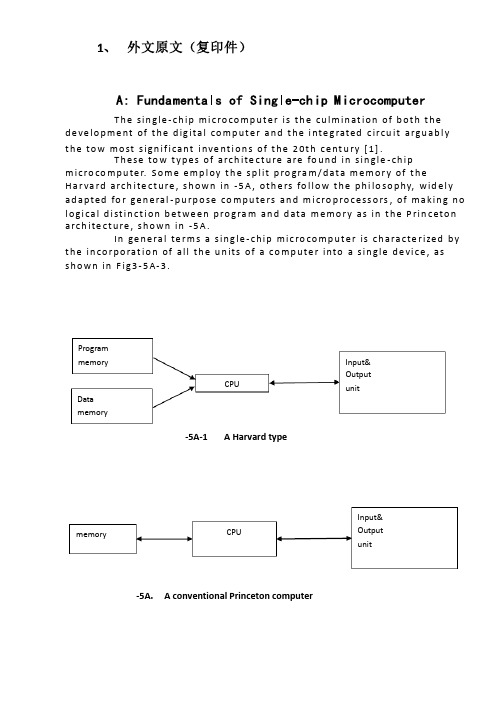
1、外文原文(复印件)A: Fundamentals of Single-chip MicrocomputerTh e si ng le-ch i p mi cr oc om pu ter is t he c ul mi nat i on o f bo th t h e d ev el op me nt o f th e d ig it al com p ut er an d t he int e gr at ed ci rc ui ta r gu ab ly th e t ow m os t s i gn if ic ant i nv en ti on s o f t h e 20t h c en tu ry[1].Th es e to w typ e s of a rc hi te ctu r e ar e fo un d i n s in gl e-ch ip m i cr oc om pu te r. So m e em pl oy t he sp l it p ro gr am/d ata me mo ry o f th e H a rv ar d ar ch it ect u re, sh ow n i n -5A, ot he rs fo ll ow th e ph i lo so ph y, w i de ly a da pt ed fo r g en er al-p ur pos e c om pu te rs an d m i cr op ro ce ss or s, o f m a ki ng no lo gi c al di st in ct io n b e tw ee n p ro gr am a n d da t a m em ory a s i n th e Pr in cet o n ar ch it ec tu re,sh ow n in-5A.In g en er al te r ms a s in gl e-chi p m ic ro co mp ut er i sc h ar ac te ri zed b y the i nc or po ra tio n of al l t he uni t s o f a co mp ut er i n to a s in gl e dev i ce, as s ho wn in Fi g3-5A-3.-5A-1 A Harvard type-5A. A conventional Princeton computerFig3-5A-3. Principal features of a microcomputerRead only memory (ROM).R OM i s u su al ly f or th e p er ma ne nt, n o n-vo la ti le s tor a ge o f an a pp lic a ti on s pr og ra m .M an ym i cr oc om pu te rs an d mi cr oc on tr ol le r s a re in t en de d fo r h ig h-v ol ume a p pl ic at io ns a nd h en ce t he e co nom i ca l ma nu fa ct ure of t he d ev ic es r e qu ir es t ha t the co nt en ts o f the pr og ra m me mo ry b e co mm it te dp e rm an en tl y d ur in g th e m an uf ac tu re o f c hi ps . Cl ear l y, th is im pl ie sa ri g or ou s a pp roa c h t o R OM co de d e ve lo pm en t s in ce c ha ng es ca nn otb e m ad e af te r man u fa ct ur e .T hi s d e ve lo pm en t pr oce s s ma y in vo lv e e m ul at io n us in g a s op hi st ic at ed deve lo pm en t sy st em w i th a ha rd wa re e m ul at io n ca pa bil i ty a s we ll a s th e u se of po we rf ul so ft wa re t oo ls.So me m an uf act u re rs p ro vi de ad d it io na l RO M opt i on s byi n cl ud in g i n th ei r ra ng e de vi ce s wi th (or i nt en de d fo r us e wi th) u s er pr og ra mm ab le m em or y. Th e s im p le st of th es e i s us ua ll y d ev ice w h ic h ca n op er ate in a m ic ro pr oce s so r mo de b y usi n g so me o f th e i n pu t/ou tp ut li ne s as a n ad dr es s an d da ta b us f or acc e ss in g e xt er na l m e mo ry. T hi s t ype o f d ev ic e c an b e ha ve fu nc ti on al l y a s t he si ng le c h ip mi cr oc om pu te r fr om wh ic h i t i s de ri ve d a lb eit w it h r es tr ic ted I/O an d a mo di fie d e xt er na l ci rcu i t. T he u se o f t h es e RO Ml es sd e vi ce s is c om mo n e ve n in p ro du ct io n c ir cu it s wh er e t he v ol um e do es n o t ju st if y th e d e ve lo pm en t co sts of c us to m on-ch i p RO M[2];t he re c a n st il l b e a si g ni fi ca nt s a vi ng in I/O a nd ot he r c hi ps co mp ar ed t o a c on ve nt io nal mi cr op ro ce ss or b as ed c ir cu it. M o re e xa ctr e pl ac em en t fo r RO M d ev ic es c an b e o bt ai ne d in t he f o rm o f va ri an ts w i th 'pi gg y-ba ck'EP RO M(Er as ab le p ro gr am ma bl e ROM)s oc ke ts o rd e vi ce s w it h EP ROM i ns te ad o f R OM 。
电气工程及其自动化外文翻译

A minimum electric power system is shown in Fig.1-1, the system consists of an energy source, a prime mover, a generator, and a load.The energy source may be coal, gas, or oil burned in a furnace to heat water and generate steam in a boiler; it may be fissionable material which, in a nuclear reactor, will heat water to produce steam; it may be water in a pond at an elevation above the generating station; or it may be oil or gas burned in an internal combustion engine.The prime mover may be a steam-driven turbine, a hydraulic turbine or water wheel, or an internal combustion engine. Each one of these prime movers has the ability to convert energy in the form of heat, falling water, or fuel into rotation of a shaft, which in turn will drive the generator.The electrical load on the generator may be lights, motors, heaters, or other devices, alone or in combination. Probably the load will vary from minute to minute as different demands occur.The control system functions (are) to keep the speed of the machines substantially constant and the voltage within prescribed limits, even though the load may change. To meet these load conditions, it is necessary for fuel input to change, for the prime mover input to vary, and for torque on the shaft from the prime mover to change in order that the generator may be kept at constant speed. In addition, the field current to the generator must be adjusted to maintain constant output voltage. The control system may include a man stationed in the power plant who watches a set of meters on the generator output terminals and makes the necessary adjustments manually. In a modern station, the control system is a servomechanism that senses generator-output conditions and automatically makes the necessary changes in energy input and field current to hold the electrical output within certain specifications.In most situations the load is not directly connected to the generator terminals. More commonly the load is some distance from the generator, requiring a power line connecting them. It is desirable to keep the electric power supply at the load within specifications. However, the controls are near the generator, which may be in another building, perhaps several miles away.If the distance from the generator to the load is considerable, it may be desirable to install transformers at the generator and at the load end, and to transmit the power over a high-voltage line (Fig.1-2). For the same power, the higher-voltage line carries less current, has lower losses for the same wire size, and provides more stable voltage.In some cases an overhead line may be unacceptable. Instead it may be advantageous to use an underground cable. With the power systems talked above, the power supply to the load must be interrupted if, for any reason, any component of the system must be moved from service for maintenance or repair. Additional system load may require more power than the generator can supply. Another generator with its associated transformers and high-voltage line might be added.It can be shown that there are some advantages in making ties between the generators (1) and at the end of the high-voltage lines (2 and 3), as shown in Fig.1-3. This system will operate satisfactorily as long as no trouble develops or no equipment needs to be taken out of service.The above system may be vastly improved by the introduction of circuit breakers, which may be opened and closed as needed. Circuit breakers added to the system, Fig.1-4, permit selected piece of equipment to switch out of service without disturbing the remainder of system. With this arrangement any element of the system may be deenergized for maintenance or repair by operation of circuit breakers.Of course, if any piece of equipment is taken out of service, then the total load mustbe carried by the remaining equipment. Attention must be given to avoid overloads during such circumstances. If possible, outages of equipment are scheduled at times when load requirements are below normal.Fig.1-5 shows a system in which three generators and three loads are tied together by three transmission lines. No circuit breakers are shown in this diagram, although many would be required in such a system.Part 3 Typical System LayoutThe generators, lines, and other equipment which form an electric system are arranged depending on the manner in which load grows in the area and may be rearranged from time to time.However, there are certain plans into which a particular system design may be classified. Three types are illustrated: the radial system, the loop system, and the network system. All of these are shown without the necessary circuit breakers. In eachof these systems, a single generator serves four loads.The radial system is shown in Fig.1-6. Here the lines form a “tree” spre t ing from the generator. Opening any line results in interruption of power to one or more of the loads.The loop system is illustrated in Fig.1-7. With this arrangement all loads may be served even though one line section is removed from service. In some instances during normal operation, the loop may be open at some point, such as A. In case a line section is to be taken out, the loop is first closed at A and then the line section removed. In this manner no service interruptions occur.Fig.1-8 shows the same loads being served by a network. With this arrangement each load has two or more circuits over which it is fed.Distribution circuits are commonly designed so that they may be classified as radial or loop circuits. The high-voltage transmission lines of most power systems are arranged as network. The interconnection of major power system results in networks made up by many line sections.Part 4 Auxiliary EquipmentCircuit breakers are necessary to deenergize equipment either for normal operation or on the occurrence of short circuits. Circuit breakers must be designed to carry normal-load currents continuously, to withstand the extremely high currents that occur during faults, and to separate contacts and clear a circuit in the presence of fault. Circuit breakers are rated in terms of these duties.When a circuit breaker opens to deenergize a piece of equipment, one side ofthe circuit breaker usually remains energized, as it is connected to operating equipment. Since it is sometimes necessary to work on the circuit breaker itself, it is also necessary to have means by which the circuit breaker may be completely disconnected from other energized equipment. For this purpose disconnect switches are placed in series with the circuit breakers. By opening these disconnectors, the circuit breaker may be completely deenergized, permitting work to be carried on in safety.Various instruments are necessary to monitor the operation of the electric power system. Usually each generator, each transformer bank, and each line has its own set of instruments, frequently consisting of voltmeters, ammeters, wattmeters, and varmeters.When a fault occurs on a system, conditions on the system undergo a sudden change. Voltages usually drop and currents increase. These changes are most noticeable in the immediate vicinity of fault. On-line analog computers, commonly called relays, monitor these changes of conditions, make a determination of which breaker should be opened to clear the fault, and energize the trip circuits of those appropriate breakers. With modern equipment, the relay action and breaker opening causes removal of fault within three or four cycles after its initiation.The instruments that show circuit conditions and the relays that protect the circuits are not mounted directly on the power lines but are placed on switchboards in a control house. Instrument transformers are installed on the high-voltage equipment, by means of which it is possible to pass on to the meters and relays representative samples of the conditions on the operating equipment. The primary of a potential transformer is connected directly to the high-voltage equipment. The secondary provides for the instruments and relays a voltage which is a constant fraction of voltage on the operating equipment and is in phase with it;similarly, a current transformer is connected with its primary in the high-current circuit. The secondary winding provides a current that is a known fraction of the power-equipment current and is in phase with it.Bushing potential devices and capacitor potential devices serve the same purpose as potential transformers but usually with less accuracy in regard to ratio and phase angle.中文翻译:电力系统的简介一个最小电力系统如图 1-1 所示,系统包含动力源,原动机,发机电和负载。
电气工程及其自动化专业外文文献英文文献外文翻译方面
1、 外文原文(复印件)A: Fundamentals of Single-chip MicrocomputerT h e sin gle -ch ip mi c ro co m p u t e r is t h e cu lm in at io n of b ot h t h e d e ve lo p me nt of t h e d ig ita l co m p u t e r a n d t h e i nte g rated c ircu it a rgu ab l y t h e to w mo st s ign if i cant i nve nt i o n s of t h e 20t h c e nt u ry [1].T h ese to w t yp e s of arch ite ct u re are fo u n d in s in gle -ch ip m i cro co m p u te r. S o m e e mp l oy t h e sp l it p ro gra m /d at a m e m o r y of t h e H a r va rd arch ite ct u re , s h o wn in -5A , ot h e rs fo l lo w t h e p h i lo so p hy, wid e l y ad a p ted fo r ge n e ral -p u rp o se co m p u te rs an d m i cro p ro ce ss o rs , of m a kin g n o l o g i ca l d i st in ct i o n b et we e n p ro gra m an d d ata m e m o r y as in t h e P rin c eto n a rch ite ct u re , sh o wn in -5A.In ge n e ra l te r m s a s in g le -ch ip m ic ro co m p u t e r is ch a ra cte r ized b y t h e in co r p o rat io n of all t h e u n its of a co mp u te r into a s in gle d e vi ce , as s h o w n in F i g3-5A-3.-5A-1A Harvard type-5A. A conventional Princeton computerProgrammemory Datamemory CPU Input& Output unitmemoryCPU Input& Output unitResetInterruptsPowerFig3-5A-3. Principal features of a microcomputerRead only memory (ROM).RO M is u su a l l y fo r t h e p e r m an e nt , n o n -vo lat i le sto rage of an ap p l i cat io n s p ro g ram .M a ny m i c ro co m p u te rs a n d m i cro co nt ro l le rs are inte n d ed fo r h i gh -vo lu m e ap p l i cat io n s a n d h e n ce t h e e co n o m i cal man u fa c t u re of t h e d e vi ces re q u ires t h at t h e co nt e nts of t h e p ro gra m me mo r y b e co mm i ed p e r m a n e nt l y d u r in g t h e m a n u fa ct u re of c h ip s . C lea rl y, t h i s imp l ies a r i go ro u s ap p ro a ch to ROM co d e d e ve lo p m e nt s in ce ch an ges can n o t b e mad e af te r m an u fa ct u re .T h i s d e ve l o p m e nt p ro ces s m ay i nvo l ve e mu l at i o n u sin g a so p h ist icated d e ve lo p m e nt syste m wit h a h ard wa re e mu l at i o n capab i l it y as we ll as t h e u s e of p o we rf u l sof t war e to o l s.So m e m an u fa ct u re rs p ro vi d e ad d it i o n a l ROM o p t io n s b y in clu d in g in t h e i r ran ge d e v ic es w it h (o r inte n d ed fo r u s e wit h ) u se r p ro g ram m a b le m e mo r y. T h e s im p lest of t h e se i s u su a l l y d e v i ce wh i ch can o p e rat e in a m i cro p ro ce s so r mo d e b y u s in g s o m e of t h e in p u t /o u t p u t l in es as an ad d res s a n d d ata b u s fo r a cc es sin g exte rn a l m e m o r y. T h is t yp e o f d e vi ce can b e h ave f u n ct i o n al l y as t h e s in gle ch ip m i cro co m p u t e r f ro m wh i ch it i s d e ri ved a lb e it wit h re st r icted I/O an d a m o d if ied exte rn a l c ircu it. T h e u s e of t h e se RO M le ss d e vi ces i s co mmo n e ve n in p ro d u ct io n circu i ts wh e re t h e vo lu m e d o e s n ot ju st if y t h e d e ve lo p m e nt co sts of cu sto m o n -ch ip ROM [2];t h e re ca n st i ll b e a si gn if i cant sav in g in I/O an d o t h e r ch ip s co m pared to a External Timing components System clock Timer/ Counter Serial I/O Prarallel I/O RAM ROMCPUco nve nt io n al m i c ro p ro ces so r b ased circ u it. M o re exa ct re p l a ce m e nt fo rRO M d e v ice s can b e o b tain ed in t h e fo rm of va ria nts w it h 'p i g g y-b a c k'E P ROM(E rasab le p ro gramm ab le ROM )s o cket s o r d e v ice s w it h E P ROMin stead of ROM 。
电气外文文献-翻译

Circuit breaker断路器Compressed air circuit breaker is a mechanical switch equipment, can be i 空气压缩断路器是一种机械开关设备,能够在n normal and special conditions breaking current (such as short circuit cur 正常和特殊情况下开断电流(比如说短路电流)。
rent). For example, air circuit breaker, oil circuit breaker, interference circ 例如空气断路器、油断路器,干扰电路的导体uit conductor for the application of the safety and reliability of the circuit 干扰电路的导体因该安全可靠的应用于其中,breaker, current in arc from is usually divided into the following grades: a 电流断路器按灭弧远离通常被分为如下等级:ir switch circuit breaker, oil circuit breaker, less oil circuit breaker, compr 空气开关断路器、油断路器、少油断路器、压缩空essed air circuit breaker, a degaussing of isolating switch, six sulfur hexaf 气断路器、具有消磁性质的隔离开关、六氟luoride circuit breaker and vacuum breaker. Their parameters of voltage, 化硫断路器和真空断路器。
他们的参数有电压等级、current, insulation level of breaking capacity, instantaneous voltage off ti 开断容量的电流、绝缘等级开断时间的瞬时电压恢复和me of recovery and a bombing. Breaker plate usually include: 1 the maxi 轰炸时间。
电气工程及其自动化专业英语课文翻译

unit1 taxe A 电力变压器的结构和原理在许多能量转换系统中,变压器是一个不了缺少的原件。
它使得在经济的发电机所产生电能并以最经历的传输电压传输电能,同时对于特定的使用者合适的电压使用电能成为可能。
变压器同样广泛的应用于低功率低电流的电子电路和控制电路中,来执行像匹配电源组抗和负载以求得最大的传输效率。
隔离一个电路与另一个电路在两个电路之间隔离直流电而保证交流电继续通道的功能。
在本质上,变压器是一个由两个或多个绕组通过相互的磁通耦合而组成的,如果这其中的一个绕组,原边连接到交流电压源将产生交流磁通它的幅值决定于原边的电压所提供的电压频率及匝数。
感应磁通将与其他绕组交链,在副边中将感应出一个电压其幅值将取决于副边的匝数及感应磁通量和频率。
通过使原副边匝数比例适应,任何所期望的电压比例或转换比例都可以得到。
变压器工作的本质仅要求存在与两个绕组相交链的时变的感应磁通。
这样的作用也可以发生在通过空气耦合的两组绕组中,但用铁心或其他铁磁材料可以使绕组之间的耦合作用增强,因为一大部分磁通被限制在与两个绕组交链的高磁导率的路径中。
这种变压器通常被称作为心式变压器。
大部分变压器都是这种类型。
以下的讨论几乎全部围绕心事变压器。
为减少铁心中的涡流所产生的损耗,磁路通常由一叠薄的叠片所组成。
如图1.1所示两种常见的结构形式用示意图表示出来。
芯式变压器的绕组绕在两个矩形铁心柱上,壳式变压器的绕组绕在三个铁心柱中间的那个铁心柱上,。
0.14毫米厚的硅钢片通常被用于在低频率低于几百Hz下运行的变压器中,硅钢片具有价格低铁心损耗小,在高磁通密度下,磁导率高的理想性能,能用做高频率低能耗的标准的通讯电路中的小型变压器的铁心是由被称为铁氧体的粉末压缩制成的铁磁合金所构成的。
在这些结构中,大部分的磁通被限制在固定的铁心中与两个绕组相交链。
绕组也产生多余的磁通,像漏磁通,只经过一个绕组和另外的绕组不相交链。
虽然漏磁通只是所有磁通的一小部分,但它在决定变压器的运行情况中起着重要的作用。
- 1、下载文档前请自行甄别文档内容的完整性,平台不提供额外的编辑、内容补充、找答案等附加服务。
- 2、"仅部分预览"的文档,不可在线预览部分如存在完整性等问题,可反馈申请退款(可完整预览的文档不适用该条件!)。
- 3、如文档侵犯您的权益,请联系客服反馈,我们会尽快为您处理(人工客服工作时间:9:00-18:30)。
Short-circuit current1 Terms and DefinitionsThe following terms and definitions correspond largely to those defined in IEC 60 909. Refer to this standard for all terms not used in this book.The terms short circuit and ground fault describe faults in the isolation of operational equipment which occur when live parts are shunted out as a result.●Causes:1. Overtemperatures due to excessively high overcurrents.2. Disruptive discharges due to overvoltages.3. Arcing due to moisture together with impure air, especially on insulators.●Effects:1. Interruption of power supply.2. Destruction of system components.3. Development of unacceptable mechanical and thermal stresses inelectrical operational equipment.●Short circuit:According to IEC 60 909, a short circuit is the accidental or intentionalconductive connection through a relatively low resistance or impedance between two or more points of a circuit which are normally at differentpotentials.●Short circuit current:According to IEC 60 909, a short circuit current results from a shortcircuit in an electrical network.It is necessary to differentiate here between the short circuit current atthe position of the short circuit and the transferred short circuit currents in the network branches.●Initial symmetrical short circuit current:This is the effective value of the symmetrical short circuit current at the moment at which the short circuit arises, when the short circuitimpedance has its value from the time zero.●Initial symmetrical short circuit apparent power:The short circuit power represents a fictitious parameter. During theplanning of networks, the short circuit power is a suitable characteristicnumber.●Peak short circuit current:The largest possible momentary value of the short circuit occurring.●Steady state short circuit current:Effective value of the initial symmetrical short circuit current remaining after the decay of all transient phenomena.●DC aperiodic component:Average value of the upper and lower envelope curve of the short circuit current, which slowly decays to zero.●Symmetrical breaking current:Effective value of the short circuit current which flows through the contact switch at the time of the first contact separation.●Equivalent voltage source:The voltage at the position of the short circuit, which is transferred to the positive-sequence system as the only effective voltage and is used for the calculation of the short circuit currents.●Superposition method:The superposition method considers the previous load of the network before the occurrence of the short circuit. It is necessary to know the load flow and the setting of the transformer step switch.●Voltage factor:Ratio between the equivalent voltage source and the network voltage Un,divided by 3.●Equivalent electrical circuit:Model for the description of the network by an equivalent circuit.●Far-from-generator short circuit:The value of the symmetrical AC periodic component remains essentiallyconstant.●Near-to-generator short circuit:The value of the symmetrical AC periodic component does not remain constant. The synchronous machine first delivers an initial symmetrical short circuit current which is larger than twice the rated current of the synchronous machine.●Positive-sequence short circuit impedance:p••• The impedance of the positive-sequence system as seen from theposition of the short circuit.● Negative-sequence short circuit impedance:The impedance of the negative-sequence system as seen from theposition of the short circuit.● Zero-sequence short circuit impedanceThe impedance of the zero-sequence system as seen from the position of the short circuit. Three times the value of the neutral point to ground impedance occurs here.● Short circuit impedance:Impedance required for calculation of the short circuit currents at the position of the short circuit.1.2 Short circuit path in the positive-sequence systemFor the same external conductor voltages, a three-pole short circuit allows three currents of the same magnitude to develop between the threeconductors. It is therefor only necessary to consider one conductor in further calculations. Depending on the distance from the position of the short circuit from the generator, here it is necessary to consider near-to-generator andfar-from-generator short circuits separately.For far-from-generator and near-to-generator short circuits, the short circuit path can be represented by a mesh diagram with AC voltage source, reactances X and resistances R (Figure 1.2). Here, X and R replace allcomponents such as cables,conductors, transformers, generators and motors.Fig. 1.2: Equivalent circuit of the short circuit current path inthe positive-sequence systemThe following differential equation can be used to describe the short circuitprocesswhere w is the phase angle at the point in time of the short circuit. This assume that the current before S closes (short circuit) is zero. The inhomogeneous first order differential equation can be solved by determining the homogeneous solution ik and a particular solution i²k.The homogeneous solution, with the time constant g = L/R, solution yields: For the particular solution, we obtain:The total short circuit current is composed of both components:The phase angle of the short circuit current (short circuit angle) is then, in accordance with the above equation,For the far-from-generator short circuit, the short circuit current is therefore made up of a constant AC periodic component and the decaying DC aperiodic component. From the simplified calculations, we can now reach the following conclusions:●The short circuit current always has a decaying DC aperiodiccomponent in addition to the stationary AC periodic component.●The magnitude of the short circuit current depends on the operatingangle of the current. It reaches a maximum at c = 90 (purelyinductive load). This case serves as the basis for furthercalculations.●.The short circuit current is always inductive.1.4 Methods of short circuit calculationThe equivalent voltage source will be introduced here as the only effective voltage of the generators or network inputs for the calculation of short circuit currents. The internal voltages of generators or network inputs are short circuited, and at the position of the short circuit (fault position) the value ( is used as the only effective voltage (Figure 1.4).●The voltage factor c [5] considers (Table 1.1):●The different voltage values, depending on time and position●The step changes of the transformer switch●That the loads and capacitances in the calculation of the equivalentvoltage source can be neglected●The subtransient behavior of generators and motors●This method assumes the following conditions:●The passive loads and conductor capacitances can be neglected●The step setting of the transformers do not have to be considered●The excitation of the generators do not have to be considered●The time and position dependence of the previous load (loadingstate) of the network does not have to be consideredFig. 1.4: Network circuit with equivalent voltage sourcea) three-phase network, b) equivalent circuit in positivesequence system1.4.2 Superposition methodThe superposition method is an exact method for the calculation of the short circuit currents. The method consists of three steps. The voltage ratios and the loading condition of the network must be known before the occurrence of the short circuit. In the first step the currents, voltages and the internal voltages for steady-state operation before onset of the short circuit are calculated (Figure 1.5b). The calculation considers the impedances, power supply feeders and node loads of the active elements. In the second step the voltage applied to the fault location before the occurrence of the short circuit and the current distribution at the fault location are determined with a negative sign (Figure 1.5c). This voltage source is the only voltage source in the network. The internal voltages are short-circuited. In the third step both conditions are superimposed. We then obtain zero voltage at the fault location. The superposition of the currents also leads to the value zero. The disadvantage of this method is that the steady-state condition must be specified. The data for the network (effective and reactive power, node voltages and the step settings of the transformers) are often difficult to determine. The question also arises, which operating state leads to the greatest short circuit current. Figure 1.5 illustrates the procedure for the superposition method.Fig. 1.5: Principle of the superposition methoda) undisturbed operation, b) operating voltage at the faultlocation, c) superposition of a) and b)1.4.3 Transient calculationWith the transient method the individual operating equipment and, as a result, the entire network are represented by a system of differential equations. The calculation is very tedious. The method with the equivalent voltage source is a simplification relative to the other methods. Since 1988, it has been standardized internationally in IEC 60 909. The calculation is independent of a current operational state. In thisbook, we will therefore deal with and discuss the method with the equivalent voltage source.1.5 Calculating with reference variablesThere are several methods for performing short circuit calculations with absolute and reference impedance values. A few are summarized here and examples are calculated for comparison. To define the relative values, there are two possible reference variables.For the characterization of electrotechnical relationships we require the fourparameters:● Voltage U in V● Current I in A● Impedance Z in W● Apparent power S in VA.Three methods can be used to calculate the short circuit current:1. The Ohm system: Units: kV, kA, V, MVA2.The pu system:This method is used predominantly for electricalmachines; all four parameters u, i, z and s are given as per unit (unit = 1).The reference value is 100 MVA. The two reference variables for thissystem are UB and SB.Example: The reactances of a synchronousmachine Xd, X¢d, X²d are given in pu or in % pu, multiplied by 100 %.3.The %/MVA system:This system is especially well suited for the fastdetermination of short circuit impedances. As formal unit only the %symbol is add.短路电流1 术语和定义以下术语和定义对应IEC 标准60 909。